Language selection

Search

Patent 2313898 Summary

Third-party information liability

Some of the information on this Web page has been provided by external sources. The Government of Canada is not responsible for the accuracy, reliability or currency of the information supplied by external sources. Users wishing to rely upon this information should consult directly with the source of the information. Content provided by external sources is not subject to official languages, privacy and accessibility requirements.

Claims and Abstract availability

Any discrepancies in the text and image of the Claims and Abstract are due to differing posting times. Text of the Claims and Abstract are posted:

  • At the time the application is open to public inspection;
  • At the time of issue of the patent (grant).
(12) Patent Application: (11) CA 2313898
(54) English Title: DOVE TAIL ANGLE DEGREE FINDER
(54) French Title: DETECTEUR DE DEGRE D'ANGLE DE QUEUE D'ARONDE
Status: Dead
Bibliographic Data
Abstracts

English Abstract


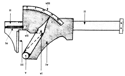
This invention, called a Dove Tail Angle Degree Finder, is a mechanical
measuring device. It is a router application accessory enabling the operator
to find the specific degree of the cutting angle of dovetail router bits.
Distinct dovetail applications require specific degrees. The degree of
the cutting angle is usual not marked on the router bit's shaft. A custom
ground or resharpened bit also has a specific cutting angle.
This invention is very handy in a shop with an inventory of many
different dovetail bits.
Bits can be specified in a frustration less, fast and accurate way.


Claims

Note: Claims are shown in the official language in which they were submitted.


THE EMBODIMENTS OF THE INVENTION IN WHICH AN EXCLUSIVE
PROPERTY OR PRIVILEGE IS CLAIMED ARE DEFINED AS FOLLOWS:

1: A Device enabling one to find and measure the degree of
dovetail router bits and other non parallel objects.
2: A stationary jaw affixed to .alpha.. sliding bar
3: The stationary jaw as defined in claim 2 is to be furnished with a
plate at it's inner side whereby creating a large surface area for the router
bit to rest against.
4: A specially shaped movable jaw which is riding on the sliding bar
as defined in claim 2.
5: A hole through the bottom-tip is to be furnished to the specially
shaped movable jaw as defined in claim 4 to hold the pin and coil spring for
the clocklike hand.
6: A clocklike hand is to be installed v1a a coil spring to said hole as
defined in claim 5.
7: A stopper has to be furnished on the movable jaw in order for the
spring loaded clock like hand to rest in it's zero degree reading position.
8: A scale with increments of dovetail-bit degree measurements is
to be incorporated and located at the prober distance for the tip of the
clocklike hand as defined in claim 6 to show the readings.
9: A tension spring is to pull the movable jaw toward .alpha. closed
position.

Description

Note: Descriptions are shown in the official language in which they were submitted.


CA 02313898 2000-07-17
Background of the Invention
To find the proper angle bit and to be sure it is of the exact required angle
was a bit guess work, frustrating and timely. To grind a specific bit In order
to
match the angle of an existing work piece was equally time consuming. This
phenomena led me to the idea of this invention.
Description of the Preferred Embodiments
The following detailed description illustrates embodiments
of the invention by way of example and not by way of limitation.
This description will clearly enable one to make, use and install
this invention.
This Invention is implemented by the use of a sliding bar with two jaws,
similar in appearance to that of a vernier caliber. One jaw is secured to the
sliding bar and the other jaw moves along said sliding bar.
The secured jaw's inner-side is furnished with a plate which increases its
surface area.
The sliding jaw's inner-side is designed to be slanted by approximately
35 degrees. The purpose of this pattern is to allow only the bottom tip of the
movable jaw's inner-side to come in contact with the secured jaw's inner-side
when closed. A hole has to be furnished near the bottom tip of the sliding
jaw. A clock-like hand is to be installed via a spring loaded pin to said
hole.
This spring loaded pin contains a coil spring which brings the hand back to
it's


CA 02313898 2000-07-17
standard zero degree position. A stopper is to be incorporated for the hand
to rest at the zero degree position.
A scale with one degree increments is marked on the sliding bar. The
scale Is located opposite to the sliding jaw's hand installation. When an ob-
ject is placed between the jaws, the hand moves to indicate the proper de-
gree reading.
An optional tension-spring may be used to pull the sliding jaw assem-
bly to the closed position.
Remarks: The angle degree specification on dovetail bits refer to the rela-
tionship between shaft and one cutting edge of the router bit. This has to be
taken into account when calculating the scale increments. Since the hand
shows the total V-shope of the dovetail bit, which is double the bit measure-
ment, the increments on the device are half degrees in order to display stan-
dard bit measurements.
The sliding bar can be made of any material, and in any shape.
The jaws functions can also be reversed. All these changes or modifica-
tlons do not have any merit on the distinctiveness of this invention being a
dove tall angle degree finder.
The operation of this device is best performed by using two hands, un-
less this device is made or fastened to be stationary.
To insert the bit the jaws must be pulled apart. If not installed with the
optional closing spring the jaw must be closed manually.
The device works as follows:


CA 02313898 2000-07-17
The dovetail bit is placed with the cutting edge firmly against the flat
plate surface off the fixed jaw. Make sure that the bit shaft is all the way
outside of this jaw. The closed sliding jaw forces the hand to move which
compensates for the bit angle. The measurements of the dovetail bit are ob-
tained from the degree scale reading. Other objects of non parollel shafts
can of course also be measured.

Representative Drawing
A single figure which represents the drawing illustrating the invention.
Administrative Status

For a clearer understanding of the status of the application/patent presented on this page, the site Disclaimer , as well as the definitions for Patent , Administrative Status , Maintenance Fee  and Payment History  should be consulted.

Administrative Status

Title Date
Forecasted Issue Date Unavailable
(22) Filed 2000-07-17
(41) Open to Public Inspection 2002-01-17
Dead Application 2004-07-19

Abandonment History

Abandonment Date Reason Reinstatement Date
2003-07-17 FAILURE TO PAY APPLICATION MAINTENANCE FEE

Payment History

Fee Type Anniversary Year Due Date Amount Paid Paid Date
Application Fee $150.00 2000-07-17
Maintenance Fee - Application - New Act 2 2002-07-17 $50.00 2002-06-27
Owners on Record

Note: Records showing the ownership history in alphabetical order.

Current Owners on Record
KOECHER, WOLFGANG
Past Owners on Record
None
Past Owners that do not appear in the "Owners on Record" listing will appear in other documentation within the application.
Documents

To view selected files, please enter reCAPTCHA code :


To view images, click a link in the Document Description column. To download the documents, select one or more checkboxes in the first column and then click the "Download Selected in PDF format (Zip Archive)" or the "Download Selected as Single PDF" button.

List of published and non-published patent-specific documents on the CPD .

If you have any difficulty accessing content, you can call the Client Service Centre at 1-866-997-1936 or send them an e-mail at CIPO Client Service Centre.


Document
Description 
Date
(yyyy-mm-dd) 
Number of pages   Size of Image (KB) 
Representative Drawing 2001-12-24 1 58
Cover Page 2002-01-11 1 83
Abstract 2000-07-17 1 18
Description 2000-07-17 3 85
Claims 2000-07-17 1 32
Drawings 2000-07-17 1 67
Correspondence 2000-08-17 1 1
Assignment 2000-07-17 2 101
Fees 2002-06-27 2 80