Note: Descriptions are shown in the official language in which they were submitted.
CA 02314058 2003-12-22 . ,
L-12288
METHOD OF PIPE 'MELDING
a resent invention relates to a method of pipe welding and more particularly
the method
~ P
of using a particular welding wire with a specific power supply known in the
pipe welding industry
as the STT electric arc welder for welding the open root bettveen pipe ends.
INCORPORATION BY REFERENCE
Over the last decade, the art of welding large plates together has adopted a
short circuit
electric arc welder for many specific welding applications. This welder sold
by The Lincoln Electric
Company of Cleveland, Ohio under the trademark STT is disclosed in Stava U.S.
Patent No. 5,742,029 for use in a
specific wallpapering application. The unique short circuit electric arc
welder is now the power
supply of choice for electric arc welding of the spaced ends of pipe sections
when laying pipe lines
in the field. ~ The implementation of a pipe welding method utilizing the
unique short circuit welder
is disclosed in Parker U.S. Patent No. 5,676,857. These two patents and the
material disclosed therein define
the STT welder by 'The Lincoln Electric Company and its application to welding
heavy plates, such
as pipes. Certain concepts regarding the use of a cored electrode and reverse
polarity welding by
the STT welder is disclosed in a copending application by Elliott K. Stava,
Serial No. 200,594
filed November 27, 1998 which has issued to U.S. Patent No. 6,051,810.
BACKGROUND OF INVENTION
When pipe welding in the field, the joint between the ends of pipe sections is
essentially the
same as a joint between two heavy plates, except the pipe joint to be welded
includes an open root
where the ends of the pipe are spaced slightly. This open root is a gap
normally created by bringing
the two pipe sections into abutting relationship, followed by a withdrawal of
a selected amount to
define the minimum open root in the joint. It is essential that this open root
be welded together with
a quality weld throughout the total thickness of the bottom area of the pipe
joint; however, when
laying the first bead in the open root, it is also necessary that the molten
weld metal does not
-1-
CA 02314058 2000-07-18
L-12288
protrude inwardly of the pipe section to any substantial distance. The pipe
must be clear so that a
pig and other cylindrical devices can move through the pipe section without
encountering inwardly
protruding weld metal created during the open root first welding. As another
consideration, the heat
of the open root weld cannot be too high causing metal shrinkage and, thus,
draw back into the gap
forming the open root. To accomplish a quality pipe open root weld, without
substantial inward
protrusion of molten metal or metal draw back, a short circuit arc welding
method of the type made
possible by use of an STT electric arc welder has been adopted. This pipe
welding process controls
the initial welding pass of the pipe welding procedure to fill the open root.
Although this type of
welding process is extremely advantageous, a substantial amount of development
work has been
required to select the welding wire to be used during the short circuit
welding process. It has been
found that a cored electrode has substantial advantages when used with an STT
electric arc welder
in welding the joint between pipe sections; however, the open root pass weld
bead presents unique
welding challenges. It has been found that the root pass weld bead is best
accomplished by using
a solid wire with the characteristics of the ANSI-AWS A 5. 1895 solid welding
wire. This type of
welding wire is used with a shielded gas and has the following specification.
TABLE I
Percentage
Carbon .06 - .15
Manganese .90 - 1.40
Silicon .45 - .75
Phosphorous 0 - .025
Sulfur 0 - .035
Copper 0 - .50
Ni/Cr/Mo/V 0 - .50
This standard gas shielded welding wire has been selected as a welding wire
which provides
a good appearance and allows the advantages of the STT electric arc welder
during the open root
welding pass. Although the weld bead appearance is usually acceptable with
standard solid wire,
-2-
CA 02314058 2000-07-18
L-12288
a substantial improvement in bead appearance is obtained on the top and bottom
of the bead by usinj
the present invention.
THE INVENTIOi~'
After substantial experimentation and costly investigation it has been found
that a quality
weld is produced consistently with an excellent appearance and highest travel
speed because of better
flow characteristics when phosphorous is maintained at only a trace and sulfur
is maintained at a
high level in the specific range of over 0.015% by weight and less than 0.035%
by weight in the
welding wire. By controlling and maintaining these limits for phosphorous and
sulfur in the welding
wire, a consistent good appearing open root weld is accomplished.
Consequently, in accordance
with the present invention there is provided a method of welding the ends of
two pipes at the gap or
open root between the spaced ends. This method comprises selecting a welding
wire having 0.06-
.15% by weight of carbon, .90-1.40% by weight manganese, and .45-.75% by
weight silicon. In
addition, the wire includes phosphorous, copper, stainless steel alloys and
sulfur. The method
involves maintaining the sulfur at a given percentage level of the selected
wire in the specific range
of .015 - 0.35% by weight and maintaining the phosphorous at a given
percentage level of the
selected wire in the specific range of less than about .015%. Indeed, the
phosphorous is normally
at a trace or tramp level of .006-.008% by weight of the welding wire. In this
invention, the selected
welding wire is advanced at a given wire feed rate toward the open root
between the spaced pipe
ends to weld the sections together by filling the open root in a first yveld
pass, creating a welding
current with a controlled wave form, which wave form includes a succession of
welding cycles each
having a short circuit portion and a plasma arc portion with the plasma arc
portion including in
sequence a plasma boost segment, a tailout segment and a background current
segment. The welding
wire is moved along the open root as the welding current is passed through the
wire to melt the wire
and transfer the wire by surface tension transfer to the pipe ends thereby
filling the open root. The
current wave form is formed by a rapid succession of current pulses created by
an oscillator at a rate
of at least 18 kHz and with a width controlled by a pulse width modulator. By
using the invention,
a high quality weld bead is deposited in the open root during the first pass
of a welding process.
-3-
CA 02314058 2000-07-18
L-12288
Thereafter, another welding wire, such as a flux cored wire can be used to
fill the remainder of the
joint. Thus, the root pass is filled by an optimized weld procedure and the
remaining joint is filled
by a procedure tailored to high deposition demands.
The primary object of the present invention is the provision of a method of
filling the open
root in a pipe welding process, which method employs a specific type of short
circuit welding
process and a solid welding wire having certain maintained levels of
phosphorous and sulfur.
Yet another object of the present invention is the provision of the present
invention is the
provision of a method as defined above, which method consistently produces a
quality open root
weld in a pipe welding procedure.
These and other obj ects and advantages will become apparent from the
following description
taken together with the accompanying drawings.
FIGURE 1 is an enlarged partial view showing a welding wire passing through a
torch
movable along an open root beriveen two pipe sections;
FIGURE 2 is a view similar to FIGURE 1 with the welding wire in the short
circuit, metal
1 S transfer condition;
FIGURE 3 is a simplified diagram of an STT welder used in the invention; and,
FIGURE 4 is a current wave form of the type used in practicing the present
invention.
PREFERRED EMBODIMENT
The present invention relates to a method of welding the ends of tzvo pipes at
the open root
between the ends by using a special welding wire in combination with the STT
welding procedure.
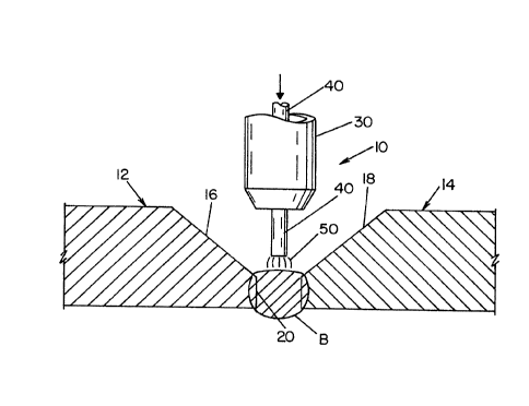
In FIGURES 1 and 2 the pipe welding operation 10 is used to weld the pipe
sections 12, l4.having
a gap or open root 20 defined by tapered ends 16, 18, which ends are spaced
apart in accordance with
standard practice. The invention relates to the laying or deposition of the
first weld bead B in the
open root 20 by moving torch 30 around the pipe sections 12, 14 while the
torch follows a path
determined by the joint including root pass 20 at the bottom. In accordance
with the invention, a
wire 40 is fed at a selected rate through torch 30 toward root pass 20 while
welding current is passed
through the welding wire. The welding current creates an arc 50 as shown in
FIGURE 1 to melt the
-4-
CA 02314058 2000-07-18
L-12288
end of the advancing wire 40. As the wire is converted to a molten ball and
moved toward bead B,
a short circuit condition 52 is created as shown in FIGURE 2. This condition
causes a transfer of
molten metal from wire 40 to bead B. By moving torch 30 around open root 20,
this alternate arcing
condition and short circuit, metal transfer condition is continued. Welding
wire 40 has a special
composition. In accordance with the invention, it includes .06 - .15% by
weight of carbon, .90 -
1.40% by weight manganese, and .45 - .57% by weight silicon. In addition, the
wire includes
phosphorous, copper, stainless steel alloys, such as nickel, chrome,
molybdenum and vanadium, and
sulfur. In accordance with the present invention, wire 40 has a sulfur
percentage level maintained
in the specific range of .O1 S - .035% by weight. In a like manner, a trace
amount of phosphorous
is maintained in electrode 40. This trace amount is in the general range of
.006 - .008% by weight
and in accordance with the invention is always maintained at a level of less
than .015%. By
selecting and maintaining the composition of electrode 40, the advantages set
forth in the
introductory portion of this disclosure are realized. In addition, the ST T
welding process used in
combination with the specifically tailored electrode or welding wire is
critical. This welding process
used in accordance with the present invention is illustrated in FIGURES 3 and
4.
Referring now to FIGURES 3 and 4, the waveform W shown in FIGURE 4 is the STT
waveform created by the STT welder 100. This welder uses either a down chopper
or the illustrated
high speed, switching inverter 102 with a' DC input link having a positive
terminal 110 and a
negative terminal 112. In the field, the STT welder or power supply is
normally driven by a motor
generator; however, for simplicity, the input is illustrated as a rectifier
120 with a three phase input
power supply 122. The output 130 of STT welder is used to melt and deposit
electrode or-welding
wire 40 from a supply reel 132 advancing toward the open root 20 beriveen pipe
sections 12, 14 by
an electric motor 134 driven at a selected speed to control the wire speed
rate. In accordance with
standard STT practice, a relatively small inductor 140 is provided in output
130 with a freewheeling
diode 142 for the purposes of stabilizing the output welding procedure to
follow the waveform.
Wave form W, as shown in FIGURE 4, is controlled by the voltage on control
line 150 of inverter
102. This input or control line has a voltage determined by the output of
pulse width modulator 152
-5-
CA 02314058 2000-07-18
L-12288
operated at a rate exceeding 18 kHz by oscillator 160. Preferably the rate of
pulses on line 150 is
substantially greater than 20 kHz. Thus, inverter 102 outputs a rapid
succession of current pulses
created by oscillator 160 at a very high rate. Pulse width modulator 152
determines the width of
each current pulse from inverter 120 to output 130. In accordance with
standard STT practice, wave
shape W is determined by control circuit 200. This standard practice is shown
generally in FIGURE
of Stava 5,742,029. The wave shape control circuit 200 has an output with a
voltage that is
compared to the voltage on line 202. This feedback voltage is representative
of the arc current
through wire 40. A voltage representing arc voltage is generated by current
sensor 204 receiving
current information from shunt 206. ~Vaveform W as used in the present
invention is a single
10 welding cycle repeated successively as wire 40 is melted and deposited
between pipe sections 12,
14. Waveform W, in accordance with STT technology includes a short circuit
portion including a
metal transfer short circuit pulse 210 where the current is dropped when the
metal being transferred
is electrically necked down and then ruptured. After the rupture or "fuse"
waveform 'V transitions
into an arc or plasma portion, comprising a plasma boost 220 having a
controlled maximum current
220a, a tailout portion 222 and a background portion 224. Background current
is provided for
sustaining the arc until the next short circuit at point 226 when the molten
metal ball on the wire 40
shorts against pipe sections 12, 14 or against the bead B filling root pass
20.
In accordance with a limited aspect of the present invention, the composition
of welding wire
40 includes less than 0.50% by weight copper and less than 0.50% of the
stainless steel alloys. After
the open root is closed by bead B, the welding method shifts to a rapid
filling of the remainder of
the joint. This is accomplished either by using a solid wire with gas or,
preferably, by using a cored
welding wire with a flux so shield gas is not necessary. Preferably the STT
welder or power supply
is also used in the joint filling operation where a number of high deposition
passes are made around
the pipe.
-6-