Note: Descriptions are shown in the official language in which they were submitted.
CA 02314127 2003-11-24
- 1 -
CAN STRUCTURE AND MANUFACTURING METHOD THEREOF
BACKGROUND OF THE INVENTION
Field of the invention
The present invention relates to a can structure for
a catalytic converter which is a device for purifying harmful
combustion gasses exhausted from internal combustion engines and
the like, and to a manufacturing method thereof.
Description of the Related Art
Currently, ceramic honeycomb catalytic converters are
widely used as automobile exhaust gas purifying devices.
Environmental issues in recent years along with even
stricter exhaust gas restrictions are requiring that catalysts
be able to function immediately following starting the engine
when the exhaust gas is still cool, i.e., cold starts.
Accordingly, a step being taken is to reduce the thickness
of the partitions of the catalyst carrier to 1/2 to 1/6 of the
conventional thickness, so as to lower the thermal capacity of
the catalyst carrier and speed up the temperature rising of the
catalyst carrier, along with improving engine performance due
to reductions in pressure loss.
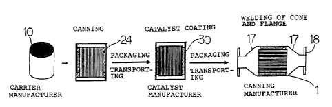
Normally, a ceramic honeycomb catalytic converter is
manufactured as shown in Fig. 4.
First , the carrier manufacturer packages a ceramic carrier
10 (ceramic honeycomb structure) which has passed inspection,
CA 02314127 2003-11-24
- 2 -
and sends it to a catalyst manufacturer.
The catalyst manufacturer unpacks this, performs
processes such as causing the ceramic carrier 10 (ceramic
honeycomb structure) to hold the catalyst (i.e., catalyst
coating), thermal processing, inspection, etc., thereby forming
a catalyst carrier 25 (ceramic honeycomb catalyst carrier),
which is then packaged and sent to a can manufacturer.
The can manufacturer unpacks this and attaches a
holding material 13 to the catalyst carrier 25 so as to fix within
a metal case 11 by compressed fixing (canning) , thus forming a
canned catalyst carrier 30, following which joining parts such
as a cone portion 17 and flange 18 and the like are welded to
the canned catalyst carrier 30 as necessary, thereby completing
a catalytic converterl(ceramic honeycomb catalytic converter).
Now, in the event that a ceramic honeycomb structure having
the thickness of the partitions at around 1/2 to 1/6 of. the
conventional thickness is used as the above catalyst carrier,
there has been the problem that the ceramic honeycomb structure
easily cracks or chips during transporting, the catalyst
carrying process, the canning process, and handling in each of
the processes (e.g. , packaging, unpacking, placing on or taking
off of the mechanical facilities (conveyers, chucking, canning,
etc.)).
In order to solve this problem, the present Inventors have
proposed a new ceramic honeycomb catalytic converter
CA 02314127 2003-11-24
- 3 -
manufacturing process using a can structure (an article
wherein a ceramic honeycomb structure before carrying the
catalyst is fixed inside a metal case beforehand, using a holding
material).
However, the above canningstructure has been uneconomical,
since at the time of carrying the catalyst (i.e., catalyst
coating) , expensive catalyst is carried by not only the ceramic
honeycomb structure but also the holding material which does not
take part in the catalytic reaction with the exhaust gas.
SUMMARY OF THE INVENTION
The present invention has been made in light of the present
situation, and accordingly, it is an object thereof to provide
a can structure and a manufacturing method thereof, capable
of preventing chipping and cracking of the ceramic honeycomb
structure at the time of transporting, the catalyst carrying
process, the canning process, and handling in each of the
processes, without allowing the holding material to carry
expensive catalyst at the time of carrying the catalyst.
That is, according to the present invention, there is
provided a canning structure which comprises a ceramic honeycomb
structure; said honeycomb structure being free of catalyst, a
metal case and a holding material, and said ceramic honeycomb
structure being canned in said metal case and being held by said
holding material thereto;
CA 02314127 2003-11-24
- 4 -
wherein an impermeable layer is provided on at least one
edge plane in the longitudinal direction of the holding material.
The length of the impermeable layer here is preferably 10
mm or less, more preferably 7 mm or less, and even more preferably
5 mm or less.
Also, the impermeable layer preferably has surface
pressure properties which are approximately the same as those of
the holding material, or less.
Further, at least one end face of the holding material
having the impermeable layer is preferably on approximately the
same plane as an end plane of the ceramic honeycomb structure.
Also, with the present invention, the impermeable layer
preferably comprises at least one edge plane in the longitudinal
direction of the holding material to which an impermeable
material has adhered.
Now, the form of the impermeable material is preferably
that of a thin film, or of a strand of circular, quadrangular,
or arbitrary cross-section.
Also, the impermeable material is preferably formed of
resin such as plastic, rubber, paper, cloth, or fiber.
Further, with the present invention, the impermeable layer
preferably comprises at least one end face in the longitudinal
direction of the holding material impregnated with impermeable
matter such as resin, oil or fat, etc.
Incidentally, with the present invention, the holding
CA 02314127 2003-11-24
- 5 -
material is preferably a non-intumescent ceramic fiber mat.
Also, according to the present invention, there is a method
for manufacturing a canning structure having a ceramic honeycomb
structure free of catalyst, a metal case, and a holding
material, and said ceramic honeycomb structure being canned in
said metal case and being held by said holding material thereto;
the method comprising forming an impermeable layer by adhering
an impermeable material on at least one end face of the holding
material in the longitudinal direction, such that at least one
end face of said impermeable layer of the holding material and
an end face of the ceramic honeycomb structure are provided on
approximately the same plane.
Further, according to the present invention, there is
provided a method for manufacturing a canning structure
having a ceramic honeycomb structure free of catalyst, a metal
case and, a holding material, and said ceramic honeycomb
structure being canned in said metal case and being held by said
holding material thereto;
the method comprising impregnating an impermeable matter
so as to form an impermeable layer on at least one end face in
the longitudinal direction of a holding material, such that at
least one end face of said impermeable layer of the holding
material and an end face of the ceramic honeycomb structure are
provided in approximately the same plane.
CA 02314127 2003-11-24
- 6 -
BRIEF DESCRIPTION OF THE DRAWINGS
Fig. lA is a plan view illustrating an example of the
can structure according to the present invention;
Fig. 1B is a rear view of that shown in Fig. lA;
Fig. 1C is a front view of that shown in Fig. lA;
Fig. 1D is a cross-sectional view of that shown in Fig.
lA;
Fig. 2A is a plan view illustrating another example of the
can structure according to the present invention;
Fig. 2B is a rear view of that shown in Fig. 2A;
Fig. 2C is a front view of that shown in Fig. 2A;
Fig. 2D is a cross-sectional view of that.shown in Fig.
2A;
Fig. 3 is a schematic diagram illustrating an example of
the manufacturing process of the ceramic honeycomb catalytic
converter using the can structure according to the present
invention; and
Fig. 4 is a schematic diagram illustrating an example of
the manufacturing process of a conventional ceramic honeycomb
catalytic converter.
DETAILED DESCRIPTION OF THE PREFERRED EMBODIMENTS
The can structure according to the present invention
CA 02314127 2003-11-24
_ 7
comprises a ceramic honeycomb structure before carrying a
catalyst fixed beforehand within a metal case by a holding
material, having an impermeable layer on at least one edge plane
in the longitudinal direction of the holding material.
Thus, not only can chipping and cracking of the ceramic
honeycomb structure be prevented at the time of transporting,
the catalyst carrying process, the canning process, and handling
in each of the processes, but also the holding material can be
prevented from wastefully carrying expensive catalyst at the
time of carrying the catalyst.
Next , the present invention will be described in further
detail with reference to the drawings.
Figs. lA through 2D illustrate examples of the can
structure according to the present invention. Figs. lA and 2A
are plan views , Figs . 1B and 2B are rear views , Figs . 1C and 2C
are front views , and Figs . 1D and 2D are cross-sectional views .
As shown in Figs. lA through 1D, the can structure
according to the present invention comprises a ceramic honeycomb
structure 10 before carrying a catalyst, fixed beforehand within
a metal case 11 by a holding material 13 , having an impermeable
layer 70 on an edge plane 13a in the longitudinal direction of
the holding material.
At this time, the length t of the impermeable layer 70 for
the can structure 24 according to the present invention
should be a minimal length, preferably 10 mm or less, more
CA 02314127 2003-11-24
preferably 7 mm or Less, and even more preferably 5 mm or less.
Also, in order to prevent damage such as cracking from
occurring in the ceramic honeycomb structure due to the
impermeable layer 70 at the time of canning, the plane pressure
of the impermeable layer as to the ceramic honeycomb structure
should be low, and accordingly, the impermeable layer 70
preferably has plane pressure properties which are approximately
the same as those of the holding material 13, or less.
Further, as shown in Fig. 1, the edge plane 15a of the
holding material at the side of the impermeable layer is
preferably on approximately the same plane as the edge plane l0a
of the ceramic honeycomb structure.
Accordingly, the can structure 24 can be caused to
carry the catalyst in a sure manner, thereby allowing the
catalyst carrying process to be optimized:
Now, in the case of causing the can structure 24 shown
in Fig . 1 to carry the catalyst , there is the need to make sure
that there is the impermeable layer 70 at the upper part of the
can structure 24, which is the side from which the catalyst
slurry is poured in.
To this end, the impermeable layer 70 is more preferably
provided to both longitudinal ends 13a and 13b of the holding
material 13, as shown in Figs. 2A through 2D.
Thus, the can structure according to the present
invention is capable of suppressing the catalyst slurry
CA 02314127 2003-11-24
_ g _
containing the catalyst component from flowing to the holding
material in the catalyst carrying process.
Next, with the can structure according to the present
invention, the impermeable layer preferably comprises at least
one edge plane in the longitudinal direction of the holding
material to which an impermeable material has adhered, so as to
facilitate ease of forming an impermeable layer.
Here, the form of the impermeable material used with the
present invention is preferably that of a thin film, or of a rope
with a circular, quadrangular, or arbitrary cross-section.
Also, the impermeable material used with the present
invention is not particularly restricted so long as it has
excellent impermeability and adhesion, and is preferably formed
of resin such as plastic, rubber, paper, cloth, or like fiber.
Further, with the can structure of the present
invention, the impermeable layer preferably comprises at least
one edge plane in the longitudinal direction of the holding
material impregnated with impermeable matter such as oils and
fats (e. g., grease).
Thus , the impermeable layer and the holding material can
be wound onto the perimeter surface of the ceramic honeycomb
structure at the same time, so the can process can be
simplified.
Here, the impermeable layer used with the present
invention is preferably combustible.
CA 02314127 2003-11-24
- 10 -
This is in order to easily remove the impermeable layer
which has become no longer necessary, by a thermal process ( 500
to 700° C ) following carrying the catalyst ( catalyst coating ) .
Further, in addition to the above advantages, the can
structure according to the present invention is capable of
protecting the ceramic honeycomb structure from external shock
and vibrations , and accordingly chipping and cracking of ceramic
honeycomb structures (particularly of those with thin walls
( thickness of partitions : 0 . 10 mm or thinner) ) can be prevented
at the time of transporting, the catalyst carrying process, the
canning process, and handling in each of the processes.
The can structure according to the present invention
is preferably of an arrangement wherein the metal case has a
stuffing structure or a tourniquet structure.
This is because the plane pressure distribution at the time
of canning is uniform, which allows prevention of engine exhaust
gasses leaking, corrosion of the holding material~due to the
exhaust gasses, and rattling, damage, etc., of the ceramic
honeycomb structure due to engine vibrations, thereby improving
reliability.
Particularly, in the event that the metal case has a
tourniquet structure, not only is the plane pressure
distribution uniform, but canning can be performed at a constant
plane pressure regardless of irregularities in the diameter of
the ceramic honeycomb structure, which is particularly
CA 02314127 2000-07-18
- 11 -
preferable for ceramic honeycomb structures with low mechanical
strengths (particularly, those with thin walls).
Also, the holding material used with the present invention
is preferably a non-intumescent ceramic fiber mat.
This allows the maximum plane pressure at the time of
canning due to irregularities in the diameter of the ceramic
honeycomb structure to be reduced, and further to prevent damage
to ceramic honeycomb structures (particularly, those with thin
walls ) , since an excessive pressure is not generated at the time
10~ of heating as with expanding mats.
Now, the non-intumescent ceramic fiber mat used with the
present invention is made up of at least one selected from the
following group; alumina, mullite, silicon carbide, silicon
nitride, and zirconia. This non-intumescent ceramic fiber mat
1~~ is formed of ceramic fibers wherein the fiber diameter is 2 um
or greater by less than 6 um, such that application of an initial
plane pressure of 2 kgf/cm2 at room temperature and then raising
the temperature to 1,000°C results in generation of a plane
pressure of at least 1 kgf/cm2, and also has the compression
20 properties in that there is little increase or decrease within
the actual usage temperature range of the catalytic converter.
The partition thicknessof the ceramic honeycombstructure
used with the present invention is preferably 0. 10 mm or thinner
(more preferably, 0.08 mm or thinner).
2°.i This is in order to cause the catalyst to function at cold
CA 02314127 2003-11-24
- 12 -
starts as well, by lowering the thermal capacity of the catalyst
carrier and speeding up the temperature rising of the catalyst
carrier, along with improving engine performance due to
decreasing pressure loss.
Next, an example of a manufacturing processing for the
ceramic honeycomb catalytic converter using the can structure
according to the present invention will be described with
reference to Fig. 3.
First, the carrier manufacturer provides uses a ceramic
carrier 10 (ceramic honeycomb structure) which has passed
inspection, and forms a can structure 24, which is then packaged
and sent to a catalyst manufacturer.
At this time, a holding material 15 having an impermeable
layer is wrapped onto the ceramic carrier IO ( ceramic honeycomb
structure), which is compressed and fixed within a metal case
11 (i.e., canned), thereby forming the can structure 24 (See
Figs. lA through 2D).
Also, the can structure 24 can be manufactured by
wrapping a holding material 13 onto the ceramic carrier 10
(ceramic honeycomb structure), which is compressed and fixed
within a metal case 11 (i.e., canned), following which an
impermeable material is caused to adhere to at least one edge
plane in the longitudinal direction of the holding material, so
as to form an impermeable layer 70 (See Figs. lA through 2D).
The catalyst manufacturer unpacks this, performs the
CA 02314127 2003-11-24
- 13 -
processes such as causing the can structure 24 to carry the
catalyst (i.e., catalyst coating), thermal processing,
inspection, etc., thereby forming a canned catalyst carrier 30,
which is then packaged and sent to a canning manufacturer.
Incidentally, the catalyst carrying process is performed
by pouring a catalyst slurry in from the upper part of the can
structure 24 while suctioning the catalyst slurry out from the
lower part of the can structure 24, thereby causing the
ceramic honeycomb structure to be dipped in catalyst slurry such
that the can structure 24 carries the catalyst.
At this time, the holding material provided with the
impermeable layer can prevent the catalyst slurry from flowing
out to the holding material. Also, the impermeable layer can
be easily removed in the thermal process, if combustible.
The canning manufacturer unpacks this and welds joining
parts such as a cone portion 17 and flange 18 and the like to
the canned catalyst carrier 30 as necessary, thereby completing
the catalytic converter (ceramic honeycomb catalytic converter
1).
As described above, this method for manufacturing ceramic
honeycomb catalytic converters is capable of protecting the
ceramic honeycomb structure from external shock and vibrations
as compared with conventional manufacturing methods (see Fig.
4), and accordingly chipping and cracking of ceramic honeycomb
structures can be markedly prevented at the time of transporting,
CA 02314127 2003-11-24
- 14 -
the catalyst carrying process , the canning process , and handling
in each of the processes.
Next , the present invention will be described in further
detail with reference to embodiments, but it should be noted that
the present invention is by no means restricted to these
embodiments.
Embodiment
A ceramic carrier (ceramic honeycomb structure)
manufactured of cordierite, with a diameter of 106 mm, length
of 114 mm, partition thickness of 0.03 mm, and 465 cells/cm2,
was prepared. A non-intumescent ceramic fiber mat ("MAFTEC"
(product name), manufactured by MITSUBISHI CHEMICAL
CORPORATION) of 1, 200 g per 1 m2 was further wrapped thereupon,
as a holding material.
A rope-shaped impermeable member(material: polyethylene)
was caused to adhere to one end 13a of the holding material in
the longitudinal direction, thereby forming a ceramic honeycomb
structure wrapped with a holding material having an impermeable
layer 70 of 2 mm in length ( see Figs . lA through 1D ) , which was
pressed into a stainless-steel can (metal case) with an inner
diameter of 114 mm, length of 124 mm, and thickness of 1.5 mm,
using a tapered jig for pressing.
Next, twenty of such can structures obtained with the
embodiment were placed in the ceramic honeycomb catalytic
converter manufacturing process shown in Fig. 3.
CA 02314127 2003-11-24
- 15 -
Consequently, the catalyst slurry was completely
prevented from flowing out to the holding material in the
catalyst carrying (catalyst coating) process.
Also, absolutely no cracking or chipping of the ceramic
honeycomb structures was observed at any point in the above
manufacturing process.
A can structure was fabricated under the same
conditions as the above embodiment, using holding material
without the impermeable layer 70, and twenty of such were placed
in the ceramic honeycomb catalytic converter manufacturing
process shown in Fig. 3.
Consequently, the catalyst slurry flowed out to the
holding material in the catalyst carrying process, such that 8%
of the catalyst slurry used was held by the holding material and
hence wasted.
Incidentally, absolutely no cracking or chipping of the
ceramic honeycomb structures was observed at any point in the
above manufacturing process.
Second Comt~arative Exam~3e
Twenty ceramic carriers (ceramic honeycomb structures)
manufactured of cordierite, with a diameter of 106 mm, length
of 114 mm, partition thickness of 0.06 mm, and 140 cells/cm2,
were prepared, and were placed in the ceramic honeycomb catalytic
converter (pressing canning) manufacturing process shown in Fig.
CA 02314127 2003-11-24
- 16 -
4.
Consequently, the rate of cracking or chipping of the
ceramic honeycomb structures throughout the above manufacturing
process reached 25%.
lamination of Embodiment and Comsar~itive Examples
The embodiment has impermeable layers on both edges in the
longitudinal direction of the holding material, and thus the
catalyst slurry can be prevented from flowing out to the ceramic
fiber mat at the time of.carrying the catalyst.
Also, in comparison with the comparative examples, the
embodiment is capable of protecting the ceramic honeycomb
structure from external shock and vibrations, and accordingly
chipping and cracking of Ceramic honeycomb structures at the time
of transporting, the catalyst carrying process, the canning
process, and handling in each of the processes, can be markedly
reduced.
Thus, according to the can structure and manufacturing
method thereof according to the present invention, the catalyst
slurry is prevented from flowing out to the holding material,
and chipping and cracking of ceramic honeycomb structures can
be prevented at the time of transporting, the catalyst carrying
process, the canning process, and handling in each of the
processes.