Language selection

Search

Patent 2314145 Summary

Third-party information liability

Some of the information on this Web page has been provided by external sources. The Government of Canada is not responsible for the accuracy, reliability or currency of the information supplied by external sources. Users wishing to rely upon this information should consult directly with the source of the information. Content provided by external sources is not subject to official languages, privacy and accessibility requirements.

Claims and Abstract availability

Any discrepancies in the text and image of the Claims and Abstract are due to differing posting times. Text of the Claims and Abstract are posted:

  • At the time the application is open to public inspection;
  • At the time of issue of the patent (grant).
(12) Patent: (11) CA 2314145
(54) English Title: ELECTRICAL CONNECTOR
(54) French Title: CONNECTEUR ELECTRIQUE
Status: Deemed expired
Bibliographic Data
(51) International Patent Classification (IPC):
  • H01R 13/502 (2006.01)
  • H01R 4/50 (2006.01)
(72) Inventors :
  • MCCARTHY, DALE C. (United States of America)
(73) Owners :
  • CENTERPIN TECHNOLOGY, INC. (United States of America)
(71) Applicants :
  • CENTERPIN TECHNOLOGY, INC. (United States of America)
(74) Agent: PERRY + CURRIER
(74) Associate agent:
(45) Issued: 2005-12-20
(86) PCT Filing Date: 1998-06-11
(87) Open to Public Inspection: 1999-07-08
Examination requested: 2003-06-06
Availability of licence: N/A
(25) Language of filing: English

Patent Cooperation Treaty (PCT): Yes
(86) PCT Filing Number: PCT/US1998/012136
(87) International Publication Number: WO1999/034483
(85) National Entry: 2000-06-12

(30) Application Priority Data:
Application No. Country/Territory Date
08/999,356 United States of America 1997-12-29

Abstracts

English Abstract


An electrical connector (10) for
coupling to a plurality of insulated electrical
conductors (28, 30) has a housing (11) and
a housing cover both having a plurality of
bores therein, at least a portion of each
bore being tapered. A plurality of
electrical conductive prongs each having one end
attached to the housing and extending
axially into each housing bore for receiving
the end of an insulated electrical conductor.
Attaching means attach the housing cover
to the housing over a plurality of
compression collars. Each compression collar has
a bore extending axially therethrough to
allow for insertion of a wire therethrough and
into the housing bore and onto a pointed
prong.


French Abstract

La présente invention concerne un connecteur électrique (10) destiné à coupler plusieurs conducteurs électriques isolés (28,30). Ledit connecteur électrique comprend un boîtier (11) et un couvercle de boîtier traversés chacun par plusieurs alésages possédant chacun au moins une partie conique. Plusieurs broches électroconductrices possédant chacune une extrémité fixée au boîtier s'étendent axialement jusque dans chaque alésage de boîtier afin de recevoir l'extrémité d'un conducteur électrique isolé. Des moyens de fixation permettent de fixer le couvercle de boîtier sur le boîtier, au-dessus de plusieurs colliers de serrage. Chaque collier de serrage est traversé par un alésage axial qui permet l'insertion d'un fil jusque dans l'alésage de boîtier, et sur une broche pointée.

Claims

Note: Claims are shown in the official language in which they were submitted.


12

CLAIMS:

I claim:

1. An electrical connector (35,75) for coupling
to a plurality of insulated electrical conductors
(36,76) comprising:
a housing (37,80) having a housing cover (38,81),
said housing and cover having a plurality of bores
(44,77) therein, at least a portion of each bore being
tapered (51,85);
a plurality of electrical conductive pointed
prongs (50,86), one of said plurality of pointed
prongs being attached to said housing (37,80) in each
said bore (44,77) therein, said pointed prong (50,86)
having one end portion protruding axially into one
said housing bore for receiving the end of an
insulated electrical conductor (43,92);
attaching means (40,78) for attaching said cover
to said housing bore;
a plurality of compression collars (52,82), each
having an opening extending axially therethrough for
insertion of a wire therethrough, and each said
collar (52,82) having a compression portion (54,83)
thereon for wedging into said housing tapered portion
(51,85) upon said cover being attached to said
housing driving each said collar into the tapered
portion of one said bore whereby placing a collar
(52,82) into each said housing bore (44,77) and
inserting a wire (36,76) into each housing bore
through the inserted collar and tightening the cover
(38,81) to said housing (37,80), clamps said collar
onto a wire placed therein, whereby a plurality of
insulated wires (37,80) can be rapidly connected to an


13
electrical connector (35,75) without removing the
insulation from the end of the wire.

2. An electrical connector (35,75) for coupling
to a plurality of insulated electrical conductors
(36,76) in accordance with claim 1 in which each said
collar (52,82) has an angled expandable and
compressible portion (54,83) which expands upon
insertion of a wire (37,80) therethrough and
compresses onto an inserted wire when said housing
cover (38,81) is attached to said housing (37,80).

3. An electrical connector (35,75) for coupling
to a plurality of insulated electrical conductors
(36,76) in accordance with claim 1 in which each said
collar (52,82) has a plurality of angled fingers
(54,83) thereon and said housing cover (38,81) has a
plurality of bores (44,77) therethrough, each said
bore having said tapered portion (51,85) therein to
compress upon said collar fingers being wedged
thereagainst.

4. An electrical connector (35,75) for coupling
to a plurality of insulated electrical conductors
(36,76) in accordance with claim 2 in which each said
collar (52,82) has a plurality of split portions
(55,84) in the end thereof to form a plurality of
segments which expand by the insertion of a wire
(37, 80) and compress by the attaching of said cover
(38, 81) to said housing (37,80).


14

5. An electrical connector (35,75) for coupling
to a plurality of insulated electrical conductors
(36,76) in accordance with claim 4 in which said
collar is a one piece polymer collar.

6. An electrical connector (75) for coupling to
a plurality of insulated electrical conductors (76)
in accordance with claim 6 in which said housing (80)
has a generally cylindrical shape.

7. An electrical connector (35) for coupling to
a plurality of insulated electrical conductors (36)
in accordance with claim 5 in which said housing (37)
has a generally rectangular shape.


15

8. An electrical connector (75) for coupling to
a plurality of insulated electrical conductors (76)
comprising:
a housing (80) having a plurality of bores (85)
therein, each said bore having a tapered portion
therein;
a plurality of electrical conductive center pins
(86) attached to said housing (80) and each said
center pin extending into one said housing bore (85)
for receiving the end of an insulated electrical
conductor (76);
a housing cover (81) removably attached to said
housing (80) and having a plurality of bores (77)
therethrough, each said bore having a plurality of
compression collars (82) therein, each sized to fit
into one said housing bore and each said collar (82)
having a bore extending therethrough for insertion
of a wire (76) therein, and each said collar (82)
having a compressible portion (83) compressible upon
driving said collar (82) into one said housing bore
tapered portion to drive said compressional portion
(83) against a wire (76) inserted therein; and
a housing cover attaching cap (78) covering a
portion of said housing cover (81) and removably
attached to said housing (80) for compressing said
cover (81) onto said housing (80);
whereby placing said collar (82) into said
housing tapered bore (85) clamps said collar onto a
wire (76) placed therein,


16

9. An electrical connector (75) for coupling to
a plurality of insulated electrical conductors (76) in
accordance with claim 9 in which each said collar has
tapered fingers (83) and is sized to accept difference
size wires.

10. An electrical connector (75) for coupling
to a plurality of insulated electrical conductors (76)
in accordance with claim 8 in which each said collar
(82) has an expandable and compressible portion (83)
which expands upon insertion of a wire (76) through
said collar bore and compresses onto the inserted wire
when said collar is driven into said housing.

11. An electrical connector (75) for coupling to
a plurality of insulated electrical conductors (76) in
accordance with claim 11 in which each said collar
(82) has a plurality of splits (84) in the end thereof
to form a plurality of collar segments (83) which
expand by the insertion of a wire therethrough and
compress by driving said segments into a housing (80)
tapered portion (85).

12. An electrical connector (75) for coupling to
a plurality of insulated electrical conductors (76) in
accordance with claim 8 in which said housing (80) is
generally cylindrical in shape.


17

13. An electrical connector (60,95) for coupling
to an insulated electrical conductor (70,71,103)
comprising:
a housing (63,99) having a bore (67,100)
therein;
a housing cap (68,69,104) removably attached to
said housing (63,99) and having a bore therethrough,
said cap bore having a tapered portion (105) therein,
and being aligned with said housing bore (67,100) when
said housing cap (68,69,104) is attached to said
housing (63, 99);
an electrical conductive center pin (101)
attached to said housing (63,99) and extending into
said housing bore (67,100) for receiving the end of an
insulated electrical conductor (70,71,103);
a compression collar (61,62,97) sized to fit into
said housing bore (67,100) and said cap (68,69,104)
having an angled compressible portion (105)
compressible upon driving said collar (61,62,97) into
said housing cover bore tapered portion to drive said
compression collar (61,62,97) against a wire
(70,71,103) inserted therein whereby placing an
insulated wire (70,71,103) through said cap
(68,69,104) into said housing bore and through said
collar (61,62,97) and tightening said cap (68,69,104)
clamps said collar (61,62,97) onto the wire, whereby
a wire (70,71,103) can be rapidly connected to an
electrical connector (60,95).


18

14. An electrical connector (60) for coupling to
an insulated electrical conductors (70,71) in
accordance with claim 13 in which said housing (63)
has two bores therein, each having a conductive center
pin extending thereinto and has a pair of compression
collars (61,62) for attaching two wires (70,71) to
said electrical connector (60).

15. An electrical connector (60,95) for~
coupling to an insulated electrical conductors
(70,71,103) in accordance with claim 13 in which said
collar (61,62,97) has an expandable and compressible
portion (72,97) which expands upon insertion of a wire
(70,71,103) through said collar bore and compresses
onto an inserted wire when said collar is driven into
said housing (63,99).

16. An electrical connector (60,95) for coupling
to an insulated electrical conductors (70,71,103) in
accordance with claim 15 in which said collar
(61,62,97) has a plurality of fingers (72,97) on the
end thereof which expand by the insertion of a wire
(70,71,103) therethrough and compress by driving said
fingers into a housing tapered portion.

17. An electrical connector (95) for coupling to
an insulated electrical conductors (103) in accordance
with claim 13 in which said housing (99) is a battery
terminal.

18. An electrical connector (60,95) for coupling
to an insulated electrical conductors (70,71,103) in
accordance with claim 15 in which said collar
(61,62,97) is a one piece polymer collar.


19

19. An electrical connector (60,95) for coupling
to a plurality of insulated electrical conductors
(70,71,103) in accordance with claim 15 in which said
housing (66,99) is generally cylindrical in shape.

Description

Note: Descriptions are shown in the official language in which they were submitted.


CA 02314145 2000-06-08
WO 99/34483 PCT/US98/12136
ELECTRICAL CONNECTOR
1 BACKGROUND OF THE INVENTION
2
3 The present invention relates to electrical
4 connectors and especially to an electrical connector
for coupling to an insulated electrical conductor
6 without stripping the end of the insulated electrical
7 conductor. This application is an improvement to my
8 prior U.S. patent for Electrical Connector, U.S.
9 Patent 5,704,814, dated January 6, 1998.
In the past, a wide variety of electrical wire
11 connectors have been provided for connecting to wire
12 ends. In a typical connector, the end of the wire is
13 stripped of insulation and the bare wire is inserted
14 into a connector where it can be soldered or clamped
or otherwise attached to the connector. It is also
16 common to tin the wire ends by coating the wire end
Z7 with solder and a wide variety of connectors have been
18 provided which removably hold the wire to the
19 connector.
Typical connectors are seen in audio systems,
21 such as in hi-fi speakers in which a wire end is
22 stripped of the insulation and is inserted in an
23 opening and a threaded nut is threaded down onto the
24 wire, the nut can be loosened for removing the wire.
Other audio speakers include spring clamps which
26 allows a wire end to be stripped of insulation and
27 inserted into an opening while lifting the spring
28 connector clamp and then releasing the spring
29 connector clamp onto the wire. Relifting of the
spring connector clamp allows the removal of the wire
31 end. Other commonly used connectors allow a stripped
32


CA 02314145 2000-06-08
WO 99/34483 PG"T/US98112136
2
1 wire end to be inserted into a connector or into both
2 ends of a connector and then clamped with pliers to
3 collapse a conductive sleeve onto the wire. This type
4 of connector can be insulated or not as desired since
it is made of a malleable metal in which the
6 collapsing onto the stripped wire end provides the
7 necessary electrical contact.
8 In contrast to these various types of wire
9 connectors, the present invention deals with a wire
connector that does not require the insulation to be
11 stripped and also provides, in some embodiments, for
12 the insertion of the insulated wire end in a manner to
13 lock the wire end in place inside the bore of a wire
14 connector.
Prior wire connectors can be seen in the
16 following U.S. Patents. The Chang patent,
17 No.4,013,333, for a wire connector having two
18 concentric sockets adapted to be assembled one into
19 the other and in which the inner socket has a
conductive needle mounted therein for sliding a wire
21 end into each end of the connector and which also uses
22 a spike pressed in two holes in the sleeves to
23 penetrate the coating of the wire ends. In the U.S.
24 patent to Danner, No. 3,860,320, a dangles cathode
cable assembly is connected to a ball-like cathode
26 member by stripping the end portion of the cable and
27 inserting the end portion into a sleeve which is
28 pressed into an undersized tapered socket and which
29 has a pointed pin therein. In the U.S. patent to
Friedhelm, No. 4,786,760, a cable connector fox
31 piezoelectric cable has an insulated cable end which
32 is inserted into a sleeve. In the U.S. patent to
33 Berman, No. 4,091,233, an electrical connector and a
34 method of connecting an electrical cable to the


CA 02314145 2000-06-08
WO 99134483 PCTIUS98/12136
3
1 connector is provided for connecting one or more
2 insulated electrical cords or cables together. The
3 insulated cable ends can be inserted into the
4 receptacles on either end and onto a prong of
electrically conductive material so that the prong is
6 an electrical contact with the wire of an insulated
7 cord end. A container of adhesive material on the
8 end of the receptacle is released from the container
9 to create a physical bond between the cord and the
connector to hold the cord within the connector. In
11 my prior U.S. patent No. 5,403,201 an electrical
12 connector is coupled to an insulated electrical
13 conductor without stripping the end of the insulated
14 conductor. The insulated wire is held with a spring
clamp which allows the wire to be released.
16 In the Komada Patent No. 4,374,458 a method of
17 connecting a co-axial cable to a connector having a
18 plurality of connections. The Herrington Patent No.
19 916,313 is for a spark plug having a spark plug wire
connector on the end thereof. The Despard patent No.
21 3,097,035 is for another electric cable connector for
22 use between sections of flexible multi-conductor cable
23 as used with portable electric power consuming
24 equipment and to a fixed power outlet. The Polidori
patent No. 3,633,147 has a connector for underground
26 utility applications.
27 The present invention utilizes an electrical
28 connector for coupling to an insulated electrical
29 conductor end which is inserted into a bore through
a compression collar in a housing bore to drive a
31 prong into the conductor end and to releasably clamp
32 and hold the insulated wire end within the electrical
33 connector with the compression collar.
34


CA 02314145 2000-06-08
WO 99134483 PCTIUS98I12136
4
1 SUN~1ARY OF THE INVENTION
2
3 An electrical connector for coupling to a
4 plurality of insulated electrical conductors includes
a housing having a housing cover, said housing and
6 cover having a plurality of bores therein, at least a
7 portion of each bore having a tapered portion
8 therein. A plurality of electrical conductive prongs,
9 one of which is attached to the housing in each bore
with each said pointed prong extending axially into
11 each housing bore for receiving the end of an
12 insulated electrical conductor. Attaching means
13 attach the housing cover to the housing. A plurality
14 of compression collars, each having a bore extending
axially therethrough, allows the insertion of a wire
16 therethrough and into the housing bore and onto the
17 pointed prong. Each collar has an angled compression
18 portion for wedging into the housing tapered portion
19 upon the cover being attached to the housing and
compressible upon driving the collar into the tapered
21 portion of the bore whereby placing a plurality of
22 insulated wires can be rapidly connected to an
23 electrical connector without removing the insulation
24 from the end thereof . The collar has the bore thereof
tapered with an expandable and compressible end formed
26 with a plurality of angled compression fingers and can
27 be of different sizes so that different size wires can
28 be inserted therethrough and guided onto the connector
29 prong. The collar can be a one piece polymer or brass
member.
31
32
33
34


CA 02314145 2000-06-08
WO 99134483 PCT/US98/12136
1 BRIEF DESCRIPTION OF THE DRAWINGS
2
3 Other objects, features, and advantages of the
4 present invention will be apparent from the written
5 description and the drawings in which:
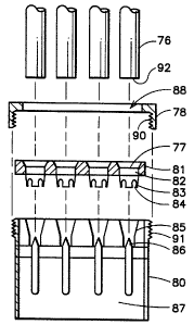
6 Figure 1 is a perspective view of an electrical
7 connector in accordance with the present invention;
8 Figure 2 is a sectional view taken through the
electrical connector of Figure 1;
Figure 3 is an exploded rear perspective view of
11 the electrical connector of Figures 1 and 2;
12 Figure 4 is an exploded front perspective view of
13 the electrical connector of Figures 1-3;
14 Figure 5 is a perspective view of another
electrical connector for connecting a plurality of
16 conductors simultaneously thereto;
17 Figure 6 is an exploded view of the connector of
18 Figure 5;
19 Figure 7 is a perspective view of an electrical
connector for connecting to wires in series;
21 Figure 8 is an exploded perspective of the
22 connector of Figure 7;
23 Figure 9 is a perspective view of another
24 connector for connecting a plurality of electrical
conductors thereto;
26 Figure 10 is an exploded sectional view taken on
27 the line 10-10 of Figure 9; and
28 Figure 11 is an exploded sectional view of an
29 electrical battery terminal connector in accordance
with the present invention.
31
32
33
34


CA 02314145 2000-06-08
WO 99/34483 PCT/US98/12136
6
1 DESCRIPTION OF THE PREFERRED EMBODIMENT
2
3 Referring to the drawings and Figures 1-4, an
4 electrical connector 10 has a housing 11 having a rear
housing portion 12 and a front housing portion 13
6 having a flange 14 extending therearound. The housing
7 may be made of a polymer or plastic material and the
8 front housing piece 13 has a pair of threaded bores 15
9 extending therein having threads 16. The bores, as
seen in Figure 2, each have a tapered end portion 17
11 therein and an electrical connecting center pin or
12 prong 18 extending therein from one end. The prong is
13 attached to the rear cover 12 and has a wire
14 connecting eye 20 extending out of the back 12 of the
connector housing. A threaded collar member 21 has a
16 handle 22 and external threads 23 which engage the
17 internal threads 16 of the bores 15.
18 As seen in Figure 4, each collar 21 has a
19 threaded tapered end 25 having a plurality of slits
26 therein. The collar 21 can be made of a polymer
21 material and has the slits 26 forming the tapered
22 portion 25 to allow the collar to expand as different
23 size wires are pushed through the collar bore 27 to
24 guide the wire through the center of the collar 21
along the axis thereof. The wire is guided onto the
26 center pin or protruding prong 18 so that the still
27 insulated piece of wire can be inserted thereonto to
28 provide an electrical connection. Once the wire is
29 inserted, the electrical connection is made by sliding
the conductor portion of the wire onto the connecting
31 prong 18. The collar 21 handle 22 can be rotated to
32 thread the external threads 23 further into the
33 internal threads 16 so that the end 26 of the collar
34 21 is compressed by the angled surface 17 of the


CA 02314145 2000-06-08
WO 99/34483 PCf/US98/12136
7
1 connector bore 15. As it pushes further in, the
2 annular angled surface 17 compresses the split collar
3 end 26 to clamp down onto the wire member 28 or 30 of
4 Figure 1 to firmly clamp the wire member into position
extending onto the electrical connector.
6 In operation, a wire of any size, such as wires
7 28 or 30, can be inserted into the bore 27 until it is
8 pushed onto the center pin 18 in the housing 11. The
9 threaded collar 21 can then be rotated to compress the
end 25 into the wedging or narrowing surface 17 to
11 compress onto the wire 28 or 3o to lock the wire to
12 the connector. Thus, a wide variety of wire sizes can
13 be inserted into a universal electrical connector
14 merely by sliding it into the bore 17 which makes the
electrical contact without removing the insulation
16 from the wire end and then clamping down upon the wire
17 by rotating the collar handle 22. The wire can be
18 removed simply by loosening the collar 21 by rotating
19 the handle 22 in a counterclockwise direction to
thereby loosen the compression of a collar end to
21 allow the wire to be pulled loose.
22 The present connection is advantageous in
23 situations such as in connecting of audio speakers
24 where different size wires are frequently used
including some of the larger cables. Thus, the
26 electrical connector is universal as to a wide variety
27 of wire sizes and allows the rapid connection by
28 merely sliding the wire in and onto the center pin
29 electrical connector conductor and, with a couple of
twists of the collar, can threadedly clamp the cable
31 onto the connector so that it cannot be easily pulled
32 out without loosening the collar 21. The conductors
33 31 inside the insulation 32 of the wire 28 is thus
34 guided directly onto the connector pin 18 for a


CA 02314145 2000-06-08
WO 99/34x83 PCT/US98/12136
8
1 complete electxical connection without removing any of
2 the insulation 32 from the end of the wire 28.
3 Referring to Figures 5 and 6, a multi-wire
4 electrical connector 35 has a plurality of insulated
conductors 36 attached thereto. An electrical
6 connector 35 has a housing or body 37 in an elongated
7 rectangular shape and has a cover 38 with a housing
8 37. The cover is attached to the housing with a
9 plurality of threaded fasteners 40. Each electrical
conductor 36 has a central conductor 41 surrounded by
11 insulating sheet 42. As seen in Figure 6, each
12 electrical wire 36 has been cut with a smooth edge 43
13 through the insulation and the conductor. The cover
14 38 has a plurality of openings 44 for inserting one
conductor 36 within each opening 44. The cover also
16 has the openings 45 for the screws 40. The housing in
17 turn has a plurality of openings 46 which align with
18 each opening 44 when the threaded fasteners 40 attach
19 the cover 38 through the openings 45 and into the
threaded openings 47. A plurality of electrical
21 connectors 48 extend from the bottom of the housing
22 and each has a central prong or pin 50 extending into
23 the bore 46. Each bore 46 also has a tapered surface
24 51. A plurality of clamping or compressing collars 52
each has a generally cylindrical portion 53 and a
26 plurality of fingers 54 spaced by a plurality of slots
27 55 and which may be at an angle to the cylindrical
28 portion 53. Each collar 52 is inserted into one
29 tapered portion 51 of the bore 46 and the cover 38 is
partially attached with the screws 40 to the housing.
31 Each conductor 36 can then be inserted through the
32 cover openings 44 through the collars 52 where they
33 will expand the fingers 54 and then be inserted into
34 the bores 46 where the prongs 50 drive into the


CA 02314145 2000-06-08
WO 99134483 PCT/US98112136
9
1 insulation and into the conductor in the center
2 thereof. The collars 52 can be made of an inexpensive
3 insulating polymer material which allows the expansion
4 of the fingers 54 or can be of a conductive metal, as
desired, since the collars do not come into contact
6 with the conducting center wire. Once each wire is
7 inserted, the screws 40 can be tightened down driving
8 each collar 32 pushing against the top edge 56 which
9 drives the fingers 54 against the tapered surface 51
to compress the fingers directly against the outer
11 insulation 42 of each conductor 36, thus clamping all
12 of a plurality of individual insulated conductors 36
13 simultaneously.
14 Turning to Figures 7 and 8, an electrical
conductor 60 uses the collars 61 and 62, which is the
16 same as the collars 52 in Figures 5 and 6. In this
17 embodiment, a central housing 63 has external threads
18 64 on one side and external threads 65 on the other
19 side thereof. The center prong 66 extends all the way
through the housing 63 and provides a prong on either
21 side thereof in the bores 67. Threaded caps 68 and 69
22 are threaded onto the housing 63 threads 64 and 65
23 against the collars 61 and 62 so that a pair of
24 conductors 70 and 71 slid therein expand the fingers
72 of each collar. Driving the insulated wire 70 and
26 71 onto the prong 66 and tightening the caps against
27 the collars within each side of the housing 63
28 connects conductors 70 and 71 together. This is
29 accomplished without stripping either wire and by
merely sticking a wire in each end and tightening the
31 two caps.
32 Turning to Figures 9 and 10, an electrical
33 connector 75 has a plurality of insulated electrical
34 conductors 76 extending thereinto through a plurality


CA 02314145 2000-06-08
WO 99134483 PCTNS98I12136
1 of openings 77 within a cover 81 attached to a housing
2 80 with a threaded open cap 78. The cap 78 clamps
3 onto the cover surface 81 which has a plurality of
4 collars 82 built thereinto, as seen in Figure 10.
5 Each collar 82 has a plurality of flexible fingers 83
6 spaced by a plurality of slots 84. The housing 80 has
7 a plurality of tapered openings 85 therein, each
8 having a prong or center pin 86 extending thereinto
9 and then extending into the hollow housing portion 87.
10 In operation, the cap portion 78, which has an open
11 center portion 88 and internal threads 90, is threaded
12 onto the external threads 91 on the housing 80 driving
13 the multiple collar member 81 into the tapered bores
14 85. Once the top clamp 81 is loosely attached, each
of the insulators 76 having the ends 92 smoothly cut
16 off and inserted through an openings 77 spreading the
17 fingers 83 of each collar and pushed onto an
18 electrical conducting prong 86. The threaded collar
19 78 is then tightened to drive all of the collars
angled fingers 83 against the tapered opening 85 and
21 into each of the conductors 76 extending therethrough
22 to clamp and hold each of the conductors 76
23 simultaneously.
24 Turning to Figure 11, another embodiment of the
present invention shows a battery electrical connector
26 95 having a collar 96 aimilar to the collar 52 of
27 Figure 6 having a plurality of flexible or ductile
28 fingers 97 separated by a plurality of slots 98. The
29 connector housing 99 has a bore 100 therein with a
prong 101 extending into the bore and then has a
31 battery terminal opening 102 which can be clamped onto
32 a battery terminal. The collar 96 is inserted into
33 the bore 100 and electrical conductor 103 is inserted
34 through the collar onto the prong 101 and through the


CA 02314145 2000-06-08
WO 99134483 PGTIUS98/12136
11
1 cap 104. The cap 104 may have a tapered surface 105
2 therein which drives against the collar 96 fingers 97
3 when the threaded cap 104 threads 106 are threaded
4 onto the internal threads 107 in the bore 100 of the
connector housing 99.
6 It should be clear at this time that an
7 electrical connector uses a common compression cover
8 for connecting a plurality of conductors
9 simultaneously or for connecting a single conductor to
certain types of terminals. The electrical connector
11 allows a rapid connection of an insulated wire end
12 without stripping the wire or tinning the end of the
13 wire and leaves a fully insulated connector which can
14 be rapidly attached, released, and replaced and which
can be used with a wide variety of wire sizes. It
16 should, however, also be clear that the present
17 invention is not to be limited to the forms shown
18 which are to be considered illustrative rather than
19 restrictive.

Representative Drawing
A single figure which represents the drawing illustrating the invention.
Administrative Status

For a clearer understanding of the status of the application/patent presented on this page, the site Disclaimer , as well as the definitions for Patent , Administrative Status , Maintenance Fee  and Payment History  should be consulted.

Administrative Status

Title Date
Forecasted Issue Date 2005-12-20
(86) PCT Filing Date 1998-06-11
(87) PCT Publication Date 1999-07-08
(85) National Entry 2000-06-12
Examination Requested 2003-06-06
(45) Issued 2005-12-20
Deemed Expired 2014-06-11

Abandonment History

There is no abandonment history.

Payment History

Fee Type Anniversary Year Due Date Amount Paid Paid Date
Registration of a document - section 124 $100.00 2000-06-12
Application Fee $150.00 2000-06-12
Maintenance Fee - Application - New Act 2 2000-06-12 $50.00 2000-06-12
Maintenance Fee - Application - New Act 3 2001-06-11 $50.00 2001-05-30
Maintenance Fee - Application - New Act 4 2002-06-11 $100.00 2002-05-30
Maintenance Fee - Application - New Act 5 2003-06-11 $150.00 2003-06-04
Request for Examination $400.00 2003-06-06
Maintenance Fee - Application - New Act 6 2004-06-11 $200.00 2004-06-10
Maintenance Fee - Application - New Act 7 2005-06-13 $200.00 2005-05-20
Final Fee $300.00 2005-10-05
Maintenance Fee - Patent - New Act 8 2006-06-12 $200.00 2006-05-03
Maintenance Fee - Patent - New Act 9 2007-06-11 $200.00 2007-06-08
Maintenance Fee - Patent - New Act 10 2008-06-11 $450.00 2009-05-13
Maintenance Fee - Patent - New Act 11 2009-06-11 $250.00 2009-05-13
Maintenance Fee - Patent - New Act 12 2010-06-11 $250.00 2010-06-02
Maintenance Fee - Patent - New Act 13 2011-06-13 $250.00 2011-06-08
Maintenance Fee - Patent - New Act 14 2012-06-11 $250.00 2012-06-07
Owners on Record

Note: Records showing the ownership history in alphabetical order.

Current Owners on Record
CENTERPIN TECHNOLOGY, INC.
Past Owners on Record
MCCARTHY, DALE C.
Past Owners that do not appear in the "Owners on Record" listing will appear in other documentation within the application.
Documents

To view selected files, please enter reCAPTCHA code :


To view images, click a link in the Document Description column. To download the documents, select one or more checkboxes in the first column and then click the "Download Selected in PDF format (Zip Archive)" or the "Download Selected as Single PDF" button.

List of published and non-published patent-specific documents on the CPD .

If you have any difficulty accessing content, you can call the Client Service Centre at 1-866-997-1936 or send them an e-mail at CIPO Client Service Centre.


Document
Description 
Date
(yyyy-mm-dd) 
Number of pages   Size of Image (KB) 
Cover Page 2000-09-06 1 48
Claims 2000-06-12 8 269
Representative Drawing 2000-09-06 1 10
Drawings 2000-06-12 3 132
Description 2000-06-12 11 524
Abstract 2000-06-12 1 56
Representative Drawing 2005-03-17 1 9
Cover Page 2005-11-23 1 39
Correspondence 2005-10-05 1 49
Assignment 2000-06-08 6 310
PCT 2000-06-12 4 195
Prosecution-Amendment 2000-06-12 1 20
Correspondence 2003-03-24 2 57
Correspondence 2003-03-28 1 13
Correspondence 2003-03-28 1 16
Fees 2003-06-04 1 50
Prosecution-Amendment 2003-06-06 1 54
Correspondence 2004-06-01 1 23
Fees 2004-06-10 1 49
Correspondence 2005-06-22 1 10
Prosecution-Amendment 2005-05-20 1 25
Correspondence 2005-05-19 1 48
Fees 2005-05-20 1 53
Correspondence 2005-06-22 4 177
Fees 2006-05-03 1 50
Correspondence 2007-03-30 1 24
Fees 2007-06-08 1 53
Fees 2009-05-13 1 57
Fees 2009-05-13 2 65
Fees 2010-06-02 1 65
Fees 2011-06-08 1 57
Correspondence 2012-06-01 3 98
Correspondence 2012-06-13 1 13
Correspondence 2012-06-13 1 15