Language selection

Search

Patent 2314206 Summary

Third-party information liability

Some of the information on this Web page has been provided by external sources. The Government of Canada is not responsible for the accuracy, reliability or currency of the information supplied by external sources. Users wishing to rely upon this information should consult directly with the source of the information. Content provided by external sources is not subject to official languages, privacy and accessibility requirements.

Claims and Abstract availability

Any discrepancies in the text and image of the Claims and Abstract are due to differing posting times. Text of the Claims and Abstract are posted:

  • At the time the application is open to public inspection;
  • At the time of issue of the patent (grant).
(12) Patent: (11) CA 2314206
(54) English Title: A PROCESS FOR COATING PRIMARY PRODUCTS AND A DEVICE FOR CARRYING OUT THE PROCESS
(54) French Title: PROCEDE D'ENROBAGE DE PRODUITS PRIMAIRES ET DISPOSITIF FAISANT APPEL A CE PROCEDE
Status: Deemed expired
Bibliographic Data
(51) International Patent Classification (IPC):
  • B05D 7/22 (2006.01)
  • A61M 5/31 (2006.01)
  • B05C 7/00 (2006.01)
  • B05C 7/08 (2006.01)
(72) Inventors :
  • VETTER, UDO J. (Germany)
(73) Owners :
  • ARZNEIMITTEL GMBH APOTHEKER VETTER & CO. RAVENSBURG (Germany)
(71) Applicants :
  • ARZNEIMITTEL GMBH APOTHEKER VETTER & CO. RAVENSBURG (Germany)
(74) Agent: KIRBY EADES GALE BAKER
(74) Associate agent:
(45) Issued: 2006-07-04
(22) Filed Date: 2000-07-21
(41) Open to Public Inspection: 2001-01-24
Examination requested: 2000-09-26
Availability of licence: N/A
(25) Language of filing: English

Patent Cooperation Treaty (PCT): No

(30) Application Priority Data:
Application No. Country/Territory Date
199 34 841.3-45 Germany 1999-07-24

Abstracts

English Abstract

The invention provides a process and a device for coating the inside of syringe barrels (1) of little volume with a silicone film. A coating ring (3) is moistened with silicone oil, the coating ring (3) is then inserted in the syringe barrel (1) and guided axially along the inside wall. During this process, the coating ring (3) completely abuts against the inside wall. When the coating ring (3) is finally withdrawn, a wiper ring (4) located behind it in the direction of motion removes the excess silicone oil, thereby creating a homogeneous silicone film of even thickness. In a preferred embodiment, the coating ring (3) and the wiper ring (4) are both arranged on a siliconizing mandrel (2) at an axial distance from each other, whereby the siliconizing mandrel (2) has a channel (5) in axial direction for feeding the silicone oil. Its one end opens into the area of the coating ring (3), whilst its other end is arranged in such a way that it can be connected to a feeder tube (6).


French Abstract

Cette invention fournit un processus et un dispositif pour enduire l'intérieur de boîtes de seringues (1) de petit volume avec une pellicule en silicone. Un anneau d'enduit (3) est humidifié avec de l'huile de silicone, l'anneau d'enduit (3) est ensuite placé à l'intérieur de la boîte à seringues (1) et dirigé de manière axiale le long du mur intérieur. Au cours du processus, l'anneau d'enduit (3) est plaqué contre le mur intérieur. Lorsque l'anneau d'enduit (3) est retiré, une lingette (4) située derrière l'anneau d'enduit est activée pour retirer l'excès d'huile de silicone, ce qui permet de créer une pellicule en silicone homogène d'une épaisseur régulière. Idéalement, l'anneau d'enduit (3) et la lingette (4) sont placés sur le mandrin de silicone (2) à une distance axiale, le mandrin de silicone (2) est doté d'un canal (5) en direction axiale pour alimenter l'huile de silicone. Il révèle une zone de l'anneau d'enduit (3), tandis que l'autre extrémité est placée de manière à être connectée à un tuyau d'alimentation (6).

Claims

Note: Claims are shown in the official language in which they were submitted.


-5-

Claims:

1. A process of coating an inside wall of an elongated syringe body, the
method
comprising the steps of:
supplying at least an outer surface of a coating ring with a coating of
silicone oil while;
displacing the coating ring from a rear end to a front end of the body with
the coating ring in continuous annular engagement with the inside wall thereof
so
as to transfer the oil from the coating ring to the inside wall; and
thereafter
displacing a wiper ring from the front end to the rear end of the body with
the wiper ring in continuous annular engagement with the inside wall so as to
scrape excess silicone oil from the inside wall,
wherein the coating ring and the wiper ring are arranged on a mandrel at an
axial distance from each other, the mandrel having an axial channel with a
first end
to coat the coating ring and a second end connectable to a source of silicone
oil.
2. A process according to claim 1, wherein the coating is 2 micrometers thick.
3. A process according to claim 1 or 2, wherein the wiper ring enters the
syringe
body before the coating ring during insertion.
4. A process according to any one of claims 1 to 3, wherein the coating ring
and the
wiper ring are O-rings.
5. A process according to claim 3 or 4, wherein the coating ring and the wiper
ring
are each arranged in respective ring grooves on the mandrel, and the first end
of
the axial channel opens into a ring groove of the coating ring.


-6-

6. A process according to claim 5, wherein the ring groove of the coating ring
has
two or more entry channels arranged regularly radially around the
circumference of
the ring groove.
7. A process according to claim 5 or 6, wherein the ring groove for the wiper
ring can
accommodate at least one support ring located on a side of the wiper ring away
from the coating ring.
8. A device for coating an inside wall of an elongated syringe body, the
device
comprising;
a coating ring, which can be moistened with silicone oil and inserted into
and withdrawn from the syringe body, and dimensioned to maintain continuous
annular engagement with the inside wall thereof, so as to transfer the oil
from the
coating ring to the inside wall;
a wiper ring, arranged axially distant from the coating ring for removing
excess silicone oil by wiping the inside wall when passed in the withdrawal
direction; and
a mandrel holding the coating ring and the wiper ring at an axial distance
from each other and having an axial channel with a first end to coat the
coating
ring and a second end connectable to a source of silicone oil.
9. A device according to claim 8, wherein the wiper ring enters the syringe
body
before the coating ring during insertion.
10. A device according to claim 8 or 9, wherein the coating ring and the wiper
ring are
O-rings.


-7-

11. A device according to claim 9 or 10, wherein the coating ring and the
wiper ring
are each arranged in respective ring grooves on the mandrel, and the first end
of
the axial channel opens into a ring groove of the coating ring.
12. A device according to claim 11, wherein the ring groove of the coating
ring has
two or more entry channels arranged regularly radially around the
circumference of
the ring groove.
13. A device according to claim 11 or 12, wherein the ring groove for the
wiper ring
can accommodate at least one support ring located on a side of the wiper ring
away
from the coating ring.

Description

Note: Descriptions are shown in the official language in which they were submitted.


CA 02314206 2003-02-14
-1-
A process for coating primary products and a device for carrying out the
process.
Technical Pield
The invention refers to a process for COatIIlg pI'lnlal'y prOduCtS, in
particular for coating the
inside of syringe barrels with a silicone film. The invention also concerns a
device for
carrying out this process.
Background of the Invention
With pre-filled syringes and carpule systems, rubber plugs are used to seal
off the contained
pharmaceutical substance. Syringe or carpule barrels are normally made of
Class 1
hydrolytic glass. During the injection process, the rubber stoppers that are
arranged in the
syringe or carpule barrel are pressed towards the cannula end by means of a
plunger rod.
With this medical application of the active substance, the rubber plugs must
be able to be
easily displaced in the glass vessel. In order to achieve these minor
displacement forces, the
rubber plug and the inside of the glass barrel must both be coated with
silicone oil.
It is desirable to apply silicone homogeneously to the interior surface of the
glass vessel and
ensure an even coating. However, it is necessary to apply the silicone
sparingly in order to
prevent the cannula from becoming blocked with excess silicone oil during the
injection
process and to prevent the silicone oil from mixing with the substance being
injected.
Summate of the Invention
The object of the invention is to provide a process to coat the inside of a
syringe barrel with
silicone in such a way that an even, homogeneous coating can be achieved as
well as
simultaneously ensuring that no excess silicone oil adheres to the inside of
the glass barrel.


CA 02314206 2003-02-14
-2-
In accordance with one aspect of the present invention there is provided a
process for coating
the interior of a tubular substrate with a thin film of a liquid, the process
comprising:
supplying at least an outer surface of a coating ring with a coating of
silicone oil while;
displacing the coating ring from a rear end to a front end of the body with
the coating ring in
continuous annular engagement with the inside wall thereof so as to transfer
the oil from the
coating ring to the inside wall; and thereafter displacing a wiper ring from
the front end to the
rear end of the body with the wiper ring in continuous annular engagement with
the inside
wall so as to scrape excess silicone oil from the inside wall, wherein the
coating ring and the
wiper ring are arranged on a mandrel at an axial distance from each other, the
mandrel having
an axial channel with a first end to coat the coating ring and a second end
connectable to a
source of silicone oil.
In accordance with another aspect of the present invention there is provided a
device for
coating the interior of a tubular substrate with a thin film of a liquid, the
device comprising: a
coating ring, which can be moistened with silicone oil and inserted into and
withdrawn from
the syringe body, and dimensioned to maintain continuous annular engagement
with the
inside wall thereof, so as to transfer the oil from the coating ring to the
inside wall; a wiper
ring, arranged axially distant from the coating ring for removing excess
silicone oil by wiping
the inside wall when passed in the withdrawal direction; and a mandrel holding
the coating
ring and the wiper ring at an axial distance from each other and having an
axial channel with
a first end to coat the coating ring and a second end connectable to a source
of silicone oil.
Detailed Description of the Invention
A process that provides the solution is characterized in that a coating ring
is moistened with
silicone oil and is then inserted in the syringe barrel and guided axially
along the inside wall
(whereby the coating ring completely abuts against the inside wall), and in
that, when the
coating ring is finally withdrawn, a wiper ring located behind it in the
direction of motion
removes the excess silicone oil, thereby creating a homogeneous silicone film
of even
thickness.


CA 02314206 2003-02-14
-2a-
The advantage of the invention is that an even moistening is achieved by the
movement of the
coating ring towards the cannula end of the barrel and that, when the coating
ring is
withdrawn, the wiper ring moving behind it ensures that the excess silicone
oil is removed
from the glass barrel.
In an advantageous and optimized embodiment of the process, the silicone film
that is formed
has a suitable thickness of approximately 2 micrometers.
In regard to the device, the object is achieved by means of a coating ring and
a wiper ring that
are both arranged on a siliconizing mandrel at an axial distance from each
other, whereby the
siliconizing mandrel has a channel in axial direction for feeding the silicone
oil, its one end
opening into the area of the coating ring, whilst the other end is arranged in
such a way that it
can be connected to a feeder tube.


CA 02314206 2000-07-21
-3-
In an advantageous further embodiment of the invention, the coating ring and
the wiper ring
are designed as O-rings. Within the framework of the invention, it is
advantageous if the
coating ring and the wiper ring are arranged in a ring groove in the
siliconizing mandrel,
whereby the channel for feeding the silicone oil opens into the ring groove of
the coating
ring.
In order to achieve an even coating of silicone oil on the coating ring, it
has been proven to
be advantageous when two ~or more entry channels, arranged evenly in radial
direction around
the circumference of the ring groove, enter into the ring groove of the
coating ring.
Finally, within the framework of the invention, a provision can be made so
that the ring
groove for the wiper ring is wider in order to accommodate at least one
support ring that is
located on the side opposite the coating ring.
The invention is described in more detail below in an embodiment illustrated
in the drawings:
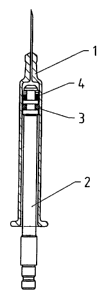
Fig. 1 shows an illustration in simplified form of the device for coating
syringe barrels.
Fig. 2 shows a detail from Fig. :l, namely a syringe barrel with an inserted
siliconizing
mandrel.
Fig. 3 shows a detail of the siliconizing mandrel.
Fig. 4 shows the object according to Fig. 3, however without a coating or
wiper ring,
partially in section.
The purpose of the device shown in the diagram is to coat primary products, in
particular to
coat the inside of syringe barrels 1 of low volume with a silicone film.
In order to achieve this, the device has a siliconizing mandrel 2 on which a
coating ring 3 and
a wiper ring 4 are arranged at an axial distance to each other. The
siliconizing mandrel 2 has
a channel 5 in axial direction for feeding the silicone oil, its one end of
the channel 5 opening
into the area of the coating ring 3, whilst the other end is arranged in such
a way that it can be


CA 02314206 2005-04-07
-4-
connected to a feeder tube 6. As can be seen in Fig. l, this feeder tube 6
leads to a pump 7
that is connected to a silicone supply container 9 via another tube 8. This
silicone supply
container 9 can also be pressurized via a pressure control valve 10.
In the starting position shown in Fig. l, the coating ring 3 is first
moistened with silicone oil,
then the siliconizing mandrel 2 is inserted into the syringe barrel 1 by means
of an actuating
device (not shown in detail in the drawing) and the coating ring 3 is guided
in axial direction
along the inside wall of the syringe barrel 1, whereby the coating ring 3
abuts completely
against the inside wall so that, to great extent, an even and complete coating
with silicone oil
is achieved on the inside wall.
Following this, the siliconizing mandrel 2 is withdrawn, whereupon the wiper
ring 4, which
is arranged in the direction of motion behind the coating ring 3, removes the
excess silicone
oil; thereby creating a homogenous, silicone film of even thickness. The
design of the wiper
ring 4 and the pressure with which it pressed against the wall are adjusted in
such a way that
the remaining silicone film is approximately 2 micrometers thick.
As shown particularly well in Fig. 3, the coating ring 3 and the wiper ring 4
are designed as
O-rings. Furthermore, the coating ring 3 and the wiper ring 4 are each
arranged in a ring
groove 11 on the siliconizing mandrel 2, and the channel 5 for feeding the
silicone oil opens
into the ring groove 11 of the coating ring 3.
In order to moisten the coating ring 3 as evenly as possible, two entry
channels 12 in radial
direction open into the ring groove 11 of the coating ring 3. However, it is
just as conceivable
to provide several entry channels 12 evenly arranged around the circumference.
As can be seen in Fig. 3, the ring groove 11 for the wiper ring 4 is wider and
serves to
accommodate two support rings 13 that are arranged on the side opposite the
coating ring 3.

Representative Drawing
A single figure which represents the drawing illustrating the invention.
Administrative Status

For a clearer understanding of the status of the application/patent presented on this page, the site Disclaimer , as well as the definitions for Patent , Administrative Status , Maintenance Fee  and Payment History  should be consulted.

Administrative Status

Title Date
Forecasted Issue Date 2006-07-04
(22) Filed 2000-07-21
Examination Requested 2000-09-26
(41) Open to Public Inspection 2001-01-24
(45) Issued 2006-07-04
Deemed Expired 2014-07-22

Abandonment History

There is no abandonment history.

Payment History

Fee Type Anniversary Year Due Date Amount Paid Paid Date
Registration of a document - section 124 $100.00 2000-07-21
Application Fee $300.00 2000-07-21
Request for Examination $400.00 2000-09-26
Maintenance Fee - Application - New Act 2 2002-07-22 $100.00 2002-05-08
Maintenance Fee - Application - New Act 3 2003-07-21 $100.00 2003-04-29
Maintenance Fee - Application - New Act 4 2004-07-21 $100.00 2004-04-28
Maintenance Fee - Application - New Act 5 2005-07-21 $200.00 2005-05-13
Final Fee $300.00 2006-04-10
Maintenance Fee - Application - New Act 6 2006-07-21 $200.00 2006-04-26
Maintenance Fee - Patent - New Act 7 2007-07-23 $200.00 2007-04-16
Maintenance Fee - Patent - New Act 8 2008-07-21 $200.00 2008-05-14
Maintenance Fee - Patent - New Act 9 2009-07-21 $200.00 2009-07-06
Maintenance Fee - Patent - New Act 10 2010-07-21 $250.00 2010-04-15
Maintenance Fee - Patent - New Act 11 2011-07-21 $250.00 2011-04-01
Maintenance Fee - Patent - New Act 12 2012-07-23 $250.00 2012-04-12
Owners on Record

Note: Records showing the ownership history in alphabetical order.

Current Owners on Record
ARZNEIMITTEL GMBH APOTHEKER VETTER & CO. RAVENSBURG
Past Owners on Record
VETTER, UDO J.
Past Owners that do not appear in the "Owners on Record" listing will appear in other documentation within the application.
Documents

To view selected files, please enter reCAPTCHA code :


To view images, click a link in the Document Description column. To download the documents, select one or more checkboxes in the first column and then click the "Download Selected in PDF format (Zip Archive)" or the "Download Selected as Single PDF" button.

List of published and non-published patent-specific documents on the CPD .

If you have any difficulty accessing content, you can call the Client Service Centre at 1-866-997-1936 or send them an e-mail at CIPO Client Service Centre.


Document
Description 
Date
(yyyy-mm-dd) 
Number of pages   Size of Image (KB) 
Description 2000-07-21 4 186
Abstract 2000-07-21 1 25
Drawings 2000-07-21 2 26
Claims 2000-07-21 3 89
Description 2003-02-14 5 201
Claims 2003-02-14 3 97
Cover Page 2001-01-30 1 34
Claims 2004-06-08 3 77
Description 2005-04-07 5 206
Representative Drawing 2005-12-14 1 3
Cover Page 2006-06-06 1 39
Correspondence 2000-08-19 1 2
Assignment 2000-07-21 3 85
Prosecution-Amendment 2000-09-26 1 25
Assignment 2000-11-20 2 73
Prosecution-Amendment 2002-08-15 3 107
Prosecution-Amendment 2003-02-14 10 358
Prosecution-Amendment 2003-12-08 3 89
Prosecution-Amendment 2004-06-08 6 177
Prosecution-Amendment 2005-01-04 2 49
Prosecution-Amendment 2005-04-07 27 845
Correspondence 2006-04-10 1 40