Note: Descriptions are shown in the official language in which they were submitted.
CA 02314223 2000-06-13
WO 00/23675 PC"T/US99/19085
-1-
SUCTiON POWEREQ CLEANER
FOR SWIMMING POOLS
BACKGROUND OF THE 1NVENTION
This invention relates generatly to automatic pool cleaning devices
for travel over submerged surfaoes of a swimming pool or the like to pick up
and collect accumulated debris such as leaves, twigs, sand and silt. More
particularly, this invention relates to an improved pool cleaner of the so-
called suction or vacuum powered type, having means for cyclic interruption
of water flow to generate pulsating forces which cause the pool cleaner to
advance in steps over submerged floor and side wall surfaoes of a swimming
pool. The suction powered pool cleaner of the present invention includes
improved drive means for generating the requisite pulsating forces to drive
the cleaner in a reliable manner, with reduced risk of stalling upon ingestion
of large debris.
Pool deaner devioes are generally well known in the art for use in
maintaining residential and commercial swimming pools in a clean and
attractive condition. In this regard, swimming pools conventionally include
a water filtration system including a pump for drawing or suctioning water
from the pool for circulation through a filter canister having filter media
therein to remove and collect water-entrained debris such as leaves and
twigs as well as fine particulate including sand and silt. From the filter
canister, the water is recirculated to the pool via one or more return lines.
Such filtration system is nomnafly operated for several hours on a daily basis
and serves, in combination with traditional chemical treatments such as
chlorination or the like, to maintain the pool water in a clean and clear
sanitary state. However, the water filtration system is ineffective to filter
out
CA 02314223 2000-06-13
WO 00/23675 PCT/US99/19085
-2-
debris which settles onto submerged floor and side wall surfaces of the
swimming pool. In the past, settied debris has typically been removed by
coupling a vacuum hose to the suction side of the pool water filtration
system, such as by connecting the vacuum hose to a skimmer well located
near the water surface at one side of the pool, and then manually moving a
vacuum head coupled to the hose over the submerged pool surfaces to
vacuum settled debris directly to the filter canister where it is collected
and
separated from the pool water. However, manual vacuuming of a swimming
pool is a labor intensive task and is thus not typically performed by the pool
owner or pool cleaning service personnel on a daily basis.
Automatic pool cleaner devices have been developed over the
years for cleaning submerged pool surfaces, thereby substantially
eliminating the need for labor intensive manual vacuuming. Such automatic
pool cleaners typically comprise a relatively compact deaner housing or
head coupled to the pool water filtration system by a hose and including
water-powered means for causing the cleaner to travel about within a
swimming pool to dislodge and collect settled debris. In one form, the pool
cleaner is connected to the retum or pressure side of the filtration system
for
receiving positive pressure water which powers a turbine for rotatably driving
deaner wheels, and also functions by venturi action to draw settled debris
into a filter bag. See, for example, U.S. Patents 3,882,574; 4,558,479;
4,589,986; and 4,734,954. In another form, the pool cleaner is coupled to
the suction side of the filtration system, whereby water is drawn through the
pool cleaner to operate a drive mechanism for transporting the cleaner within
the pool while vacuuming settled debris to the filter canister of the pool
filtration system. See, for example, U.S. Patents 3,803,658; 4,023,227;
4,133,068; 4,208,752; 4,351,077; 4,642,833; 4,742,593; 4,761,848;
4,769,867; 4,807,318; 5,265,297; 5,315,728; 5,450,645; and 5,634,229.
While both positive pressure and suction powered pool cleaners
CA 02314223 2000-06-13
WO 00/23675 PCT/US99/19085
-3-
have proven to be generaiiy effective in cleaning settied debris and the like
from submerged pool surfaces, various customer preferences and
instaiiation considerations have been instrumental in causing an individual
customer to choose one cleaner type over the other. More specifically, by
comparison, positive pressure type cleaners are generally regarded as
providing better coliection of large debris such as leaves in a removable
filter
bag, to prevent such large debris from being drawn into and potentially
clogging the filter canister of the pooi water filtration system. Positive
pressure cleaners are also generally viewed as having superior random
travel for improved overall coverage of submerged pool surfaces. Moreover,
positive pressure cleaners normally exhibit better periodic back-up or
reverse function to resist entrapment in a sharp comer or the like within a
pool. However, such positive pressure cleaners often require a booster
pump and/or installation of an additional dedicated water return line to be
integrated into the filtration system, whereby the overall cost of installing
a
positive pressure cleaner particuiarly in an existing pool can be significant.
By contrast, a suction side cleaner normally can be coupled by a vacuum
hose directly into the existing skimmer well of a pool, for relatively
simpiified
connection to the suction side of the fiitration system In a pool that is not
equipped with a pre-installed suction side cleaner flow line. Moreover,
suction side cleaners are designed for operation without requiring an
additionai booster pump.' Accordingiy, suction side deaners have tended to
be somewhat less costly to install, in comparison with pressure side
cleaners. However, additional collection devices such as auxiiiary leaf
canisters and the like are generally required to capture large debris and
thereby prevent ingestion of large leaves and the like into the filter
canister
of the filtration system.
Most suction side cleaners cxureently available on the market utilize
a valve member typically in the form of a diaphragm or shuttie type valve
CA 02314223 2000-06-13
WO 00/23675 PCT/US99/19085
-4-
adapted for movement between open and closed positions at a cydic rate
to disrupt the suction flow in a manner creating pressure surges or
pulsations of sufficient magnitude to propel the deaner in a forward direction
in a series of incremental steps. However, this valve member has been
susceptible to clogging upon ingestion of debris vacuumed from a
submerged pool surface. Clogging of the valve member not only results in
undesirable stalling or interruption in cleaner operation, but also creates a
risk of cavitation and potential failure of the filtration system pump.
There exists, therefore, a significant need for further improvements
in pool cleaners of the suction powered type, particulariy with respect to
providing improved drive means for propelling the cleaner throughout a
swimming pool, with reduced risk of dogging in response to ingested debris.
Moreover, there exists a need for providing a suction powered pool cleaner
designed for enhanood randomness of travel over submerged surfaces of a
swimming pool. The present invention fulfills these needs and provides
further related advantages.
SUMMARY OF THE INVENTION
In eooordance with the invention, an improved pool cleaner of the '
type powered by a suction or vacuum source is provided for vacuuming
debris settled upon submerged floor and side wall surfaces of a swimming
pool or the like. The pool cleaner comprises a compact housing or head
adapted for connection,to a vacuum hose or the like coupled in tum to the
suction side of a conventianal pool water fiitration system. The cleaner head
defines a suction inlet through which water and debris are dnawn from an
underlying pool surface for flow to the vacuum hose. A main control valve
is pivotally mounted within the deaner head for oscillatory motion between
an open position and a substantially or nearly closed position relative to an
CA 02314223 2000-06-13
WO 00/23675 PCT/US99/19085
-5-
annuiar vaive. seat for intermittentiy disrupting the suction water flow to
create pressure flucbuations or puisations of sufficient magnitude to advance
the deaner head over a submerged pool surface in a series of incremental
steps.
More particulariy, the cleaner head has a downwardly open lower
foot defining the suction inlet, with a flexible perforated mat or disk
extending
radially ouhvardiy from the head in surrounding relation to the suction inlet.
Water is drawn radially iriwardiy beneath as well as downwardly through the
perforated disk to the suction inlet to sweep dirt and debris from an
underlying pool surface for flow into a plenum chamber formed within the
cleaner head. From the plenum chamber, the water and debris is drawn
further through a primary suction tube having an upstream end defining the
annular valve seat, and a downstream end coupled to the vacuum hose.
The main control valve is pivotally mounted within the plenum chamber for
swinging movement between a normal spring-ioaded open position spaced
substantiaiiy to one side of the valve seat, and a substantially closed
position to substantiaiiy disrupt water flow therethrough. In the preferred
form, a stop is provided to prevent complete closure of the main control
valve in the substantially closed position.
In operation, water drawn under vacuum through the primary
suction tube is effective to draw the main control valve from the normal
spring-loaded open position to the substantially closed position, whereupon
the water flow through the cleaner head is momentarity disrupted sufficiently
to enable the spring-loaded main control valve to return toward the open
position. As a result, the control valve is oscillated or reciprocated back-
and-forth between the open and dosed position in a cydic manner, to induce
a succession of pressure fluctuations or pulsations acting along the axis of
the primary suction tube. By orienting the primary suction tube to extend
forwardly and upwardly from the plenum chamber, these pressure
CA 02314223 2000-06-13
WO 00/23675 PCT/US99/19085
-6-
fluctuations or pulsations have a component of force which is effective to
displace tlo cleaner head generally along a forward path of travel in a series
of small steps.
In accordance with further aspects of the invention, the cleaner
head may additionally include a bypass suction tube having an upstream
end intersecting with the primary suction tube, and a lower or downstream
end disposed in close proximity to the perforated disk at a location spaced
forward from the foot of the cleaner head. This bypass suction tube provides
a secondary suction flow passage for vacuuming debris, particularly such as
relatively large debris drawn onto the disk but othennrise too large to pass
downwardly through the perforated disk to the suction inlet. A bypass valve
is mounted within the bypass suction tube and is resiliently biased to a
normal closed position. This bypass valve is oriented to open in response
to increased vacuum or negative pressure within the primary suction tube,
when the main control valve is in the substantially closed position.
Conversety, the spring-loaded bypass valve retums to the closed position in
response to decreased vacuum within the primary suction tube, when the
main control valve is in the open position. Accordingly, with this
construction, the bypass valve cycles between closed and open positions,
in opposition respectively to the open and closed positions of the main
control valve.
Substantially random travel of the pool cleaner over submerged
pool surfaces can be enhanced by forming an asymmetric pattem of
perforations In the-disk. With this design, vacuum-induced friction between
the disk and the underlying pool surface will be nonuniform at the laterally
opposed sides of the cleaner head, resulting in a nonlinear forward path of
cleaner travel. 'This nonlinear path of travel also may be produced by
mounting the flexible disk on the cleaner head in a manner permitting disk
rotation, and by inclusion of a part-circle and imperforate steering apron
CA 02314223 2000-06-13
WO 00/23675 PCT/US99/19085
-7-
projecting laterally from one side of the cleaner head to overlie a selected
arcuate segment of the disk to close the perforations therein.
Other features and advantages of the present invention wiii
become more apparent from the following detailed description, taken in
conjunction with the accompanying drawings which illustrate, by way of
example, the principles of the invention.
BRIEF DESCRIPTION OF THE DRAWINGS
The accompanying drawings illustrate the invention. In such
drawings:
FIGURE 1 is a perspective view iiiustrating a suction powered pool
cleaner oonstructed in accordance with the novel features of the invention,
and showirg the pool cleaner in operative reiation with a conventional pool
water fiitnation system;
. FIGURE 2 is an exploded perspective view of the pool cleaner
shown in FIG. 1, iiiustvting an outer housing shell in expioded relation to an
internai cleaner head;
FIGURE 3 is a left side eievationai view of the cieaner head;
FIGURE 4 is a rear eievationai view of the cleaner head;
FIGURE 5 Is an expioded perspective view of the cleaner head;
FIGURE 6 is a longitudinal vertical sectional view taken generally
on the line 6-6 of FIG. 4, and illustrating a main control valve in an open
position for regulating water flow through a primary suction tube;
FIGURE 7 is a iongitudinai vertical sectional view similar to FIG.
6, but depicting the main control valve is a substantially closed position;
FIGURE 8 is an enlarged exploded perspective view of a portion
of the cleaner head, showing assembly of the main control valve; and
FIGURE 9 is an exploded perspective view of a portion of the
CA 02314223 2000-06-13
WO 00/23675 PC.'T/US99/19085
-8-
cleaner head, showing assembly of a bypass valve for regulating water flow
through a bypass suction tube.
DETAILED DESCRIPTION OF-THE PREFERRED EMBODIMENTS
As shown in the exemplary drawings, an improved pool cleaner
referred to generally in FIGURE 1 by the reference numeral 10 is provided
for vacuuming debris such as leaves and twigs as well as small particulate
such as sand and silt settled onto submerged floor and side wall surfaces of
a swimming pool or the like. The pool cleaner 10 is powered by a suction or
vacuum souroe, such as by connection to a conventional pool water filtration
system 12 shown schematically in FIG. 1, by means of a vacuum hose 14.
In operation, water is drawn through the pool cleaner 10 in a manner for
water-bome vacuuming of debris settled onto submerged pool surfaces, and
wherein this flow of water provides a power source for driving a main control
valve 16 (FIGS. 5-8) in an oscillatory or reciprocatory manner to induce
pressure fluctuations or pulsations which drive the cleaner 10 along a
forward path of motion in a succession of incremental steps.
The pool cleaner 10 of the present invention is shown in FIG. I
coupled via the vacuum hose 14 to the suction side of a pump 18 forming
part of the pool water filtration system 12. In this regard, the vacuum hose
14 is normally connected between a cylindrical suction fitting 20 on the pool
cleaner and a skimmer well 22 mounted typically at one edge of the
swimming pool at a location generally at the water's surface. As is well
known in the art, the pump 18 draws pool water through the skimmer well 22
(as shown) for discharge flow through a filter canister 24 having a suitable
filter media (not shown) therein for filtering and collecting water-entrained
debris and particulate. From the filter canister 24, the water is recirculated
to the swimming pool typically through a plurality of return lines 26. When
CA 02314223 2000-06-13
WO 00/23675 PCT/US99/19085
-9-
the pool cieaner 10 is coupled by the vacuum hose 14 to the skimmer well
22, the pump 18 draws water under a vacuum or negative pressure through
the cleaner, wherein this suction water flow is utilized for powering the pool
cleaner to travel about in a substantially random pattem within the pool while
vacuuming debris settled onto submerged pool surfaces for collection within
the filter canister 24. Altemately, it will be recognized and understood that
some swimming pools may be equipped with a dedicated suction cleaner
flow line (not shown) coupled directly from the pool wall to the filtration
system 12, in which case the vacuum hose 14 would be coupled to said
suction flow line.
As shown in FIGS. I and 2, the pool cleaner 10 generally
comprises a relatively compact outer housing 28 encasing or mounted about
an inner housing or head 30. The head 30 includes a lower foot 32 defining
a downwardly open suction inlet 34 (FIG. 6) for vacuum inflaw of water-bome
debris, wherein the foot 32 is surrounded by a generally circular and
relatively flexible mat or disk 36 adapted to drape downwardly about the
suction inlet 34 to engage the underlying pool surface 38, as shown in dotted
lines in FIGS. 3 and 4. Water-bome debris is drawn through the suction
inlet 34 (FIG. 6) initially into a relatively large plenum chamber 40, and
then
through a primary suction tube 42 which is oriented at an incline to extend
angularly upwardly and forwardly from the foot 32 for appropriate connection
to the vacuum hose 14. In this regard, the suction fitting 20 (FIGS. I and 2)
preferably comprises a swivel coupling for connecting the upper or
downstream end of the primary suction tube 42 to the vacuum hose 14. The
outer housing 28 conveniently comprises a relatively lightweight and
decorative outer shell of molded plastic components or the like, shaped if
desired to include an accessible handle 44 for lifting and canying the pool
cleaner 10. In addition, FIGS.1 and 2 show the outer housing 28 to include
at least one nose wheel 46 rotatably carried at a ficnt edge of the cleaner
for
CA 02314223 2000-06-13
WO 00/23675 PCT/US99/19085
-10-
rollingly engqng a vertiCely extending pool side wall surfaoe during cleaner
operation, as will be described in more detail.
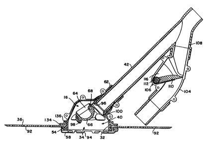
As shown in more detail in FIGS. 3-5, the intemal cleaner head 30
also comprises a pair of generally sheU-shaped housing members 48 and 50
of molded plastic or the like and adapted for interconnection by screws 52
(FIG. 5) or the like to form a generally dome-shaped and downwardly open
stn,x:ttxe defining the plenum chamber 40. In the preferred arrangement, the
housing member 48 further includes the lower foot 32 of generally annular
shape defining the downwardly open suction inlet 34 (FIG. 6) through which
water-bome debris is drawn into the plenum chamber 40. A lower margin of
the foot 32 includes a radially outwardly extending flange 54 adapted to fit
through a central opening 56 formed in the resilient disk 36. In this regard,
the disk 36 is forrned from a sufficiently resilient plastic or rubber
material so
that the opening 56 therein can be stretched sufficiently to fit over the foot
flange 54. The foot flange 54 is then seated within a ring-shaped shoe 58,
as by sliding. reception into and snap-fit retention within a generally U-
shaped dwml 60 to kx~c the shoe 58 against the underside of the disk 36
surrounding the disk opening 56 as viewed best in FIGS. 3, 4, 6 and 7. The
second housing member 50 can then be assembled with the first housing
member 48 by means of the screws 52, wherein the two housing members
48, 50 cooperatively define a radially outwardly extending lock rim 59 (FIGS.
4 and 5) spaced a short distance above the foot flange 54 to engage the
upper edge of the disk 36 bounding the disk opening 56.
The assembled housing members 48, 50 of the inner cleaner head
30 also define a cylindrical suction fitting or port 62 (FIGS. 5-8) which
forms
an outlet at an upper zone of the plenum chamber 40 opening in a direction
inclined vertically upwardly and angularly forwardly relative to the foot 32
and the suction inlet 34 defined thereby. This suction fitting 62 is coupled
in a suitable manner to a lower or upstream end of the primary suction tube
CA 02314223 2000-06-13
WO 00/23675 PCT/US99/19085
-11 -
42 which also forms a portion of the inner cleaner head 30. As shown, the
primary sucbon tube 42 extends further upwardly and forwardly at the same
angle of inclination, tenninating in an upper or downstream end for
connection by the suction fitting 20 to the vacuum hose 14.
The main control valve 16 is pivotally supported by the assembled
housing members 48, 50 within the plenum chamber 40, at a position
generally at the lower or upstream end of the primary suction tube 42. More
specifically, as shown best in FIGS. 5-8, the control valve 16 in one
preferred form comprises a valve head 64 shaped to include a part-spherical
ball-type surface segment 66 mounted onto a laterally extending shaft 68.
One end of the valve shaft 68 is supported by a bushing 70 (FIGS. 5 and 8)
on the first housing member 48, and the opposite shaft end carries a spring
key 72. This spring key 72 includes an outboard face with a pair of laterally
outwardly projecting lugs 74 adapted for seated reception within a
comesponding pair of arcuate slots 76 (FIG. 8) formed in an inboard face of
an adtustment cap 78. The aclustment cap 78 is sized to fit over a generally
cylindrical and laterally open mounting collar 80 formed on the second
housing member 50, with a side wing 82 on the cap 78 having an arcuate
track 84 therein adapted to receive a lock set screw 86 fastened into a lock
post 88. This side wing 82 can thus be accessed from the exterior of the
cleaner head and rotationally positioned and then clamped via the set screw
86 relative to the lock post 88, for variably adjusting the rotational
position
of the cap 78 and the spring key 72 supported therein relative to the
mounting collar 80 and the axis of the valve shaft 68. A biasing spring 90 of
suitable geometry is provided, such as the Illustrative coil spring with
opposite ends carried within anchor slots 91 and 93 (FIG. 8) formed
respectively In the spring key 72 and in the valve head 64 for rotatably
biasing the valve head in one direction.
The valve shaft 68 extends laterally through the plenum chamber
CA 02314223 2000-06-13
WO 00/23675 PCT/US99/19085
-12-
40 at a location to extend generally across an upper marginal edge of the
open upstream end of the primary suction tube 42, as viewed in FIG. 6. In
addition, the ball segment 66 of the valve head 64 is carried off-axis
relative
to the axis of the valve shaft 68, with the biasing spring 90 urging the valve
head 64 to swing the ball segment 66 away from the primary suction tube 42
toward the normally open position. In this normally open position, the
upstream lower end of the primary suction tube 42 is substantially open and
unobstructed for vacuum inflow of water-bome debris from the plenum
chamber 40. In this regard, the axis of the valve shaft 68 is shown to be
disposed slightly beyond a straight line flow path defined by the primary
suction tube 42. Accordingly, in the normally open position, the valve head
64 is positioned substantially to one side of an axial centerline through the
primary suction tube 42, to permit substantially unobstructed flow of water-
borne debris through said suction tube.
During operation of the pool deaner 10, water is drawn by vacuum
through the sucfion inlet 34 into the plenum chamber 40. In this regard, the
resilient disk 36 carried by the lower foot 32 normally drapes downwardly
about the shoe 58 to engage the pool surface 38 surrounding the cleaner
head. Water is drawn radially inwardly beneath the disk 36, and also drawn
downwardly through an array of perforations 92 formed in the disk 36, and
further through a series of downwardly open notches 94 (FIGS. 3, 4, 6 and
7) formed in the shoe 58 to sweep debris from the pool surface into the
plenum danber 40. The water-bome flow of debris, at negative pressure,
passes into the open upstream end of the primary suction tube 42 and
further to the vacuum hose 14 for flow to the pool filtration system (FIG. 1)
which separates and captures the debris while retuming filtered water to the
pool.
Importantly, as the water-bome debris flows from the plenum
chamber 40 into the primary suction tube 42, a pressure differential
CA 02314223 2000-06-13
WO 00/23675 PCT/US99/19085
-13-
attributable to the comparatively smaller flow area of the suction tube 42 and
resultant higher velocity water flow therein, relative to the plenum chamber
40, draws the ball segment 66 of the valve head 64 toward a substantially
closed position. More particularly, as viewed in FIG. 7, as the suction flow
entering the tube 42 reaches a critical velocity, this pressure differential
rapidly draws the ball segment 66 into close proximity with a resilient
annular
valve seat 96 mounted at the upstream end of the primary suction tube 42,
whereupon water flow into the suction tube 42 - is substantially obstructed.
In the preferred form, a stop 98 such as an adjustably set stop screw is
carried by the valve head 64 for contacting an abutment 100 within the
plenum chamber 40 to prevent complete dosure of the ball segment 66 onto
the valve seat 96, whereby there is at least some water flow to the suction
tube 42 at all times.
As the valve head 64 is abruptly halted at the substantially closed
position upon impact contact between the stop 98 and the abutment 100, the
sudden loss of momentum in combination with momentary changes in
pressure across the valve head enables the biasing spring 90 to swing the
valve head 64 rapidly in an opposite direction away from the valve seat 96,
toward the open position. This opening movement is accompanied by
resumed substantially unobstructed flow of water and debris to the primary
suction tube 42 for a brief interval, followed by vacuum-drawn swinging
movement of the valve head back toward the substantially closed position.
Return closure motion of the valve head 64 is typically assisted by the coil
biasing spring 90 which, upon opening movement of the valve head 64 past
a static at-rest open position, partially winds the spring 90 in an opposite
direction to apply an initiat spring force urging the valve head 64 to move
back toward the valve seat 96. Accordingly, the valve head 64 is driven in
a-cyclic or oscillatory fashion, between the open and substantially dosed
positions. This results in a rapid succession of pressure fluctuations or
CA 02314223 2000-06-13
WO 00/23675 PCT/US99/19085
-14-
pulsations within the cleaner head, to induce a water hammer effect acting
in the direction of the water flow, namely, upwardly and forwardly generally
along the axis of the primary suction tube 42. These pulsations effectively
drive or transport the deaner head in a generally fonNard direction within the
swimming pool, in a series of small incremental hop-like steps to traverse
submerged pool surfaoes to vacuum debris settled thereon. As the cleaner
is driven fonivardly in this manner, water-bome debris is swept from the
pool surface 38 and through the primary suction tube 42, with minimal risk
of clogging or fouling the interface between the valve head 64 and the
annular valve seat 96. That is, in the open position, the valve head 64 is
substantially out of alignment with the flow to and through the primary
suction tube 42. In the substantially dosed position, at least some continued
flow is permitted.through the spa e between the valve head 64 and the valve
seat 96 to avoid capture of debris and potential interruption of reciprocatory
valve head movement. In this regard, such risk of clogging is further
reduced by forming the valve seat 96 from a resilient material having a
relatively thin or sharp leading edge as shown, adapted to undergo some
flexing in response to these pressure fluctuations as the valve head 64
moves to and from the substantially closed position. Moreover, the use of
the resilient valve seat 96 substantially without direct physical or impact
contact with the valve head 64 effectively prevents wear of the valve seat
and valve head thereby serving to prolong the service life of the pool
cleaner.
The spedfic operating characteristics of the pool cleaner are
dependent upon a variety of factors, including the vacuum pressure applied
via the vacuum hose 14. In addition, the cyclic rate of the valve head
movement can be adusted by variably setting the force applied to the valve
head 64 by the biasing spring 90. In this regard, the arcuate track 84 in the
side wing 82 of the adjustment cap 78 permits rotatable adjustment of the
CA 02314223 2000-06-13
WO 00/23675 PCT/US99/19085
-15-
torsion type biasing spring 90, for selectively increasing or decreasing the
applied biasing force as desired. Moreover, in accordance with one further
aspect of the invention, the laterally presented base of the adjustment cap
78 may be perforated to include small apertures 102 (FIG. 5), to
accommodate a low circulatory water flow therethrough. This low rate
circulation of water through the adjustment cap 78 has been found effective
to reduce or eliminate accumulation of fine grit therein, wherein such grit
accurnuiation could otherwise interfere proper operation of the biasing spring
90.
As shown in FIGS. 5-7 and 9, the cleaner head 30 may optionally
and additionally include a bypass suction tube 104 having a bypass valve
106 mounted therein for coordinated operation with the main control valve
16. More specifically, the primary suction tube 42 may be formed to include
a Y shaped junction 108 near the upper end thereof for removable mounting
of the bypass suction tube 104 which, when employed, extends downwardly
therefrom generally in parallel relation beneath the primary tube 42. The
bypass suction tube 104 terminates in a lower end spaced a short distance
above the resilient disk 36, at a location forward from the foot 32 and
related
suction inlet 34. This lower end of the bypass suction tube defines a
secondary or bypass inlet designed for vacuum-drawn inflow of water and
relatively large debris which can tend to collect on the upper face of the
disk
36 as the deaner head moves forwardly within the swimming pool.
The bypass valve 106 is mounted within the bypass suction tube
104, and is adapted for cydic movement between a normally closed position
and a pressure. responsive open position in coordination with the cyclic
operation of the main control valve 16. In one preferred form as shown in
FIGS. 6, 7 and 9, the bypass valve 106 comprises a valve flap 110
protruding from a sleeve base 112 carried on a shaft 114 extending laterally
across a pocket 116 formed along the length of the bypass tube 104. In this
CA 02314223 2000-06-13
WO 00/23675 PCT/US99/19085
-16-
regard, the illustrative bypass tube is formed by intenconneccted
longitudinally
mated tube halves, with one end of the valve shaft 114 carried by a bushing
118 on one tube half and the opposite shaft end carried by an adjustment
hub 120. The adjustment hub 120 is seated within an open port 122 in a
friction collar 124 fastened onto the opposite tube half by screws 126 or the
like. A biasing spring 128 of suitable configuration is provided, such as the
illustrative coil spring with its opposite ends seated within slots 127 and
129
(FIG. 9) forrned respectively wkhin the adjustment hub 120 and an outboard
face of the sleeve base 112, so that the torsion-type spring 128 applies a
selected biasing force urging the valve flap 110 toward a normal position
extending across and closing the bypass suction tube 104 (FIG. 6). The
specific magnitude of this biasing force may be adjustably selected by
rotatably positioning the adjustment hub 120 within the friction collar 124,
by
means of an exposed adjustment slot 130 on an outboard face of the hub
120.
During operation, with the bypass sucfion tube 104 and the related
bypass valve 106, the normally open main control valve 16 is pivotally
displaced between the open and substantially closed positions to induce
pressure fluctuations or pulsations for forwardly driving the pool cleaner in
incremental steps, as previously described. When the main valve 16 is
drawn to the substantially dosed position, the vacuum within the primary
suction tube 42 momentarily increases to a level sufficient to draw the
bypass valve 106 from the nomially closed position to the open position, as
viewed in FIG. 7. That is, the increased vacuum, or decreased pressure
level, along the primary suction tube 42 causes the bypass valve flap 110 to
swing upwardly in the downstream-flow direction to the open position to
permit water flow upwardly through the bypass tube 104 and further through
the vacuum hose 14 to the pool filtration system 12. This timed opening of
the bypass suction tube 104, and the accompanying surge flow of water
CA 02314223 2000-06-13
WO 00/23675 PCT/US99/19085
-17-
therethrough, effectively enhances the forward step wise transport of the
pool cleaner during operation. When the main valve 16 retums to the open
position, the vacuum level in the primary suction tube 42 is partially
relieved
to permit the biasing spring 128 to return the bypass valve flap 110 to the
closed position. Accordingly, with this construction, the bypass valve 106 is
cyclically opened and dosed in opposition to or out of phase with the main
control valve 16, whereby the cleaner is effectively driven forwardly in
incremental steps yet water flow through the cleaner head to the vacuum
hose 14 is substantially continuous by altemate flow through the primary and
bypass suction tubes 42 and 104.
The forward motion of the pool cleaner 10 desirably follows a
nonlinear path to achieve random travel throughout the swimming pool, so
that the cleaner will pick up settled debris from substantially all submerged
surfaces of the pool within a relatively short period of time. To achieve this
nonlinear motion, the pattem of perforations 92 formed in the resilient disk
36 is formed in an asymmetric pattem as shown best in FIG. 5 with more
open hole area at one lateral side of the central disk opening 56 than at the
other. With this configuration, the side of the disk associated with the
smaller open hole area is retained by the vacuum flow through the suction
inlet 34 with a greater force, resulting in increased friction between the
disk
36 and the underlying pool surface 38 as the cleaner moves forwardly in
small steps. This nonunifonn frictional resistance between the disk and the
pool surface causes the cleaner to tum slightly upon each fonnrard step,
wheneby the deaner moves forwardly with a slight tuming motion. Within a
swimming pool having variable depth and curved transition regions between
the floor and side walls, the result is an enhanced overall randomness of
travel.
The nonlinear forward motion of the cleaner may be further
enhanced by providing a nonperforate apron 132 (FIG. 5) overlying a
CA 02314223 2000-06-13
WO 00/23675 PCT/US99/19085
-18-
selected arcuate segment of the resilient disk 36 at one lateral side of the
cleaner head 30. As shown, this apron 132 may indude a mounting ring 134
at one side thereof for assembly about the housing members 48, 50 of the
cleaner head, at a location sandwiched between the upper side of the disk
36 and the upper lock rim 59. In this regard, the lock rim 59 formed
cooperatively by the two housing members 48, 50 conveniently includes a
pair of gaps at the frorit and rear for seated reception of upstanding ears
136
(FIGS. 4-7) on the mounting ring 134 to insure nonrotational mounting and
correct rotational alignment of the apron 132 relative to the cleaner head.
From the mounting ring 134, the apron 132 comprises a part-circular arcuate
and flexible rubber or plastic sheet segment extending radially outwardly
from one side of the cleaner head 30, to overlie and close the perforations
92 formed therebelow in the resilient disk 36. Closure of these perforations
incxeases the frictional resistance between the disk 36 and the pool surface
38 at that side of the cleaner head, to contribute further to forward cleaner
travel with a nonlinear tuming motion. Moreover, if desired, the nonlinear
path of travel and overall random travel characteristics may be further
enhanced by sizing the central opening 56 in the disk 36 to permit rotation
of the disk with its asymmetric pattem of perforations 92 about the cleaner
head 30, such that the asymmetric forces causing the cleaner to turn will
also cause the disk 36 to roate slightly upon each incremental forward step.
The result is that the frictional resistance between the pool surface and the
disk portion underlying the apron 132 varies according to the rotational
position of the disk, whereby the curvature of the nonlinear forward path is
not constant.
In acoordanoe with.a further aspect of the invention, the geometry
of the housing members 48, 50 conveniently permits partial disassembly to
access ft main control valve 16, without requiring disassembly of the disk
56. More particularly, as depicted best in FIG. 5, by forming the annular
CA 02314223 2000-06-13
WO 00/23675 PCT/US99/19085
-19-
lower foot 32 and ft refated foot flange 54 on the first housing member 48,
together with a portion of the upper lock rim 59, the second housing member
50 can be disassembled to pernnit access to the plenum chamber 40 and the
control valve 16 therein in the event that service or maintenance is required.
Such removal of the second housing member 50 may be performed without
removing the resilient disk 36 or the related overlying apron 132.
Alternatively, if desired, the housing members 48; 50 may be constructed as
a one-piece component, with service access to the control valve 16 being
perrnitted through the laterally open mounting collar 80 upon removal of the
cap 78.
Moreover, in the event that the cleaner 10 attempts to pick up
debris sufficiently large to obstruct the entire suction inlet 34 at the foot
of
the cleaner head 30, auxiliary inflow ports are provided to insure at lest
some sustained water flow through the cteaner in order to prevent undesired
cavitation bun-out of the filtration pump 18. Such auxiliary inflow ports 138
are formed in the housing members 48, 50 (FIGS. 2 and 5), and additional
auxiliary Inflow ports 140 are formed in the outer housing 28 (FIGS. I and
2).
The improved suction powered pool cleaner of the present
invention thus provides a ball-type main control valve 16 mounted for cyclic
movement to induce pressure fluctuations or pulsations for driving the
cleaner forwardly in a succession of incremental steps, with the ball-type
valve moving to an open position acx~mmodating substantially unobstructed
flow of water-bome debris in a manner which is resistant to clogging.
Moreover, the additional bypass suction tube 104 and related bypass valve
106 provide an additional flow path positioned especially for suctioning large
debris. The resilient disk 56 provides asymmetric frictional forces causing
the pool cleaner to advance along a nonlinear path for improved
randomness of travel.
CA 02314223 2000-06-13
WO 00123675 PCT/US99/19085
-20-
A variety of further modifications and improvements in and to the
suction powered pool cleaner of the present invention will be apparent to
those persons skilled in the art. For example, the decorative extemal
housing 28 could be omltted and the functional components thereof
including the nose wheel 46 and the carrying handle 44 could be provided
as a portion of the exterior geometry of the cleaner head 30. Moreover,
while a ball-type valve head 64 is shown and described to form the main
control valve 16, it vaill be understood and appreciated that altemative valve
head configurations may be employed. Further, while the optional bypass
valve 106 is shown in the form of a spring-loaded valve flap 110, altemative
bypass valve geometries may be used such as a resilient diaphragm valve
of the type shown and described in U.S. Patent 5,634,229. Accordingly, no
limitation is intended by way of the foregoing description and accompanying
drawings, except as set forth in the appended claims.