Note: Descriptions are shown in the official language in which they were submitted.
CA 02314344 2000-06-09
WO 99/36367 PC'T/KR99/00013
1
COOLER OF OPTICAL .FIBER DRAW TOWER
Technical Field
The present invention relates to an optical fiber draw tower, and more
particularly, to a ~;,ooler of an optical fiber draw tower, capable of fast
cooling
optical fiber melted in a melting furnace and then drawn in a predetermined
diameter before coating is applied.
Background Art
In general, optical fibers are obtained by drawing a preform for optical
fibers using an optical fiber draw tower. FIG. 1 is a schematic view of a
general
optical fiber draw tower. The optical fiber draw tower comprises a melting
furnace
12 for melting a prefortn 10 at a high temperature to draw out uncoated
optical
fiber 14, a diameter measuring unit 16 installed below the melting furnace 12,
for
continuously measuring the outer diameter of the uncoated optical fiber to
uniformly control the outer diameter of the uncoated optical fiber, a cooling
unit
18 below the diameter measuring unit 16, for cooling down the temperature of
the
uncoated optical fiber 14 to room temperature, a coating unit 20 below the
cooling
unit 18, for coating the surface of the uncoated optical fiber with UV-curable
resin
such as acryl resin or silicon resin so as to protect the uncoated optical
fiber 14
from the elements of nature, a curing unit 22 below the coating unit 20, for
curing
the coated optical fiber 24, a capstan 26 below the curing unit 22, for
drawing out
an optical fiber from the preform 10 in a lower direction, and a spool 28 next
to
the capstan 26, for winding the drawn optical fiber.
ZS A method for preparing (drawing) an optical fiber coated with the UV-
curable resin will be described. The preform 10 is slowly provided into the
melting
furnace 12 according to the position control mechanism of a preform position
controller (not shown). Here, the preform 10 is heated in the melting furnace
12
to several thousands of centigrades, typically, to 2,100-2,200°C. As a
result, the
uncoated optical fiber 14 is drawn from the preform 10. Here, drawing force
originates from the capstan 26 and is applied to the uncoated optical fiber
14.
Then, the diameter measuring unit 16 measures the outer diameter of the
uncoated
CA 02314344 2000-06-09
WO 99/36367 PCT/KR99/00013
2
optical fiber 14 drawn to determine whether the diameter is equal to a
predetermined diameter, e.g., 125~m, and sends the measured diameter values to
a diameter controller (not shown). The diameter controller controls the
rotating
speed of the capstan 26 such that the diameter of the uncoated optical fiber
14 is
maintained at 125~.m. Then, the capstan 26 rotates to control the drawing
force on
the uncoated optical fiber 14 in response to the control of the diameter
controller,
thereby drawing out the uncoated optical fiber 14 in a lower direction.
Then, in order to protect the uncoated optical fiber 14 cooled at high speed
by the cooling unit 18, the coating unit 20 coats the surface of the falling
down
uncoated optical fiber 14 with a UV-curable resin, e.g, acryl resin or silicon
resin.
Then, the optical fiber 24 coated with the UV-curable resin is cured by the
curing
unit 22, and is then wound around the spool 26 under the control of drawing
force
of the capstan 26.
Also, as the preform becomes large, the optical fiber draw tower must be
1 S increased. This is because very rapid drawing is necessary as the preform
becomes
large. After the preform is melted passing through a melting furnace and then
drawn out, the drawn optical fiber is subjected to coating. Here, prior to
coating
of the optical fiber" the temperature of the uncoated optical fiber must be
lowered
to a predetermined temperature. In general, the temperature of the uncoated
optical
fiber right drawn from the melting furnace is 2,000°C or more. However,
in order
to guarantee stable coating on the drawn optical fiber, the temperature of the
uncoated optical fiber must be cooled to at least 40°C or less (usually
to room
temperature). For. this purpose, the temperature of the uncoated optical fiber
is
cooled rapidly using a cooler. However, the cooler in use is not sufficient to
cool
the uncoated optical fiber to keep pace with the rapid drawing speed. FIG. 2
shows a general cooler adopted by the optical fiber draw tower shown in FIG.
1.
In the cooler having a pipe shape, the drawn optical fiber is cooled by
filling the
pipe with helium (He).
Thus, it is necessary to increase the height of the optical fiber draw tower
in order to quickly ~;,ool the uncoated optical fiber in response to the rapid
drawing
speed of the optical fiber. However, making the optical fiber draw tower high
increases the manufacturing cost and it is not efficient.
CA 02314344 2000-06-09
WO 99/36367 PCT/KR99/00013
3
Disclosure of the Invention
To solve the above problems, it is an object of the present invention to
provide a cooler of an optical fiber draw tower, capable of rapidly cooling an
optical fiber which is melted in a melting furnace and then drawn, without
increasing the height of a conventional optical fiber draw tower, such that
the
optical fiber can be rapidly drawn out from a preform.
According 1:o an aspect of the object of the present invention, there is
provided a cooler of an optical fiber draw tower, situated below a melting
furnace
for melting a preforrn for an optical fiber, for cooling the optical fiber
drawn from
the preform melted in the melting furnace, wherein the cooler comprises at
least
one heat exchanger installed with a predetermined length surrounding the
optical
fiber drawn from the melting furnace, for cooling the drawn optical fiber.
Preferably, the heat exchanger is formed of a thermo-electric cooler (TEC)
for taking electrical energy through one heat absorbing surface to emit heat
to the
other heat emitting surface and has a tubular shape in which the heat
absorbing
surface of the TEC surrounds the optical fiber drawn from the melting furnace
along the drawing direction by a predetermined length, and the drawn optical
fiber
is cooled as it passes through the tubular TEC.
Preferably, the cooler further comprises an auxiliary cooler attached to the
heat emitting surface of the TEC, for cooling the emitted heat, and the
auxiliary
cooler is installed contacting the heat exchanger and comprises a tank in
which is
a heat exchange medium flow path is arranged, a supply pipe attached to the
tank
to supply a heat exchange medium through the l~at exchange medium flowing
path,
and an exhaust pipe for exhausting the heat exchange medium.
According to another aspect of the object, there is provided a cooler of an
optical fiber draw tower, situated below a melting furnace for melting a
preform
for an optical fiber, for cooling the optical fiber drawn from the preform
melted in
the melting furnace, wherein the cooler has a shape having two openings
through
which the drawn optical fiber passes in the vertical direction, and comprises
two
thermo-electric coolers (TECs) each having one heat absorbing surface for
taking
electrical energy and the other heat emitting surface for emitting heat,
arranged
CA 02314344 2000-06-09
W4 99/36367 PCT/KR99/00013
4
such that two heat absorbing surfaces face each other, surrounding the drawn
optical fiber, and two spacers interposed between the TECs to surround the
drawn
optical fiber.
Preferably, the cooler further comprises an auxiliary cooler attached to each
heat emitting surface of the facing TECs. Also, at least two coolers may be
arranged in the optical fiber drawing direction. Preferably, each cooler
further
comprises an auxiliary cooler attached to each heat emitting surface of the
facing
TECs, and an insulating material is interposed between the coolers.
Brief Descr~tion of the Drawings_
FIG. 1 is a schematic view of a general optical fiber draw tower;
FIG. 2 shows a general cooler adopted in the optical fiber draw tower
shown in FIG. 1;
FIG. 3 shows a cooler of an optical power draw tower according to a
preferred embodiment of the present invention, which adopts a thermo-electric
cooler (TEC) and doubles the cooling effect;
FIG. 4 is a top view of the cooler shown in FIG. 3;
FIG. 5 shows the structure of an example of the TEC;
FIG. 6 shows positions a, b and c at which temperatures are measured to
illustrate the cooling effect according to distance from the preform;
FIG. 7 is a plot showing the temperature of the optical fiber at the position
b of FIG. 6 according to drawing speed;
FIG. 8 is a plot showing the temperature of the optical fiber at the position
c of FIG. 6 according the drawing speed; and
FIG. 9 is a plot illustrating change in temperature of the optical fiber
according to the period of time t which is required for the preform of the
position
a to be drawn as an optical fiber to reach the position c.
Best mode for cart~rin out the Invention
A Peltier effect refers to the change in temperature when current flows
across two different materials contacting each other. A small solid state
device,
such as a heat pump, based on the Peltier effect, is called a "thermo-electric
cooler
CA 02314344 2000-06-09
WO 99/36367 PCT/KR99/00013
(TEC)". FIG. 5 shows an example of the TEC, in which p-type and n-type
semiconductor pairs are arranged in series between two ceramic plates.
The basic idea of the present invention is to construct a cooler used in a
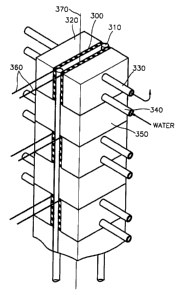
optical fiber draw tower using the TEC. FIG. 3 shows a cooler of an optical
fiber
5 draw tower according to the present invention, which adopts the TEC to
double the
cooling effect. The basic module includes two TECs 300, two rods 310, and an
auxiliary cooler consisting of three units 320, 330 and 340 which is attached
to
each heat-emitting surface of the TECs 300. FIG. 4 is a top view of the cooler
shown in FIG. 3. The cooler shown in FIG. 3 is constituted of two or more
basic
modules connected to each other, and an insulating material 350 interposed
between
the basic modules. :Here, the height of the cooler can be controlled by the
number
of basic modules adopted.
The TEC 31x? is a heat exchanger for generating heat by taking electrical
energy through power supply lines 360. The TEC is installed to surround the
optical fiber drawn from the melting furnace 12 of FIG. 1. That is, the TECs
300
are arranged so that their heat absorbing surfaces face each other around the
optical
fiber drawn from the melting furnace 12. Also, fins may be attached so as to
enhance the cooling effect at the heat absorbing surfaces of the TECs 300.
Also, the rods 310 act as a spacer for separating the facing TECs 300 by a
predetermined interval.
An optical fiber 370 passes through the space enclosed by two TECs 300
and two rods 310 in the vertical direction, and a coolant is supplied to the
space to
fiirther lower the temperature of the optical fiber 370. The coolant may be
helium
(He), argon (Ar) or nitrogen (N). In this embodiment, He or Ar is used as the
coolant.
Here, the three units constituting the auxiliary cooler which adopts a water
cooling system are a tank 320 in which a heat exchange medium flowing path is
formed, a supply pipe 340 attached to the tank 320, for supplying the heat
exchange
medium through the heat exchange medium flowing path to the tank 320, and an
exhaust pipe 330 for exhausting the heat exchange medium. In this embodiment,
water is used as the: heat exchange medium. However, any medium capable of
exchanging heat, e.g. , oil, may be used in some cases. Also, fins may be
attached
CA 02314344 2000-06-09
WO 99/36367 PCT/KR99/00013
6
to the tank 320 to enhance its cooling effect. An auxiliary cooler adopting an
air
cooling system, in which air is supplied using a fan for cooling, may be used.
That
is, the cooling system adopted by the auxiliary cooler is not limited to the
above
embodiment according to the present invention.
The insulating material 350 blocks the heat transfer from an upper basic
module to a lower basic module, thereby enhancing the cooling efficiency of
each
basic module of the cooler. The insulating material 350 used in this
embodiment
is styrofoam. However, the insulating material is not limited to a specific
material.
The cooler illustrated in this embodiment has a hexahedral shape, and the
uncoated optical fiber 370 drawn from a melting furnace is surrounded using
two
TECs 300 and two rods 310. Preferably, two TECs are used in place of the two
rods 310. More preferably, the cooler is formed using a tubular TEC. That is,
the
cooler can be modified into various shapes without limitations. Also, the
number
of basic modules adopted by the cooler may be different. That is, in the case
where the length of the TE(: is sufficient to cool the uncoated optical fiber
drawn
from the melting furnace keeping pace with the drawing speed, the cooler may
be
constituted of only one basic module.
FIG. 6 shows positions a, b and c at which temperatures are measured to
illustrate the cooling effect according to distance from the preform.
Reference
character a indicates the bottom line of the preform, and reference characters
b and
c indicate the positions separated from the bottom line a by 100cm and 200cm,
respectively. Here, the cooler is located between the positions b and c. Also,
T
s
indicates the temperature of the preform, and Tl and T2 indicate the
temperatures
of the drawn optical fiber at the positions b and c, respectively.
FIG. 7 is a plot showing the temperature T~ of the drawn optical fiber at
the position b of FIG. 6 according a drawing speed Vf. FIG. 8 is a plot
showing
the temperature T2 of the drawn optical fiber at the position c of FIG. 6
according
the drawing speed 'Vf.
FIG. 9 is a plot illustrating the change in temperature (log(T~-T2)) of the
optical fiber according to the time t required for the preform of the position
a to
be drawn as an optical fiber to reach the position c. Here, the time t is
calculated
by ~, wherein L, the distance between the positions b and c, is 200cm. In the
CA 02314344 2000-06-09
W4 99/36367 PCT/KR99/00013
7
legend of FIG. 9, "He9", "He6", "He3" and "Hel.S" indicate the cases when He
as a coolant flows through the cooler at a flowing rate of 9, 6, 3 and 1. S
liters per
minute, respectively, while the cooler adopting only the TEC operates. "Air"
indicates the case where the cooler is not operated and no coolant is
provided,
"ONLY He3" indicates the case where only He is supplied at a flowing rate of 9
liters per minute while the operation of the cooler is stopped, and "Ar3"
indicates
the case where Ar is suppli~l as the coolant at a flowing rate of 3 liters per
minute
while the cooler is operated.
Industrial A_Rnlicabil~
As described above, the cooler of an optical fiber draw tower according to
the present invention can enhance the cooling effect. Thus, the optical fiber
drawing speed can be increased without increasing the height of the optical
fiber
draw tower.