Note: Descriptions are shown in the official language in which they were submitted.
CA 02314448 2000-07-21
GRAFT FIXATION DEVICE AND METHOD
Technical Field
The field of art to which this invention relates is
surgical fastening devices, in particular, surgical
fastening devices for fixating tissue grafts to bone.
Background of the Invention
The medical technology associated with tissue
engineering has advanced at a rapid pace. In particular,
it is now known to harvest cells from the human body, for
example, chondrocytes and fibrochrondrocytes from the
knee joint. These autologous cells are then cultured in
a laboratory environment on a bioabsorbable matrix. The
matrix will t;ypically have a shape substantially similar
to the tissue section which needs to be replaced. After a
sufficient period of time in an appropriate culture
medium at the proper environmental conditions, the
harvested cel:ls will grow on the matrix to form an
implantable section of tissue having substantially the
same physical configuration as the section of tissue
which needs to be replaced in the patient. Such a
tissue-engineered construct consisting of cells on the
matrix (or, alternatively, consisting of a matrix alone
without cells) is then affixed to the bone site using
CA 02314448 2000-07-21
2 -
conventionally known surgical fasteners including
sutures, periosteal coverings, or fibrin glue.
The advantages of tissue engineering are many, not
the least of which is, for example, that it is now
possible to replace cartilage with living cartilage
tissue. In addition, the likelihood of rejection of the
tissue implant is minimized since the cartilage tissue
which has been. grown in-vitro is identical to the
autologous cartilage of the patient.
Although existing matrix fixation devices are
adequate for their intended use, there are also some
disadvantages attendant with their use. First of all
these fixation devices are generic in the sense that they
are not specifically designed for matrix fixation to bone
or soft tissue, but can be used for a variety of surgical
procedures. Other disadvantages include the difficulty
in using many of these devices in a minimally invasive
arthroscopic procedure. Additiona]. disadvantages include
the difficulty and surgical challenge of harvesting a
piece of periosteum for use as a periosteal flap, the
significant patient morbidity associated with such
harvesting, and the difficulty in suturing such a thin,
compliant material to surrounding tissue.
Accordingly, there is a need in this art for novel
fixation devices that will effectively affix a matrix of
CA 02314448 2000-07-21
- 3 -
tissue-engineered tissue to a bone or other anchoring
site so that the tissue may continue to grow and
regenerate in the patient's body.
Disclosure of the Invention
Therefore, it is an object of the present invention
to provide a fixation device that effectively fixates a
tissue-engineered matrix to a bone or other anchoring
site, thereby enabling the implanted matrix to remain in
place while the tissue continues to grow and regenerate.
It is a further object of the present invention to
provide such ,a device for fixating a matrix to a bone
site which is easily installed using an arthroscopic
procedure or an open procedure.
it is yet a further object of the present invention
to provide such a device for fixating a matrix to a bone
site which does not require sutures or suture knot tying.
It is still yet a further object of the present
invention to provide a surgical method for fixating a
matrix utilizing such a device in a location within a
patient's body.
Accordingly, a graft fixation device is disclosed.
The graft fixation device has first and second
CA 02314448 2000-07-21
- 4 -
implantation members. The members are elongated and
preferably have a cylindrical configuration. The members
also have distal ends, proximal ends, and longitudinal
axes. There are longitudinal passages extending through
the entire length of each implantation member. The
members have outer surfaces. The implantation members
are connected to each other by a rod member having first
and second ends and a central section. The first end of
the rod member extends from the proximal end of the first
implantation member and the second end of the rod member
extends from the proximal end of ttie second implantation
member. The rod member is preferably relatively rigid
and may be configured to have geometric shape, for
example, an inverted "U" shape. However, the rod member
may also be flexible. The rod member maintains the
implantation members at a relatively fixed distance from
each other. The central section of the rod member is
designed to engage a section of a tissue-engineered
matrix implant. In a preferred embodiment, the
implantation members have a series of ridges extending
out from the outer surfaces of the implantation members
to assist in preventing withdrawal from a bone site or
other anchoring site after the implantation members are
implanted into previously-created bore holes.
Yet another aspect of the present invention is a
method of using the graft fixation device of the present
CA 02314448 2000-07-21
- 5 -
invention to affix a matrix containing tissue-engineered
tissue to a bone.
These and other features and advantages of the
present invent:ion will become more apparent from the
following description and accompanying drawings.
Brief Description of the Drawings
FIG. 1 is a perspective view of a graft fixation
device of the present invention.
FIG. 2 is a cross-sectional view of the graft
fixation devic:e of FIG. 1 taken along view line 2-2.
FIGS. 3-6) illustrate a surgical procedure for
affixing a matrix to bone using the graft fixation device
of the present: invention.
FIG. 7 is an illustration of a graft fixation device
of the present invention after the implantation members
have been implanted in bore holes in bone illustrating
the device affixing a matrix securely to the surface of a
bone.
FIG. 8 is a cross-sectional view of the graft
fixation devic:e of FIG. 7 implanted in bone, and taken
along View Line 8-8.
CA 02314448 2000-07-21
- 6 -
FIG. 9 is an alternative embodiment of a graft
fixation device of the present invention having two
connecting members.
FIG. 10 is a perspective view of an instrument
useful for making bore holes in bone into which the
implantable members of the graft fixation devices of the
present invention may be emplaced.
FIG. 11 is a perspective view of an instrument
useful for implanting the device of the present invention
into bore holes made in bone.
FIG. 12 is a view of a tissue engineered matrix
secured to a bone with several graft fixation devices of
the present invention.
Description of the Preferred Embodiments
The graft fixation devices of the present invention
can be made from conventional bio-compatible materials,
including absorbable and non-absorbable materials, as
well as biodegradable materials. The non-absorbable
materials which can be utilized include conventional
biocompatible materials such as stainless steel,
polyethylene, Teflon, Nitinol, non-absorbable polymers,
other bio-compatible metals, ceramics, combinations
CA 02314448 2000-07-21
- 7 -
thereof and the like. The absorbable materials which can
be used to mariufacture the graft fixation devices of the
present invention will typically include those
conventional bioabsorbable or bioresorbable materials
known in this art which can be effectively molded or
machined. The bio-absorbable and bio-resorbable
materials include polylactic acid, polydioxanone,
polycaprolactone, polyglycolic acid, polygalactic acid,
other known biocompatible bioabsorbable and bioresorbable
polymers, ceramics, composites, combinations thereof and
the like and equivalents thereof.
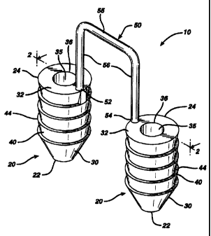
Referrinq now to FIGS. 1-2, a preferred embodiment
of a graft fixation device 10 of the present invention is
illustrated. The graft fixation device 10 is seen to
have implantation members 20. The implantation members
are seen tc> be elongated members, preferably having a
substantially cylindrical shape. 'Phe members 20 may have
other geometric shapes including conical, pyramidal,
20 polygonal, cubic, spherical, etc. The implantation
members 20 are seen to have distal ends 22 and proximal
ends 24. Each implantation member 20 is seen to have an
outer surface 28 and a longitudinal axis 29. Each member
20 is also seen to have longitudinal passage 35 extending
therethrough. The implantation members 20 are also seen
to have optiorial frustoconical ends 30, and proximal
endface surfaces 32. Although it is preferred that
endface surfaces 32 be flat, endface surface 32 may also
CA 02314448 2000-07-21
- 8 -
be angled, concave, convex, etc. Endface surface 32 is
seen to have central circular opening 36 in communication
with passage 35. Preferably, central opening 36 will have
a circular cross-section, but it may have other geometric
cross-sections as well including elliptical, polygonal,
square, rectangular, combinations thereof and the like.
Members 20 are also seen to have distal end face surfaces
37 having circular openings 38 in communication with
passages 35. As shown with the optional frustoconical end
30, the annular end face surface 37 is of de minimis
thickness around opening 38, however this thickness would
increase in the absence of a frustoconical end. Also
seen to extend out from the surface 28 of member 20 are a
series of opt.ional projections 40 having tissue
engagement edges 44. Without the projections 40, the
surface 28 of the member 20 will be smooth.
The device 10 is seen to have graft retention member
50 connecting the implantation members 20. Retention
member 50 is seen to be a rod-like member having first
end 52, second end 54 and central section 55. First end
52 is seen to extend from proximal. endface surface 32 of
the first member 20 while end 54 is seen to extend up
from the proximal endface surface 32 of the other member
20. The ends 54 and 52 of retention member 50 may also
if desired extend from or be mounted to any section of
outer surface 28. The connecting member 50 is seen to be
preferably bent or shaped into three segments including
CA 02314448 2000-07-21
- 9 -
top segment 55 and leg segments 56. The top segment 55
is seen to be substantially perpendicular to the leg
segments 56. Although it is preferred that connecting
member 50 have an inverted "U" configuration, the
connecting member 50 may have other geometric
configurations including semicircular, arced, curved,
triangular, polygonal, U-shaped, and the like and
combinations thereof. The ends 52 and 54 of connecting
member 50 may be permanently affixed to the implantation
members 20, or may be removably attached thereto in a
conventional manner. Member 50 may be rigid or flexible.
Member 50 will have a sufficient surface area to
effectively retain a tissue-engineered matrix in place on
a bone or other body surface. Preferably, connecting
member 50 wi1:L have a circular cross-section, but may
have other geometric cross-sections as well including
elliptical, polygonal, square, rectangular, combinations
thereof and the like. Member 50 may be rigid or
flexible, and may have a single filamentary structure or
have multiple interconnected filaments or members.
Referrinq now to FIGS. 3-8, the use of the graft
fixation devices 10 of the present invention in a
surgical procedure is illustrated. Referring first to
FIG. 3, the ir.iitial step, prior to the installation of a
matrix containing a tissue-engineered tissue using a
graft fixation device 10 of the present invention, is to
drill or "tap" two bore holes 200 into a bone 210, for
CA 02314448 2000-07-21
- 10 -
example, subc:hondral bone in the knee joint. The bore
holes 200 are seen to be cylindrical holes having a
bottom 208 and an open top 202 and side walls 205.
Optionally, the bore holes may be bone tunnels with a
continuous passage and no bottom, or an open bottom. It
is particularly preferred to tap the holes in the bone by
using an instrument 400 as illustrated in FIG. 10 which
has a proxima.l section conventionally referred to in this
art as a"slap hammer" section. The term "tapping" or
"tap" as used herein is defined to mean a procedure
wherein the distal pointed prongs 420 extending from the
distal end 415 of the shaft 405 of instrument 400 are
located over a bone site, and the proximal end 410 of
instrument 400 is tapped or hit with slidable hammer
handle 450 (of the "slap hammer"), which slides on shaft
460 between proximal end 410 and proximal stop 470, to
form the bone bore holes 200. The distal end 465 of
shaft 460 is connected to proximal end 411. Proximal
stop 470 is mounted to proximal end 467. Hammer handle
450 is seen to have grasping section 451, collars 455 and
longitudinal passage 457. Those skilled in the art will
appreciate that a similar pointed instrument may be used
to "tap" in the bore holes into bone, that is, any
instrument having a nail-like distal end. In addition,
although not preferred, one bone bore hole at a time may
be "tapped" in. If the surgeon decides to drill the bore
holes into bone, any conventional surgical drilling
apparatus may be used. After the bore holes 200 are
CA 02314448 2000-07-21
- 11 -
formed into the bone 210, the matrix 220 containing
tissue-engineering tissue is placed upon the bone surface
201 by the surgeon as seen in FIG. 4. Next, the graft
fixation device 10 is mounted on to the insertion
instrument 250. Insertion instrument 250, as illustrated
in FIG. 11, is seen to be an elongated rod 260 having a
proximal end 262 and a distal end 264. Mounted to the
distal end 264 of the rod 260 is the depth stop 290. The
depth stop 290 is seen to be a substantially rectangular
member which :i.s mounted perpendicular to the longitudinal
axis 251 of the rod 260. Depth stop 290 is seen to have
bottom 292. Extending distally from the bottom 292 of
plate member 290 is a pair of parallel, spaced-apart,
mounting prongs 270. The mounting prongs 270 are seen to
be substantially rod-like members having distal pointed
tips 277 and proximal ends 272. The prongs 270 are seen
to have first section 273 and distal section 275.
Section 273 is seen to have a greater cross-sectional
dimension thari distal section 275 such that the entire
section 275 is insertable into passages 35 of members 20,
while proximal. section 273 is not insertable therein.
Instrument 250 is also seen to have a "slap hammer
section" consisting of proximal shaft 300 extending from
proximal end 262, slidable hammer handle 320 (the "slap
hammer") which is slidable upon shaft 300 between
proximal end 262, and proximal stop 330. Hammer handle
member 320 is seen to have grasping section 325, end
collars 327 and longitudinal passage 329. The graft
CA 02314448 2000-07-21
_ 12 -
fixation device 10 is mounted to the insertion instrument
250 by sliding the implantation members 20 onto the
prongs 270 such that the distal sections 275 of members
270 are engaged within the longitudinal passages 35 of
members 20 anci distal points 277 p:rotrude beyond the end
of distal endface surfaces 37. Then, as seen in
FIGS. 5 and 6, the instrument 250 is manipulated such
that the graft: fixation device 10 is inserted through
matrix 220 anci into bone 210 by moving the implantation
members 20 mounted on prongs 270 into the bore holes 200
such that the members 20 are engaged in the bore holes
200, and such that the tissue engagement section 55 of
the retention member 50 engages the matrix 220 such that
the matrix 220 is firmly engaged against the surface 201
of the bone 27Ø If desired, holes may be cut into
matrix 220 prior to insertion of device 10. Then, as
seen in FIG. 7, the insertion instrument 250 is withdrawn
proximally causing the prongs 270 to be withdrawn from
the passages 35 of the implantation members 20, thereby
leaving the graft fixation device 10 engaged in the bone
bore holes, ar.id causing the matrix 220 to be maintained
in engagement with the surface 201 of bone 210. The "slap
hammer" section of instrument 250 may assist in removal
of the prongs. A cross-sectional view illustrating the
device 10 engaged in bone 210 while maintaining the
matrix 220 on bone surface 201 is seen in FIG. 8.
CA 02314448 2000-07-21
- 13 -
FIG. 12 illustrates a matrix 220 mounted to bone
surface 201 of bone 210 having multiple fixation devices
of the present invention installed to secure the matrix
220. The number, anatomical location and orientation of
fixation devices 10 necessary to provide sufficiently
effective fixation will vary with 'the size and type of
implant or matrix, the type of tissue, the age of the
patient, the size of the patient's defect, the size of
the fixation cievices, the material of construction of the
fixation devices, the load on the tissue at the repair
site, etc.
Those skilled in the art will appreciate that the
size of the fixation devices of the present invention
will vary in accordance with a number of variables
including the specific design of the device, the
materials of c:onstruction, the specific application for
the devices, t:he type of surgical procedure, etc.
Similarly, the size of the matrices fixated with these
devices will similarly vary. The Figures which are part
of this specification are merely schematic and
illustrative of the device and method of the present
invention; the actual dimensions of the devices and
matrices may vary in practice.
The following example is illustrative of the
principles and practice of the present invention although
not limited thereto.
CA 02314448 2000-07-21
- 14 -
EXANPLE
Six sheep were prepared for a surgical procedure
using standard aseptic surgical techniques including the
use of fully sterilized instruments and equipment, and
conventional anesthesia procedures and protocols. The
surgeon then created 7mm diameter chondral (full
thickness cartilage) defects on a weight-bearing area of
the medial femoral condyle and in the trochlear groove in
the right stifle (knee) in each of the six skeletally
mature sheep. Defects were created using a specialized
drill with a depth-stop to prevent subchondral bone
exposure or penetration. The base surfaces of all the
defects were then microfractured with a specialized
micropick too.1 to provide access for cellular migration.
The subjects were then separated into three groups of two
subjects each:
Group 1: defect filled with a collagen matrix,
fixed with the graft fixation device of the present
inventio:n.
Group 2: defect filled with a collagen matrix,
fixed with 9-0 absorbable Vicryl'a' suture
(interrupted stitch technique, approximately 12
strands per matrix).
CA 02314448 2000-07-21
- 15 -
Group 3: unfilled defect (control group).
Both defects in a given stifle received the same
treatment or served as controls.
For the two sheep in Group 1, after a defect had
been created and microfractured, a punch tool 400 was
used to create the two requisite bore holes in the
subchondral bone to receive one graft fixation device of
the present invention. Only one polydioxanone device
(4mm tip-to-tip distance) was used to attach each matrix.
To create the bore holes, the punch tool was centered in
the defect, oriented in the sagittal plane, and hit or
"tapped" with a slap hammer repeatedly until it
penetrated several millimeters into the subchondral bone.
Next, a 7mm d:iameter circular collagen matrix, saturated
with saline, was placed in the defect and then blotted
dry to remove excess saline. When the inserter tool 250
was loaded with the graft fixation device 10 of the
present invention, the device and inserter tool were
centered above the matrix and oriented in the sagittal
plane. The surgeon then located the previously created
bore holes by slowly advancing the distal tips of the
inserter throiigh the matrix. Once the surgeon located
the holes with the inserter tips, a hammer was used to
fully advance the inserter tool (and implantation members
20 of the fixation device 10) through the matrix and into
the subchondral bone. The inserter tool had a depth stop
CA 02314448 2000-07-21
- 16 -
to prevent the implantation members 20 from being
inserted too deeply, thereby assuring the proper
placement of the implantation members through the matrix.
The insertion was completed when the connecting retention
member between the two implantation members initially
started to compress the collagen matrix, thereby
indicating secure fixation with the underlying
subchondral bone. After the two defects in a given
stifle had each been repaired with a matrix and fixation
device, the stifle was closed and the sheep was allowed
to recover. It was noted by the surgeon that it took
approximately one minute to attach a matrix with a
fixation device of the present invention (Group 1),
versus approximately 15 minutes to attach a matrix with
suture alone and the requisite suture manipulation and
knot tying (Group 2).
Two weeks after the surgeries were completed, the
knee joints were surgically opened for examination.
Gross macroscopic assessment of the joints demonstrated
that all four matrices held by the graft fixation device
of the presen't invention were full.y intact. However, all
four matrices held by sutures alone were only partially
intact with, on average, approximately 30% of the sutures
broken on any given matrix.
Another embodiment of the fixation device-of the
present invention having multiple retention members is
CA 02314448 2000-07-21
- 17 -
seen in FIG. 9. The device 300 is seen to have a pair
of implantation members 310. The implantation members
310 are substantially cylindrical members having
longitudinal axis 311, distal ends 314 and proximal ends
312. Each implantation member 310 is seen to have a
longitudinal passage 320. The members 310 are seen to
have a distal frustoconical end 3:30, outer surface 350,
and ridges 355 extending outward from surface 350. The
members 310 are seen to be connected by a pair of
retention meinbers 340, having first and second ends 342
and 344 respectively.
The fixation devices 10, and method of using such
devices, of t:he present invention have many advantages.
The advantages include providing a fast and routine way
to fixate a matrix of tissue engineered tissue or other
tissue. The fixation devices 10, because they eliminate
the need for suture knot tying, can be utilized in
arthroscopic surgical procedures that require a minimum
of surgical i:ncision and thus greatly reduce patient
morbidity. In addition, the fixation devices 10 have
been demonstrated to provide exce:llent matrix fixation
without damaging the surrounding normal cartilaginous
tissue, unlike the conventional fixation of chondral
defect matrices with traditional suture that must be
passed through (and thus damage) the surrounding tissue.
CA 02314448 2000-07-21
- 18 -
Although this invention has been shown and
described with respect to detailed embodiments thereof,
it will be ur.iderstood by those skilled in the art that
various changes in form and detail may be made without
departing from the spirit and scope of the claimed
invention.