Note: Descriptions are shown in the official language in which they were submitted.
CA 02314691 2000-07-28
METHOD AND APPARATUS FOR DETECTION OF DEFECTS IN TEETH
FIELD OF INVENTION
The present invention relates to a metrologic methodology and
instrumentation, in particular to laser-frequency-domain infrared photothermal
radiometry (henceforth referred to as FD-PTR or simply PTR) and frequency-
domain luminescence (henceforth referred to FD-LM, or simply LM), for
detection of dental defects and caries intraorally.
BACKGROUND OF THE INVENTION
In recent years rapidly increasing research activities have been reported
centered on laser induced do luminescence generated by a continuously
(uninterrupted) illuminating optical source as a probing technique for the
detection and quantification of physical and chemical processes associated
with
carious dental enamel. In general, do luminescence suffers from low signal
levels and thus in most cases dyes are used to enhance sensitivity [V. D.
Rijke
and J.J ten Bosch, "Optical quantification of caries like lesions in vitro by
use of
fluorescent dye", J. Dent. Res. 69, 1184-1187 (1990)]. Under laboratory
conditions, the results appear satisfactory, yet the use of dyes makes the
method difficult for clinical applications. Another promising approach is
laser-
scanned do fluorescence (or do luminescence). This technique can detect early
carious lesions [J. Baron, K. Zakariasen and B. Patton, "Detecting COZ laser
effects by 3D image scanned laser fluorescence", J. Dent. Res. 72, special
issue
1
CA 02314691 2000-07-28
#1060, 236 (1993);] by producing surface images which are subsequently
enhanced via standard image processing techniques [C. D. Gonzalez, K.
Zakariasen, D. N. Dederich and R. J. Pruhs, "Potential preventive and
therapeutic hard tissue applications of C02 and Nd:YAG and Argon lasers in
dentistry: A review", J. Dent. Child May-June, 196-207 (1996)]. Nevertheless,
the
relatively low SNR limits the contrast and the diagnostic ability of do laser
fluorescence.
There have been three patents issued directed to methods involving do
laser luminescence. (R. R. Alfano, U. S. Patent No. 4,290,433, September 22,
1981; R. Hibst et. al., U. S. Patent No. 5,306, 144, April 26, 1994; R.Hibst
et. al.
U. S. Patent No. 6,024,562, February 15, 2000). The last of these patents
makes reference to using periodically modulated (chopped) radiation as a
means to eliminating ("quasi-filtering out") the background environmental
light
interference from the illuminated tooth. A suitable chopping frequency is
advised, so as not to coincide with the power-line oscillation frequency. It
should
be noted that the idea of background light-filtering through modulation
described
in the patent by R. Hibst et al., neither in spirit, nor in practice does it
lead those
skilled in the art to our method of providing frequency-scanned amplitude and
phase signals of modulated (ac) luminescence as a dental diagnostic means in
their own right, where the frequency behavior of the LM signal is used to
deduce
dynamic optical and photothermal properties of the irradiated region,
including
scanning imaging.
2
CA 02314691 2000-07-28
The technique disclosed in U. S. Patent No. 5,306,144 issued to R. Hibst
et. al., and U. S. Patent No. 6,024,562 issued to R. Hibst et. al. relies upon
long
lived fluorescence present in carious regions of the tooth that only emits in
the
red spectral region. This decay time and spectral characteristics are typical
of
metal free porphyrin monomers (Konig, K., Schneckenburger, H., Hibst, R.,
"Time-gated in vivo autofluorescence imaging of dental caries", Cell Mol.
Biol.,
1999, March, Volume 45, # 2, pages 233 - 239). The spectral characteristics
were found to be typical of protoporphyrin IX, which may be present due to
bacterial biosynthesis occurring within carious tissue (Konig, K., Flemming,
G.,
Hibst, K., "Laser - induced autofluorescence spectroscopy of dental caries",
Cell
Mol. Biol., 1998, December, Volume 44, # 8, pages 1293 - 1300). There is also
speculation that pigments present in specific foods or drink may be
responsible
(Longbottom, C., "Caries detection - Current status and future prospects using
lasers", in Lasers in Dentistry VI, Featherstone, J. D. B., Rechmann, P.,
Fried,
D., Proceedings of SPIE, 2000, Volume 3910, pages 212- 218). This is a much
different approach to finding carious regions than the invention disclosed in
the
present patent.
A variety of methods have been developed for using lasers to treat
carious tooth structures. Yessik et al. (U. S. Patent No. 5,621,745) describes
one method of using a modulated pulsed laser to remove carious tooth material.
Kowalyk (U. S. Patent No. 5,281,141, January 25, 1994) describes a method for
using a Nd:YAG laser to treat and remove carious tooth material.
3
CA 02314691 2000-07-28
A number of laser systems have been proposed for curing or setting
composite resins that are used to directly restore teeth. These resins are
placed
into cavity preparations that encompass the defects in the tooth or the
carious
regions of the tooth. Kowalyk (U.S. Patent No. 5,281,141, January 1994),
Kowalyk et al. (U.S. Patent No. 5,456,603, October 1995), Levy (U.S. Patent
No.
5,885,082 March 1999) and Cipolla (U.S. Patent No. 5,616,141 April 1997)
disclose several techniques for curing or acting as a catalyst for the curing
of
light cured or dual cured dental composites. Issues such as polymerization
shrinkage of the composite resin from the cavity or tooth walls are still
being
examined (Cobb, D S., et al. "Physical properties of composite cured with
conventional or argon laser", Am. J., 1996, October, Volume 9, No. 5, pages
199
- 202), (Tarle et al. "The effect of photopolymerization_method on the quality
of
resin samples", J. Oral Rehabil., 1998, June, Volume 25, No. 6, pages 436 -
442). Laser systems may be utilized in the photopolymerization of composites,
but heat generation and marginal integrity of the restoration still need to be
examined.
Frequency-Domain Photothermal Radiometry (FD-PTR) is a growing
technology for the nondestructive evaluation (NDE) of sub-surface features in
opaque materials [M. Munidasa, T.C., A. Mandelis, S. K. Brown, and L. Mannik,
"Non-destructive depth profiling of laser processed Zr-2.5Nb alloy by infrared
photothermal radiometry", J. Mat. Sci. Eng. A 159, 111-118 (1992), G. Walther,
"Photothermal nondestructive evaluation of materials with thermal waves" in
4
CA 02314691 2000-07-28
Progress in photothermal and photoacoustic science and technology, A.
Mandelis, ed., Vol. 1, pp. 205-298 Elsevier, N.Y (1992)]. It has also shown
promise in the study of excited-state dynamics in active optically transparent
solid-state (laser) materials [A. Mandelis, M. Munidasa, and A. Othonos,
"Single-
ended infrared photothermal radiometric measurements of quantum efficiency
and metastable lifetime in solid-state laser materials: the case of ruby
(Cr3+:AI203)", IEEE J. Quant. Electron. 29, 1498-1504 (1993)].
The FD-PTR technique is based on the modulated thermal infrared
(blackbody or Planck-radiation) response of a medium, resulting from radiation
absorption, non-radiative energy conversion and excited-to-ground-state
relaxation, followed by temperature rise and subsequent emission of infrared
photons. The generated signals carry sub-surface information in the form of a
temperature depth integral. As a result, PTR has the ability to penetrate and
yield depth-profilometric information about an opaque medium well below the
range of optical imaging. Owing to this ability, pulsed-laser PTR has been
extensively used with turbid media such as tissue [A. J. Welch and M. J. C.
van
Gemert eds., in Optical-thermal response of laser-irradiated tissue, Plenum,
N.Y
(1995), S. A. Prahl, A. I. Vitkin, U. Bruggemann, B. C. Wilson, and R. R.
Anderson "Determination of optical properties of turbid media using pulsed
photothermal radiometry", Phys. Med. Biol. 37, 1203-1217 (1992)] to study the
sub-surface deposition localization of laser radiation, a task which is
difficult or
impossible for optical methods in tissue due to excessive scattering.
5
CA 02314691 2000-07-28
Very recently, dental applications of pulsed PTR focused on the
diagnostics of dentin and enamel have been reported as disclosed in D. Fried,
W. Seka, R.E Glena, and J. D. B. Featherstone, "Thermal response of hard
dental tissues to 9- through 11-Nm C02 laser irradiation", Opt. Eng. 35, 1976-
1984 (1996), D. Fried, S. R. Visuri, J. D. B. Featherstone, J. T. Walsh, W.
Seka,
R.E. Glena, S. M. McCormack, and H. A. Wigdor, " Infrared radiometry of dental
enamel during Er:YAG and Er:YSGG laser irradiation", J. Biomed. Opt. 1, 455-
465 (1996). These preliminary studies have examined the temperature behavior
of dental tissues, their tolerance to optical-to-thermal energy conversion and
deposition, and their ablation threshold by high-fluence pulsed lasers.
Unfortunately, the high-fluence deposition and wideband nature of pulsed
photothermal detection, coupled with laser-pulse fitter and the high noise
content
inherent to all broadband thermal (incoherent) signal techniques, prohibits
the
non-destructive application of this PTR mode to dental imaging, at least in
competition with do luminescence and other imaging diagnostics.
In contrast, FD-PTR, on the other hand, exhibits much higher signal-to-
noise ratio (SNR) than its pulsed counterpart [A. Mandelis, "Signal-to-noise
ratios in lock-in amplifier synchronous detection: A generalized
communications
systems approach with application to frequency-, time-, and hybrid (rate-
window)
photothermal measurements", Rev. Sci. Instrum. 65, 3309-3323 (1994)] and a
fixed probed depth with the use of a single modulation frequency. Therefore,
it
would be very advantageous to provide a method of dental imaging based on
6
CA 02314691 2000-07-28
FD-PTR.
SUMMARY OF THE INVENTION
The present invention provides a method with frequency-domain infrared
photothermal radiometry (FD-PTR) and modulated laser luminescence (FD-LM),
as complementary dynamic dental diagnostic tools, for quantifying sound and
defective (cracked, carious) teeth intraorally.
In one aspect of the invention there is provided a photothermal
radiometric and luminescence method for inspection of teeth, comprising the
steps of:
irradiating a portion of a surface of a tooth with a light source emitting at
an effective wavelength wherein photothermal radiometric signals and
luminescence signals are responsively emitted from said portion of the tooth;
detecting said emitted photothermal signals and said luminescence
signals;
demodulating said emitted photothermal signals into photothermal phase
and amplitude components and said luminescence signals into luminescence
phase and amplitude signals; and
comparing said photothermal phase and amplitude signals to
photothermal phase and amplitude signals of a reference sample and comparing
said luminescence phase and amplitude signals to luminescence phase and
amplitude signals of a reference sample to determine differences between said
7
CA 02314691 2000-07-28
portion of said tooth and said reference sample and correlating said
differences
with defects in said tooth.
The present invention also provides a simultaneous photothermal
radiometric and luminescence method for imaging of a tooth surface and
detection of the tooth defects intraorally, comprising the steps of:
scanning a tooth surface intraorally by irradiating the tooth surface with a
light source at fixed frequency wherein a photothermal radiometric signals and
luminescence signal is responsively emitted from said tooth;
detecting said emitted photothermal radiometric signals and said
luminescence signals;
demodulating said emitted photothermal radiometric signals into
photothermal phase and amplitude signals and said luminescence signals into
luminescence phase and amplitude signals using a lock-in amplifier and
normalizing said demodulated photothermal phase and amplitude signals and
normalizing said demodulated luminescence phase and amplitude signals to
cancel light source fluctuations and lock-in amplifier dependencies; and
comparing said normalized photothermal phase and normalized amplitude
signals to photothermal phase and amplitude signals of a reference sample and
comparing said normalized luminescence phase and normalized amplitude
signals to luminescence phase and amplitude signals of a reference sample to
determine differences between said portion of said tooth and said reference
sample thereby identifying defects in said tooth.
8
CA 02314691 2000-07-28
In another aspect of the invention there is provided a device for
photothermal radiometric and luminescence for inspection of teeth, comprising
the steps of:
a light source for irradiating a portion of a surface of a tooth with an
effective wavelength wherein photothermal radiometric signals and
luminescence signals are responsively emitted from said portion of the tooth;
detection means for detecting said emitted photothermal signals and said
luminescence signals;
demodulating means for demodulating said emitted photothermal signals
into photothermal phase and amplitude components and said luminescence
signals into luminescence phase and amplitude signals; and
processing means for comparing said photothermal phase and amplitude
signals to photothermal phase and amplitude signals of a reference sample and
comparing said luminescence phase and amplitude signals to luminescence
phase and amplitude signals of a reference sample to determine differences
between said portion of said tooth and said reference sample and correlating
said differences with defects in said tooth.
In this aspect of the invention the light source may be a laser emitting in
the near-ultraviolet, visible or near-infrared spectral ranges and the
demodulation means may be a lock-in amplifier. In this aspect of the invention
the device may include a laser for treatment of defects.
9
CA 02314691 2000-07-28
BRIEF DESCRIPTION OF THE DRAWINGS
The method and apparatus for diagnosis and treatment of detects in teeth
such as cracks and dental caries according to the present invention will now
be
described by way of example only, reference being had to the accompanying
drawings in which:
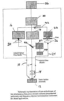
Figure 1 illustrates a schematic diagram of a first embodiment of a
simultaneous frequency-domain infrared photothermal radiometry and
frequency-domain luminescence instrument for dental applications according to
the present invention;
Figure 2 is a schematic diagram of a second embodiment of a
simultaneous frequency-domain infrared photothermal radiometry and
frequency-domain luminescence instrument for dental applications constructed
in accordance with the present invention for treating and restoring carious
teeth;
Figures 3a to 3d show simultaneous luminescence and FD-PTR images
at f=20 Hz in which Figure 3a) luminescence amplitude; Figure 3b) PTR
amplitude; Figure 3c) PTR phase; and Figure 3d) PTR amplitude with peaks
sliced off;
Figures 4a and 4b show the phase and amplitude plots respectively of an
ac luminescence response in the frequency-domain for a healthy and carious
spot on a human tooth in which the excitation source was a 488 nm Argon Ion
laser; and
Figures 5a and 5b show the phase and amplitude plots respectively of the
CA 02314691 2000-07-28
photothermal response in the frequency-domain for a healthy and carious spot
on a human tooth in which the excitation source was 488 nm Argon Ion laser;
DETAILED DESCRIPTION OF THE INVENTION
In the present invention, frequency-domain infrared photothermal
radiometry (FD-PTR) and modulated laser luminescence (FD-LM) are coupled to
produce complementary coupled dynamic dental diagnostic tools for quantifying
cracked and carious enamel. The use of dynamic depth profilometric imaging
using simultaneous frequency - domain infrared photothermal radiometry and
laser luminescence to study and image cracks and defects in human dental
enamel is very advantageous for several reasons. The combination of FD-LM
and FD-PTR diagnostic methodologies makes available four signal channels
(two amplitudes and two phases) instead of one featured by the state-of-the-
art
commercial do luminescence diagnostic methodologies. The correlation of
simultaneous data from four channels increases the diagnostic strength of the
technique substantially over the current single-signal do luminescence
instruments.
For an image to be formed, either the source or the detector must be
localized. Photothermal imaging generally falls into the category of scanned
microscopy with a localized source. The current present method is based on
low-fluence PTR detection microscopy [L. Nicolaides, M. Munidasa and A.
Mandelis, "Thermal-wave diffraction tomographic microscopy", Djordjevic and
11
CA 02314691 2000-07-28
Reis (eds): Topics On Non-Destructive Evaluation Series Vol. 3, pp 65-69
(1998)], which detects the emission of infrared radiation from a heated region
of
the sample without thermally altering the sample. A temperature oscillation
due
to modulated heating causes a variation in the thermal emissions, which is
monitored using an infrared detector. The temperature modulation allows
thermal energy to reach the surface diffusively from a depth approximately
equal
to a thermal wavelength,
~,~n(.f ) = 2n a l of
where a is the material thermal diffusivity [cm2/s] and f is the laser beam
modulation frequency. Scatterers located within a fraction of a thermal
wavelength from the source dominate the contrast of radiometric images. In
this
way, when the thermal wavelength is varied, e.g. by changing the laser-beam
modulation frequency, the region of the specimen that contributes to the image
is also varied. In turbid media such as teeth, the signal is controlled by
both the
optical diffusion (scattering) depth LS~ = 1/ps~ , where ps~ is the scattering
coefficient [cm-'] and the thermal diffusion length, L~n(f) = A6(~~2n as
disclosed in
A. Mandelis, L. Nicolaides, Y. Chen and I. A. Vitkin, "Optical property
determination of turbid media using frequency-domain infrared photothermal
radiometry, in Biomedical Optoacoustics, A. A. Oraevsky, Ed., SPIE vol. 3916,
Belligham, WA, pp. 122-129 (2000).
12
CA 02314691 2000-07-28
The basic ingredients of a FD-PTR and/or FD-LM dental microscope are
a source of energy, a physical scatterer (the tooth) and a detector of the
radiation scattered by the tooth. A convenient source of energy is the laser
beam, which can be easily modulated and focused to yield a coherent localized
energy source.
A block diagram of an apparatus for inspection of defects and/or caries on
samples of dental nature using laser PTR and modulated luminescence as a
preferred (but not sole) embodiment of the present invention will now be
described with reference to Figure 1. A heating and luminescence exciting
continuous-wave (CW) or pulsed laser 10 of suitable wavelength encompassing,
but not restricted to, the ultraviolet (UV) to infrared (IR) spectral range,
with
modulated intensity (power) in the mW to a few-Watt range, produces a laser
beam 11 is directed onto the surface of a tooth 12 using focusing optics 14.
The
blackbody radiation and luminescence signals emitted by the surface and
throughout the bulk of the tooth 12 are collected and focused onto an infrared
detector 16 (using an infrared optical fiber bundle 18 and focusing optics 20)
and a photodiode detector 22 (using an optical fiber bundle 24 and focusing
optics 26), respectively. Exemplary infrared optical fiber technology that may
be
used includes bundles of silver-halide fibers suitable for thermal imaging as
disclosed in E. Rave, D. Shemesh and A. Katzir, "Thermal imaging through
ordered bundles of infrared-transmitting silver-halide fibers", Appl. Phys.
Lett. 76,
1795 (2000). Detector 16 may be a liquid-NZ or thermoelectrically cooled
13
CA 02314691 2000-07-28
HgCdTe (e.g. EG & G Judson model J15D16-M204) with an active area of 1
mm2 or less and a spectrally sensitive range of 2-10 pm. Other non-cryogenic
IR
detectors such as pyroelectric sensors or Golay cells may be substituted for
the
HgCdTe detector, as required. An anti-reflection (AR)-coated Ge window with a
transmission bandwidth of 2-13 Nm is mounted in front of infrared detector 16
(which includes a pre-amplifier) to block any visible radiation from the pump
laser 10. The pump spot diameter of the laser beam 11 on the surface of tooth
12 is typically ca. 30-50 pm. The photothermal signal, which is proportional
to
the change of the IR radiation emitted from an area viewed by detector 16 is
amplified by a preamplifier (not shown) included with the infrared detector
(e.g.
EG & G Judson model PA-101 ) before being sent to a digital lock-in amplifier
30
(e.g. Stanford Research Systems, Model SR 850).
The ac luminescence emitted by the tooth 12 is collected with optical fiber
bundles and directed to photodetector 22, the output of which is also fed into
the
same or a different lock-in amplifier 30. A computer controlled or manual
switch
32 may be located between the outputs of detectors 16 and 22 sequentially
feeding each signal to a single two-phase lock-in amplifier 30 and storing the
data in a computer 36. Lock-in amplifier 30 is interfaced with computer 36 so
that
the frequency scan and data acquisition and storage are automated using
suitable software. All these electronics can be compacted and simplified into
customized electronics for single or discrete frequency applications or for
separate FD-PTR or FD-LM embodiments, as desired. The computer 36 or an
14
CA 02314691 2000-07-28
equivalent substitute digital readout device will give the clinician a real
time
reading of the status of the tooth surface and this information can also be
stored
in the computer for future reference.
An optical reference signal may be obtained using a beam splitter 40 and
a silicon photodiode 42 as monitors of the pump laser 10 intensity. A light-
emitting-diode (LED) readout 44 can provide the clinician with an indication
of
the integrity of the laser source and the onset of failure. Alternatively,
another
embodiment of the invention will use the ratio of the PTR and/or LM amplitude
with the photodiode 42 output to keep the signal outputs independent of laser
source intensity. Yet another embodiment of the invention will only use the
ratio
of the PTR and LM signal amplitudes and the difference of their respective
phases at two (or more) predetermined modulation frequencies as normalized
signals to cancel out all effects of laser source power fluctuation and
instrumental frequency dependencies (transfer function). Another embodiment of
the invention may use the ratio of PTR and/or LM amplitudes and difference of
respective phases from a carious or cracked tooth with that from a healthy
location of the same tooth (used as a reference) as determined by the
attending
dentist.
A further embodiment of the invention involves a step-functional pulse
illumination of duration ~ in the radiometric experimental set up. This can be
used for depth evaluation of the dentin-enamel junction. The step-functional
pulse illumination can be generated using a pulse generator to drive the
acousto
CA 02314691 2000-07-28
-optic modulator.
The apparatus shown in Figure 2 includes all the elements of the
apparatus of Figure 1 and in addition includes a laser 40 (or multiple lasers)
emitting in the UV to IR spectral range through optical fiber bundles 42 for
the
removal of carious tooth material, preparation of the tooth to receive a
direct
placed restorative material and the curing of a light cured or dual cured
composite filling material.
It will be appreciated by those skilled in the art that numerous other
configurations for repetitively heating samples and measuring the resulting
photothermal radiometric and luminescence signals may be used. The above
examples are meant to be non-limiting and illustrative only.
1 ) Method for Detecting Cracks in Teeth
The apparatus of Figure 1 has been used to detect sub-surface and near-
surface cracks in teeth using scanning imaging of the affected area and
setting
the modulation frequency to optimally image the cracked region. Ideally, the
probing centroid (determined as the weighted mean between the thermal
diffusion length L,h(f) and the scattering length, LS~) must be adjusted so as
to be
approximately equal to the depth where the sub-surface crack is located.
Alternately, frequency scans of the cracked region can be taken and a
comparison made with similar scans from a healthy location on the same tooth.
Studies by the inventors have shown that the full ac luminescence amplitude
range between good and cracked enamel is less than a factor of 2 and the
16
CA 02314691 2000-07-28
luminescence phase exhibits clear indications of the crack presence in the
frequency range above 100 Hz. On the other hand, the FD-PRT amplitude from
cracked teeth can increase by as much as 2 orders of magnitude over that from
healthy enamel, while the PTR phase exhibits strong changes in shape over the
entire dc- 100 kHz frequency range.
As an example of the potential of the combined ac techniques in
diagnosing dental sub-surface cracks inside the enamel, simultaneous PTR and
luminescence images were obtained at different modulation frequencies and in
all reported images, the signal ranges between high (black) and low (light
gray).
A flat enamel slice with a single 15 Nm wide transverse crack, 2-mm thick and
6mm x 10mm in size was imaged at f=20 Hz. The aim was to show the intrinsic
features of, and anti-correlation between, PTR and luminescence images.
The results of a 0.5mm x 0.5mm image of the flat enamel slice with a near
vertical sub-surface crack are shown in Figures 3a to 3d. The luminescence
image shown in Figure 3a appears to be sensitive to the presence of the crack;
in the cracked region the luminescence signal is low (light gray) whereas in
the
(nearly) intact region the luminescence is relatively high (gray). Within the
crack
region, luminescence photon emission of several wavelengths characteristic of
the enamel chromophores is essentially absent due to the material structural
destruction. As a result most of the incident energy decays nonradiatively,
yielding a strong photothermal radiometric signal. Conversely, in the intact
part
of the enamel the luminescence is significantly enhanced, while the
17
CA 02314691 2000-07-28
photothermal contribution is decreased. The two images together represent the
expected balance of excited-state energy release between a radiative
(luminescence) and a nonradiative (thermal-decay) dynamic process. The PTR
image is the result of thermal-wave generation in the tooth and thus consists
of
two channels; amplitude and phase, Figures 3 (b-d). In turbid media these
channels carry thermal transport information within approximately one thermal
centroid below the surface. The thermal diffusion centroid is determined as
the
"center-of-mass" among thermal diffusion length, ~~h/2n optical absorption
depth
and optical scattering mean-free-path in the bulk of the material.
Photothermal amplitude is generally more sensitive to surface property
variations, such as the reflectance, whereas phase is largely insensitive to
the
optical properties of the surface and probes a larger depth range [G. Busse,
"Optoacoustic and photothermal inspection techniques", Appl. Opt. 21, 107
(1982)] into the material. In Figure 3(b) the PTR amplitude exhibits two "hot
spots" in the defective enamel. These two spots are also seen in phase, Figure
3(c), confirming that the extent of these regions of the crack is deeper into
the
enamel. From optical observation of the tooth after the scan it is estimated
that
the penetration of the crack spots is 300 Nm. The luminescence image shown in
Figure 3(a) however shows the crack damage to be uniform throughout the
extend of the crack. This is probably due to the influence of enhanced optical
scattering at the crack leading to photon diffusion and "blurring" of the
luminescence emission from dental enamel and points to the major difference
18
CA 02314691 2000-07-28
between the two imaging principles: PTR images depth profiles of sub-surface
heat sources; luminescence does not, but is affected by image "blurring" due
to
photon scattering at the crack. It turns out it is also affected by photon
emission
delay processes which are characteristic of the material (enamel).
Figures 3a to 3d further point to the other major difference between the
two techniques: the superior dynamic range of the PTR amplitude. For this
reason, the image in Figure 3(b) is sliced to allow the visualization of other
features, the PTR intensity of which is much lower than the peaks of the
defect
regions. The sliced image is seen in figure 3(d), whose features are now
comparable to the PTR phase, Figure 3(c). On the contrary, the luminescence
amplitude is essentially continuous along the crack and shows neither the
detailed morphology of the cracked region, nor any similarly great signal
variations from the surrounding regions.
Studies by the inventors of FD-LM as a diagnostic of dental cracks have
shown that FD-LM is a dental imaging method of superior contrast to the
conventional do luminescence, specifically at the enamel-dentin interface. In
turn, the depth profilometric character of FD-PTR was found to be superior to
that of FD-LM, in terms of defective enamel information obtained at different
depths and also in terms of enamel absence and presence of dentin at the
enamel-dentin interface. Some degree of depth profilometry has been exhibited
by FD-LM, primarily through the depth distribution of the two luminescence
decay characteristic relaxation lifetimes (~ ms and ~ps) discovered in the
19
CA 02314691 2000-07-28
behavior of the FD-LM phase, see Figure 3a. The longer relaxation lifetime
appears to be associated with hydroxyapatite and almost never varies, whereas
the shorter one varies with laser fluence (a behavior similar to excited-state
quenching in optical materials, to which PTR is sensitive) and with the crack
density (or the carious state) of the tooth.
2) Method for Detecting Dental Caries and Defects in Teeth
The method of the present invention is based on low-fluence
photothermal radiometric detection and modulated luminescence microscopy,
which detects the emission of infrared radiation from a heated region of the
sample without thermally altering it. A temperature oscillation due to
modulated
heating causes a variation in the thermal emissions, which is monitored using
an
infrared detector. The temperature modulation allows for thermal energy to
reach
the surface diffusively from a depth approximately equal to a thermal
wavelength, where a is the material thermal diffusivity [cm2/s] and f is the
laser
beam modulation frequency. Figures 4a and 4b show the phase and amplitude
plots respectively of an ac luminescence response in the frequency-domain for
a
healthy and carious spot on a human tooth in which the excitation source was a
488 nm Argon Ion laser. The effect of caries (demineralization) of a tooth on
FD-
LM, is to suppress the absolute amplitude throughout the entire frequency
range
(see Figure 4b) thus rendering a calibrated relative scale of amplitudes
between
healthy and carious dental tissue a reasonable measure of the carious state.
The FD-LM phase exhibits little differentiation between healthy and carious
CA 02314691 2000-07-28
tissue up to approximately 1 kHz, as observed in the almost equal slopes of
the
two traces in Figure 4a. The high-frequency end, however, changes
significantly
depending on the carious state and can be used for calibration and / or
imaging
purposes.
Figures 5a and 5b show the phase and amplitude plots respectively of
the photothermal response in the frequency-domain for a healthy and carious
spot on a human tooth in which the excitation source was 488 nm Argon Ion
laser. Here the amplitude of the PTR signal from carious teeth is seen to
increase by orders of magnitude compared to healthy dental tissue. Also, the
PTR phases between carious and healthy dental tissue vary substantially in
shape and absolute value. Furthermore, the PTR phase is, in principle,
independent of the emissivity of tooth surfaces, thus comprising an ideal
imaging
channel of sub-surface caries. These features render PTR into a very sensitive
dental caries diagnostic technique, which, when properly calibrated, can yield
information
The amplitude results of Figures 4b and 5b show that the radiometric
signals at low excitation wavelengths (488 - 514 nm) are in general anti-
correlated with the luminescence signals, as a result of the nature of the two
physical signal generation processes. The radiometric signal channel has a
much superior dynamic (signal resolution) range that helps distinguish between
intact and damaged sub-surface structures in the enamel and dentin. The
radiometric signal (amplitude and phase) adds the capability to produce dental
21
CA 02314691 2000-07-28
images with accurate defect localization, delineation and resolution
commensurate with the laser beam size (30-50 pm). The FD-PTR images
(amplitude and phase) at a fixed modulation frequency have depth profilometric
features. ac luminescence frequency responses from enamel, dentin and
hydroxyapatite exhibit two modulated relaxation lifetimes, the longer of which
(~ms) is common to all three materials. The luminescence intensity is
proportional to the density of luminescence chromophores in the tooth, as well
as to their particular location. Therefore, relative FD-LM amplitudes are
characteristic of the carious state of a tooth, with the ~,us decay lifetime
providing additional information on sub-surface defects, cracks and the onset
of
caries.
The method and device disclosed herein may be advantageously used for
several diagnostic dental applications including: scanning teeth intraorally
to
detect caries and classify caries or the integrity of the enamel or cementum
surface, to classify the health and integrity of the enamel at the base of
occlusal
fissures, to classify the health and integrity of enamel or cementum surface
of
the tooth, study defects around the margins of restorations, locate the
presence
of cracks on the enamel or cementum surface, and locate and characterize
cracks in dentin on prepared teeth.
A further variation on the method of the present invention involves
combining the diagnostic instrument with another laser in the same
instrumentation package to create instrumentation for both the diagnosis of
tooth
22
CA 02314691 2000-07-28
defects and treatment thereof, including preparation of the defective portion
of
the tooth as well as the curing of various filling materials (e.g. composite
resin
based filling materials) and the preparation of the tooth surface to receive
these
materials.
For example, if the data and clinical expertise indicates the presence of
pathology, providing the ability to treat the tooth by using lasers that are
presently on the market to: remove the decayed or carious tooth material;
prepare the tooth using known principles of tooth preparation design; cure or
set
the light-cured or dual-cured composite material in the tooth preparation
restoring the tooth to form and function, using suitable laser-fluence
delivery
protocols through pulse-waveform engineering, for precise, optimized control
of
optical radiation delivery and thermal energy generation.
The use of laser-pulse-intensity waveform engineering may be used in the
present invention for optimization of the delivery of optical curing radiation
and
minimization of thermal load effects to the tooth. This may be achieved by
means of an optimal duty-cycle program over each laser-beam modulation
period, designed to maximize exposure to laser light while minimizing heat
generation in the tooth.
In addition, the present method and apparatus may be combined with
current technology to create an instrument that will allow the clinician to:
diagnose tooth decay, remove carious tooth material and prepare a standard
cavity preparation that is of the proper shape and form for a filling material
and
23
CA 02314691 2000-07-28
to etch or roughen the surface of the prepared tooth using a laser, place and
cure a light cure or dual cured composite filling material, the placement and
curing of a light cured composite or direct placement fissure sealing
material.
As mentioned in the Background of The Invention above, a variety of
methods have been developed for using lasers to treat carious tooth
structures.
Yessik et al. (U. S. Patent No. 5,621,745 April 15, 1997) describes one method
of using a modulated pulsed laser to remove carious tooth material. Kowalyk
(U.
S. Patent No. 5,281,141, January 25, 1994) describes a method for using a
Nd:YAG laser to treat and remove carious tooth material. These methods or
possibly another approach using the well-known principle of laser ablation [E.
C.
Benck, Z. Rong, S. H. Chen, Z. C. Tang and H. A, Schuessler, Appl. Phys. Lett.
58, 1476 (1991 ); and Appl. Surf. Sci. 48, 257 (1991 ); R. Srinivasan, B.
Braren
and R. W. Dreyfus, J. Appl. Phys. 61, 372 (1987); and G. Gorodetsky, T. G.
Kazayaka, R. L. Melcher and R. Srinivasan, Appl. Phys. Lett. 46, 828 (1985)]
may be combined in with the present apparatus to provide therapeutic tools to
the clinician to remove carious tooth material that had been found with the
present method.
Therefore, the foregoing description of the preferred embodiments of the
invention has been presented to illustrate the principles of the invention and
not
to limit the invention to the particular embodiment illustrated. It is
intended that
the scope of the invention be defined by all of the embodiments encompassed
within the following claims and their equivalents.
24