Note: Descriptions are shown in the official language in which they were submitted.
CA 02314785 2006-07-10
Surgical Instrument and Method for Endoscopic Tissue Dissection
Field of the Invention
~ o The present invention relates, in general, to the dissection and
retraction of
bodily tissue and, more particularly, to new devices and endoscopic methods
for
harvesting a blood vessel to be used as a coronary artery bypass graft.
Background of the Invention
is
Minimally invasive vessel harvesting has gained widespread acceptance in
the field of surgery as a method for obtaining graft vessels for coronary
artery
bypass graft (CABG) procedures. When using such a method, for example, a long
portion of the saphenous vein is removed from a patient's leg, operating
through
20 only one or a small number of short incisions in the leg. The vein is then
segmented
according to the number and type of grafts needed for the CAHG procedure.
A surgical technique for the removal of a vessel such as a saphenous vein is
disclosed in U.S. Patent Re. 36, 043 issued to ICnighton on January 12, 1999
25 (hereinafter, Knighton). In this procedure, the surgeon uses an endoscope
having a
lumen through it. A grasping instrument is inserted in the lumen in order to
gasp
the saphenous vein, which is then withdrawn into the Iumen of the endoscope.
The
endoscope is maneuvered along the length of the vein while side branches of
the
~ CA 02314785 2000-08-O1
- 2 -
vein are ligated and transected whenever encountered. Although this surgical
method provides for a minimally invasive technique, there are several
drawbacks
associated with it. First, in practicing this method, there is limited
visibility of the
saphenous vein and its side branches because viewing is limited to the
immediate
s area directly in front of the endoscope. Second, the illumination within the
subcutaneous space created by this type of endoscope is also limited to the
light
emitted directly at the distal portion of the endoscope. A third drawback to
the
described method is that the side branches of the saphenous vein limit the
maneuverability of the endoscope. This limited maneuverability is because the
outer
i o edge of the endoscope body is prevented from advancing along the trunk of
the
saphenous vein until the encountered side branches are ligated and transected.
Once
free, the endoscope is then maneuvered until the next side branch is
encountered.
Moreover, it has been found that methods that use this type of endoscope
(having a
lumen) provide a restricted working space because the sidewalls of the
endoscope
~5 body confine the working instrumentation to a limited area. A fourth
drawback to
the vessel harvesting method described in Knighton is that it requires a
"three-
handed" approach. One hand is required to hold and maintain the endoscope in
position, a second hand is required to hold the free end of the transected
vessel with
a grasper, and a third hand (of an assistant) is required to dissect
connective tissue
2 o away from the vessel.
Ethicon Endo-Surgery, Inc., Cincinnati, Ohio, has developed and promoted
two very successful devices and an associated method for endoscopically
harvesting
blood vessels such as the saphenous vein. In this method, a surgeon (or
surgical
25 assistant) uses an optical tissue dissector known as the ENDOPATH SUBCU-
DISSECTOR optical dissector for separating subcutaneous tissue away from the
saphenous vein. Then the surgeon or assistant uses an optical retractor known
as the
ENDOPATH SUBCU-RETRACTOR optical retractor for retracting the dissected
CA 02314785 2006-07-10
- 3 -
tissue away from the saphenous vein. Both of these devices have a transparent,
concave working head having a spoon shape. The optical retractor has a larger,
working head, however, than the optical dissector. The concave, working head
defines a working space for the end effectors of an instrument such as a
gasper, a
s scissors, or a clip applier. The optical dissector and optical retractor
allow the
surgeon to see the tissue on which is operated. These devices (hereinafter,
Knight
devices, Knight optical dissector, Knight optical retractor) and a surgical
method for
their use have been issued to Knight, et al, and are disclosed in U.S. Patent
5,667,480 issued on September 16, 1997 and in U.S. Patent 5,722,934 issued on
i o March 3, 1998.
The Knight optical dissector and retractor are each used with a thirty-degree
endoscope in which the viewing angle of the distal end of the scope is slanted
30
degrees from the longitudinal axis of the instrument. The field of view is
therefore
is directed ahead and to one side of the axis. This type of endoscope is ideal
for use
with the spoon shaped heads of the Knight devices because the surgeon desires
to
view the tissue directly ahead of the head and beneath the opening of the head
where
the tissue may be operated on.
2o In U.S. Patent 5,902,315 issued to DuBois on May 11, 1999,
a device (hereinafter, DuBois device) is
described for dissecting and retracting a blood vessel from subcutaneous
tissue. The
DuBois device is similar to either of the Knight devices, and has the addition
of a
fluid carrying system for purging particulate matter from the working space of
the
2s concave head of either the optical dissector or optical retractor. A fluid
flow (of
carbon dioxide gas, for example) is used to purge smoke and/or mist from the
enclosed working space in order to maintain visualization of the tissue being
operated on. Particulate matter accumulates due to the use of electrosurgical
or
- ~ ~ CA 02314785 2000-08-O1
- 4 -
ultrasonic cutting devices, whereas condensation of moisture in the working
space
occurs due to the temperature differential between the inside and outside of
the
patient's body.
s The Knight and DuBois devices and methods for their use for harvesting
vessels represent a significant advance in the surgical art. Nevertheless;
widespread
use of these devices and methods has helped to clarify even more the needs of
the
surgeon for harvesting blood vessels. For example, for some surgeons or
physician
assistants, the repeated application of force required to advance the concave
head of
to the Knight optical dissector in order to separate tissue from the vein can
become
physically tiring. This is especially true when harvesting a long (over 18
inches)
portion of vein such as would be needed for a multiple CABG procedure. For
these
surgeons/assistants, the time required to dissect the vein can be several
minutes
longer than the time required by others who are better able to exert the
manual
15 dissection force required during the procedure. What is needed, therefore,
is a device
and method to reduce the initial dissection force required for separating the
vein
from surrounding tissue. Then the Knight or Dubois devices having the
necessary
concave heads for creating a working space could be inserted into the tissue
more
easily than before. Furthermore, the initial dissecting device and method
should be
2 o used with the same, thirty-degree endoscope as is needed for the Knight
devices to
minimize the amount (and cost) of visualization equipment needed in the
operating
room.
In recent years, a number of penetrating optical instruments, sometimes
2 s referred to as optical trocars, have been developed for gaining access
into a cavity in
the surgical patient. One of the earliest examples is disclosed in U.S. Patent
5,271,380 issued on December 21, 1993 to Riek, et al. This penetration
instrument
has a hollow shaft for receiving an endoscope, and a transparent, conical
distal end.
CA 02314785 2000-08-O1
- 5 -
Other examples of optical, penetration instruments are disclosed in the
following
U.S. Patents: 5,380,291 issued on January 10, 1995 to Kaali; 5,441,041 issued
on
August 15, 1995 to Sauer, et al; 5,423,848 issued on June 13, 1995 to
Washizuka.
All of these patents describe instruments having transparent, conical tips, or
the
equivalent. In U.S. Patent 5,569, 291 issued on October 29, 1996 to Privitera,
et al,
a conical-tipped optical trocar is also disclosed. It is suggested that this
surgical
instrument may be used in "tunneling techniques to provide access to a desired
surgical site remote from the point of entry" in connection with saphenous
vein
harvesting (see col. 4, line 43-44.)
In all of the references for optical, penetrating instruments cited in the
present disclosure, the apex, or distal-most portion of the conical-shaped
tip, lies on
the central longitudinal axis of the instrument. These types of instruments
are
intended for use primarily with a zero-degree endoscope in which the field of
view
is directly ahead of the distal end of the endoscope. When the zero-degree
endoscope is inserted into the optical, penetrating instrument, the apex is
centered in
the field of view, and it is possible to view images all around the apex
within the
field of view. If any of these conical-tipped instruments were to be used with
a
thirty-degree endoscope, the apex of the conical tip would be off center of
the field
of view, and only images appearing on one side of the conical tip could be
visualized. This would present a problem to the surgeon if such an arrangement
were being used to "tunnel" along a blood vessel. Only one side or the other
of the
conical tip could be used as a window to see tissue. If the blood vessel being
dissected from tissue happened to be on the "blind side" of the tip, then the
surgeon,
for example, may not be able to see side branches of the vessel as they are
encountered. If side branches are "skipped" and not ligated and severed
cleanly
from the main trunk of the blood vessel, there would be significant danger of
tearing
side branches during the dissection of more distal portions of the blood
vessel. It is
CA 02314785 2000-08-O1
- 6 -
clearly advantageous to be able to visualize all tissue adjacent to the
optical
penetrating tip. What is needed, therefore is an surgical instrument and
method,
which can be used as an initial dissection or "tunneling" instrument for
vessel
harvesting in combination with a thirty-degee endoscope. The surgical
instrument,
furthermore, should have an optical penetrating tip that allows visualization
of all
tissue adjacent to the optical penetrating tip.
Summary of the Invention
io The present invention is a surgical instrument for optically penetrating
bodily
tissue to create an initial body cavity. The surgical instn~ment comprises an
elongated hollow shaft having a longitudinal axis, a proximal end, a distal
end, and a
lumen therethrough. The surgical instrument further comprises an optical
penetrating tip having a cylindrical portion attached to the distal end of the
hollow
shaft and a tapered portion extending distally therefrom. The tapered portion
has an
apex spaced laterally apart from the longitudinal axis of the hollow shaft,
thus
allowing the surgeon to visualize all tissue adjacent to the tapered portion
of the
optical penetrating tip while being used in combination with an endoscope
having a
30-degree tip.
In a preferred embodiment, a handle is attached to the proximal end of the
hollow shaft for manipulating the surgical instrument through an incision of
the
surgical patient. The tapered portion of the optical penetrating dp has an
upper
surface blended into a lower surface, and the upper surface is sloped with
respect to
the longitudinal axis of the hollow shaft. The upper surface has an average
inclination axis when viewed from the side and the average inclination axis
forms an
inclination angle with the longitudinal axis of the hollow shaft of between 15
and 75
degees. A preferred inclination angle is about 45 degees.
CA 02314785 2006-11-09
-
The surgical instrument further includes an endoscope for slidably
insertion into the lumen of the hollow shaft. The endoscope has a conical
field-of
view through the optical penetrating tip, whereby a central viewing axis of
the
field-of view is directed thirty degrees from the longitudinal axis of the
hollow
shaft, and the apex of the optical penetrating tip is approximately in the
center of
the field-of view of the endoscope.
The surgical instrument further includes at least one purge port in the distal
end of the hollow shaft fluidly connected to a flow source, such as carbon
dioxide
gas. Particulate matter and moisture is purged from a body cavity created by
the
optical penetrating tip while the surgical instrument is inserted in the body
cavity.
A method is provided for creating an initial body cavity alongside of a
vessel to be harvested from a surgical patient's body comprising the steps of
identifying a vessel to be removed, making an incision in the patient's body
near
the identified vessel, inserting a surgical instrument having an optical
penetrating
tip through the incision, optically penetrating the tissue along a side of the
vessel
with the optical penetrating instrument, and withdrawing the optical
penetrating
instrument from the body through the incision.
In one aspect of the invention, there is provided a surgical instrument for
optically penetrating bodily tissue to create an initial body cavity and
comprising:
an elongated, hollow shaft having a longitudinal axis, a proximal end, and a
distal
end, said hollow shaft having a lumen therethrough; an optical penetrating tip
having a cylindrical portion attached to said distal end of said hollow shaft
and a
tapered portion extending distally therefrom, said tapered portion having an
apex
spaced laterally apart from said longitudinal axis; and a pair of dissecting
blades
molded onto or separately attached to the tapered portion of the optical tip,
the
blades extending from the apex in approximately the proximal longitudinal
direction.
CA 02314785 2006-11-09
- 7a -
In another aspect of the invention, there is provided a use of the instrument
described above for creating an initial body cavity alongside of a vessel to
be
harvested from a surgical patient and body.
Brief Description of the Drawings
The novel features of the invention are set forth with particularity in the
appended claims. The invention itself, however, both as to organization and
methods of operation, together with further objects and advantages thereof,
may
best be understood by reference to the following description, taken in
conjunction
with the accompanying drawings in which:
CA 02314785 2000-08-O1
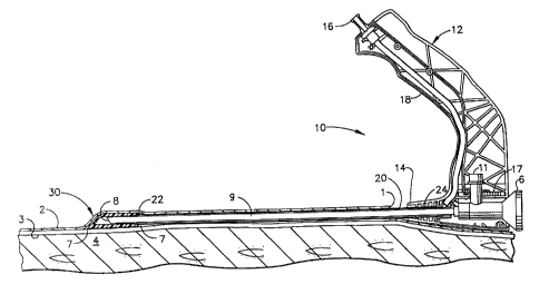
Figure 1 is a sectional view of the present invention, an optical dissector
(also
referred to as a surgical instrument), as it is used in combination with an
endoscope
and is positioned between tissue layers of a surgical patient;
Figure 2 is an isometric view of a first embodiment of an optical tip of the
optical
dissector shown in Figure 1;
Figure 3 is a partial, isometric view of a proximal end of the optical tip
shown in
to Figure 2;
Figure 4 is an isometric view of a distal end of a shaft of the optical
dissector shown
in Figure 1;
Figure 5 is a top view of the optical tip shown in Figure 2 and assembled on
the
shaft with an endoscope having a 30-degree tip inserted therein;
Figure 6 is a side, sectional view of the optical tip, shaft, and endoscope
shown in
Figure 5;
Figure 7 is a bottom view of the optical tip, shag, and endoscope shown in
Figure 5;
Figure 8 is an enlarged, distal end view of the optical tip shown in Figure 5;
2s Figure 9 is an enlarged, proximal end view of the optical tip shown in
Figure 5;
CA 02314785 2000-08-O1
_ g _
Figure 10 is a top view of a second embodiment of an optical tip for the
optical
dissector shown in Figure 1, and shown assembled on the shaft with an
endoscope
having a 30-degree tip inserted therein;
Figure 11 is a side, sectional view of the optical tip, shaft, and endoscope
shown in
Figure 10;
Figure 12 is a bottom view of the optical tip, shaft, and endoscope shown in
Figure
I 0;
Figure 13 is an end view of the optical tip shown in Figure 10;
Figure 14 is a side, sectional view of an optical dissector having a conical
tip similar
to a penetrating tip of a prior art instrument disclosed in U.S. 5,569,291, as
it may be
~5 used with an endoscope having a 30-degree tip for harvesting a vessel; and
Figure 15 is a side, sectional view of the distal portion of the optical
dissector shown
in Figure 1, wherein the optical dissector is used with an endoscope having a
30-
degree tip for harvesting a vessel.
Detailed Description of the Invention
Figure 1 is a side, sectional view of a first embodiment of the present
invention, an optical dissector 10 (also referred to as a surgical
instrument). Optical
dissector 10 is positioned through incision 1 and between upper tissue layer 2
and
lower tissue layer 4 of a surgical patient, and is shown being used in
combination
with an endoscope 6 having a 30-degree tip 8 to create an initial body cavity
7
CA 02314785 2000-08-O1
alongside blood vessel 3. Optical dissector 10 comprises a hollow, elongated
shaft
20 having a distal end 22 and a proximal end 24. Shaft 20 is preferably made
of
stainless steel tubing. In this embodiment, a plastic handle 12 for gripping
and
manipulating optical dissector 10 is attached to proximal end 24 of shaft 20.
Handle
12 comprises an ergonomically shaped grip 18, a nose 14 for attachment to
shaft 20,
and a connector 16 for attaching optical dissector 10 to a flow source (not
shown).
Optical dissector 10 further comprises a hollow, transparent, optical tip 30
attached
to distal end 22 of shaft 20. Endoscope 6 has an elongated, optical shaft 9
slidably
inserted into shaft 20 so that a 30-degree tip 8 of endoscope 6 is positioned
inside of
optical tip 30 of optical dissector 10. An endoscope retaining guide 17 is
provided
in handle 12 for holding and aligning stem 11 of endoscope 6 in an upright
position
as shown, so that 30-degree tip 8 of endoscope 6 is oriented in a downward
position
as shown. As will be described for Figure 15, this alignment of the endoscope
6 is
advantageous for viewing tissues adjacent to optical tip 30.
Figure 2 is an isometric view of optical tip 30, a first embodiment of the
present invention and shown in Figure 1. Optical tip 30 is asymmetrically
shaped
and comprises a tapered portion 39 having an apex 32. Optical tip 30 further
comprises a cylindrical portion 38 and a proximal end 34. Optical tip 30 is
optically
2 o transparent and has a uniformly thick wall in tapered portion 39. Optical
tip 30 is
preferably made of a rigid, medical grade, injection moldable plastic such as
polycarbonate.
Figure 3 is an isometric view of proximal end 34 of optical tip 30, showing a
lumen 29 therein for attachment to distal end 22 of shaft 20 shown in Figure
4. In
this embodiment, four dovetail shaped ribs 36 are formed in proximal end 34 of
optical tip 30 for attachment to four shaft flutes 26 formed irrto distal end
22 of shaft
20. This type of attachment is not intended to be detachable by the user.
Other
CA 02314785 2000-08-O1
- 11 -
types of attachments are possible, including those types in which the user may
detach optical tip 30 from shaft 20. This may be advantageous, for example,
for
surgical procedures requiring multiple versions of optical tip 30, each
version having
dissecting and/or optical characteristics specifically provided for particular
steps of
the surgical procedure. For all types of attachment, however, it is important
that
optical tip 30 not come oii: of shaft 20 while optical dissector 10 is
positioned inside
the body cavity of the patient.
Figure 4 shows a lumen 23 extending through the entire length of shaft 20
o for slidably inserting endoscope 6. Figure 4 also shows a purge port 25
located
proximal to where proximal end 34 of optical tip 30 would be positioned once
assembled. At least one purge port 25 is provided and fluidly communicated to
connector 16 of handle 12 as described for the DuBois device previously
referenced
in U.S. Patent 5,902,315. Purge port 25 allows a flow of fluid, such as carbon
dioxide gas, to be introduced into body cavity 7 of the patient during the
surgical
procedure. The fluid then escapes body cavity 7 along the outside of shaft 20
and
out of incision I (see Figure 1). This flow of fluid purges particulate matter
including, for example, smoke and mist resulting from the use of
electrosurgical or
ultrasonic cutting instruments, which may be used in combination with optical
2o dissector 10. This flow of fluid also helps to dry moisture forming on
optical tip 30
due to condensation of water inside body cavity 7, thus improving the ability
of the
operator to view tissue adjacent to optical tip 30.
Figure 5 is a top view, Figure 6 is a side, sectional view, and Figure 7 is a
bottom view of optical dissector 30 shown in Figures 1 and 2, assembled onto
distal
end 22 of shaft 20. Optical shaft 9 of endoscope 6 is shown slidably inserted
into
shaft 20. A curved, upper surface 31 (see Figure 5) of tapered portion 39
blends
with a lower surface 35 (see Figure 7). Upper surface 31 and lower surface 35
are
CA 02314785 2000-08-O1
- 12 -
rounded or non-planar, that is, neither has a flattened area. A 30-degree tip
8 of
endoscope 6 is positioned within an optical tip chamber 33 and is oriented to
view
ahead and downwardly. The importance of this orientation of 30-degree tip 8
(also
referred to as a distal viewing tip) is best understood by referring to
Figures 14 and
s 15. Figure 14 shows a conical tip 60 having a distal point 63 centered on a
longitudinal axis 50. Conical tip 60 is shown assembled onto distal end 22 of
shag
20, and used in combination with endoscope 6 for separating blood vessel 3,
having
side branch 5, from lower tissue layer 4. Endoscope 6 has 30-degree tip 8,
which
has a field-of view 62 centered on a viewing axis 64. The width of field-of
view 62
to shown is not limited to what is illustrated in Figure 14, and may be more
or less
depending on the optical characteristics of endoscope 6. Conical tip 60 is
similar in
shape to the optical trocar described in U.S. Patent 5,569,291, and is
representative
of the symmetrically shaped optical tips of the prior art. As is apparent in
Figure 14,
side branch 5 and lower tissue layer 4 are not contained within the field-of
view 62
is of endoscope 6. If endoscope 6 were rotated 180 degrees about axis 50 so
that 30-
degree tip 8 was pointed downwardly instead of upwardly, then blood vessel 3
would not be contained in field-of view 62. In order to view blood vessel 3,
side
branch 5, and lower tissue layer 4 simultaneously when using conical tip 60,
therefore, endoscope 6 must be provided with a zero-degree tip (not shown). A
2o zero-degree tip views "straight-ahead" in the distal direction, and would
allow poi
63 to be approximately centered within field-of view 62.
Figure 15 shows the distal portion of optical dissector 10 of Figure 6 used in
combination with 30-degree tip 8 of endoscope 6 having an angled field-of view
66
2s and an angled viewing axis 68. As Figure IS illustrates, apex 32 of optical
tip 30 is
approximately in the center of angled field-of view 66 and closely aligned
with an
angled viewing axis 68. A viewing angle 67 is between angled viewing axis 68
and
longitudinal axis 50. Blood vessel 3 and side branch 5 are also contained in
angled
CA 02314785 2000-08-O1
- 13 -
field-of view 66. The user may, therefore, advance optical dissector 10 while
visualizing both blood vessel 3 and lower tissue layer 4 as they are
separated. The
user is also able to see side branch 5 as it is encountered.
Returning now to Figure 6, the profile of upper surface 31 is shown to have
an average inclination 52 with respect to longitudinal axis 50 of optical
dissector 30.
An inclination angle 53 between average inclination 52 and axis SO is shown in
the
embodiment in Figure 6 to be approximately 45 degrees. Inclination angle 53,
however, may vary substantially. A smaller inclination angle 53 (a more
tapered tip)
1 o advantageously reduces the force to "tunnel" into tissue. A larger
inclination angle
53 (a blunter tip) advantageously decreases the distance between 30-degree tip
8 and
the tissue being viewed. A compromise may be found, for example, in selecting
inclination angle 53 to be approximately in the range of 15-75 degrees. What
is
important to maintain, no matter what the value for inclination angle 53, is
that apex
32 is approximately centered in field of view 66 as shown in Figure 15.
Figures 8 and 9 are enlarged views of the distal and proximal ends,
respectively, of the optical tip 30 shown in Figures 5, 6, and 7. Figure 8
illustrates
how upper surface 31 is blended into lower surface 35 in this embodiment.
Figure 9
2 o shows how distal end 22 of shaft 20 is attached to ribs 36 of optical tip
30, providing
radial clearance for the slidable insertion of endoscope 6.
Figures 10, 11, 12, and 13 are orthographic views of the distal portion of a
second embodiment of the present invention. The second embodiment varies from
2 5 the first embodiment shown in Figures 5, 6, and 7 in that an optical tip
40 of the
second embodiment has a different shape than optical tip 30 of the first
embodiment.
Optical tip 40 comprises a cylindrical portion 48, a tapered portion 49, a
proximal
end 44 for attachment to shaft 20, and an apex 42 offset from longitudinal
axis 50.
CA 02314785 2000-08-O1
- 14 -
Optical tip 40 further comprises a flat, upper surface 41 blended with a lower
surface
45. Endoscope 6 having 30-degree tip 8 (also referred to as a distal viewing
tip) is
shown slidably inserted into a optical tip chamber 43. Purge ports ZS are
shown in
shaft 20 proximal to optical tip 40. Optical tip 40 further comprises a pair
of
dissecting blades 47 molded onto or separately attached to tapered portion 49.
Blades 47 are on opposite sides of tapered portion 49 and extend from apex 42
in
approximately the proximal longitudinal direction. Blades 47 are provided to
assist
in separating tissue layers, but are not sharp enough to cut tissue.
i o Method of Use
The optical dissector 10, also referred to as an surgical instrument, of the
present invention may be used in a wide variety of procedures requiring an
initial
penetration of tissue for creating a body cavity. One possible procedure is
for
i 5 harvesting a vessel, such as the saphenous vein, from a patiem so that the
vessel may
be used later as a coronary artery bypass graft on that patient. The optical
dissector
may be used for such a procedure in combination with the optical
dissector/retractor having a transparent, concave head (also referred to as
the DuBois
device) disclosed in U.S. Patent 5,902,315. A method for using optical
dissector 10
2 o to create body cavity 7 is described next while referring to Figures 1 and
15.
The surgeon first identifies blood vessel 3, such as the saphenous vein, to be
harvested. A marker pen may be used to trace the underlying location of blood
vessel 3 on the skin of the patiem. The surgeon then makes an incision 1 in
the
2s tissue near blood vessel 3 using a cutting tool such as a scalpel. Next the
surgeon
places optical dissector 10 through incision 1 and maneuvers optical tip 30
over
blood vessel 3, initially separating blood vessel 3 from upper tissue layer 2.
As side
branch 5 of blood vessel 3 is encountered, optical tip 30 is advanced
carefully past
' ' CA 02314785 2000-08-O1
- 15 -
side branch 5. Optical dissector 10 is advanced a short distance in the distal
direction along blood vessel 3, and then retracted partially in the proximal
direction,
creating body cavity 7 alongside blood vessel 3. This is repeated a plurality
of times
and each time optical tip 30 is advanced a little farther in the distal
direction until
body cavity 7 is approximately equal to the length of blood vessel 3 to be
harvested.
Optical dissector 10 is then withdrawn through incision 1. The surgeon may
then
proceed with the vessel harvesting procedure using, for example, an optical
retractor/dissector having a transparent concave head as disclosed in U.S.
5,902,315.
to
While preferred embodiments of the present invention have been shown and
described herein, it will be obvious to those skilled in the art that such
embodiments
are provided by way of example only. Numerous variations, changes, and
substitutions will now occur to those skilled in the art without departing
from the
invention. Accordingly, it is intended that only the spirit and scope of the
appended
claims limit the invention.