Note: Descriptions are shown in the official language in which they were submitted.
CA 02315013 2000-08-03
PIEZOELECTRIC MOTOR
BACKGROUND OF THE INVENTION
Field of the invention
The invention relates to piezoelectric devices and, more specifically,
piezoelectric
motors, being electric motors using piezo crystals for providing rotational
momentum
to a rotor part of the motor relative a stator part of the motor.
Descrietion of the Prior Art
A piezoelectric motor is known from US Patent 4,453,103, granted June 5, 1984,
comprising a stator and a rotor, which are in mechanical contact with one
another along
at least one cylindrical surface of friction interaction. Elastically curved,
longitudinally
elongated plates/pushers, which are set against the friction surface at one
end, and are
positioned at an angle to the same surface, while being anchored at the other
end,
either directly or via a metal membrane, to the cylindrical surface of the
ring
piezoelectric element with electrodes for exciting longitudinal oscillations
of the
perpendicular surfaces of friction interaction.
A piezoelectric motor (US Patent 4,959,580, granted September 25, 1990) is
also
known, possessing the same attributes, except that the pushers are at one end
anchored on the flat surface of the ring piezoelectric element.
The maximum power which can be supplied to the piezoelectric element of the
above
motors is determined by the maximum breaking strength of the piezoelectric
element
or the strength of the bond between the electrodes of the piezoelectric
element coating
and the ceramics, when the pushers are anchored on the piezoelectric element's
surface. A small diameter of the piezoelectric element will not allow a large
number of
pushers to be anchored in order to increase the motor's torque moment. Solving
the
above problems requires increasing the diameter of the piezoelectric element
and,
consequently, the piezoelectric element's volume, which significantly
increases the
motor's size and cost. The presence of recesses in the piezoelectric element
and the
thermal shocks that the piezoelectric ceramics is subjected to when the
pushers'
-1-
CA 02315013 2000-08-03
connections are being soldered on it, notably reduces the motor's reliability,
especially
in the modes of operation approaching the limit of tolerance. Moreover, such
is the
technology of anchoring pushers that it requires sizable expenditures when
each new
type of motor is introduced to the manufacturing process.
SUMMARY OF THE INVENTION
The main purpose of the invention is to provide a piezoelectric motor designed
so that
it would be possible to avoid direct connection between the pusherand the
piezoelectric
element.
It has been shown that if two flat ring plates are pressed against the surface
plate of the
piezoelectric element by means of a clamp, the plates together with the
piezoelectric
element will form a new oscillation system. The quality factor of the fist
resonance
oscillation mode is not lower (and at times higher) than that of the first
mode of the ring
piezoelectric element, with the resonance characteristics remaining
monofrequency, i.e.
acting as a single whole in regard to the oscillations of the piezoelectric
element with
the plates, but, since the piezoelectric element is drafted, its rupture
strength increases.
Besides, the motor's reliability and the maximum value of its pulse power also
increase.
The number of pushers can now be vastly augmented, as well as the motor's
starting
torque. All this is achieved with the minimum amount of piezoelectric ceramics
and at
but insignificant costs of technological rigging.
In the invention, a piezoelectric motor comprises a stator and a rotor, the
stator and the
rotor being in mechanical contact with one another along at least one
cylindrical friction
surface by means of curved, elastic and longitudinally elongated pusher
plates. The
pusher plates are held against the friction surface at a first end of the
pusher plates,
and arranged at an angle to the friction surface. Further, a piezoelectric
element is
connected to the rotor, according to a first embodiment of the invention. The
piezoelectric element has electrodes placed on opposing surfaces of the
piezoelectric
element, and is connectable to an alternating current source via the
electrodes, for
providing longitudinal oscillations in the piezoelectric element. A first ring
plate and a
second ring plate are arranged on opposite sides of the piezoelectric element,
so that
-2-
CA 02315013 2000-08-03
at least a portion of surfaces of the piezoelectric element are pressed
against surfaces
of the first ring plate and the second ring plate, respectively, by a clamping
device. In
this way, longitudinal oscillations are transferred into the first ring plate
and the second
ring plate from the piezoelectric element. At least one of the first ring
plate and the
second ring plate are in mechanical contact with a second end of the pusher
plates.
Three alternative methods of attaching the pusher plates to the ring plates
are preferred
for the first embodiment of the invention:
1 ) The pusher plates are anchored on the first ring plate at the second end
of the
pusher plates.
2) The pusher plates are anchored on the second ring plate at the second end
of
the pusher plates.
3) A first set of the pusher plates are anchored on the first ring plate at
the second
end of the first set of pusher plates and a second set of the pusher plates
are
anchored on the second ring plate at the second end of the second set of
pusher
plates.
Preferably, the clamping device is sound-insulated from at least one of the
first ring
plate and the second ring plate by means of a soundproofing device. The
soundproofing device is advantageously made of a soundproof material, for
example
rubber. The soundproofing device may further be made in the form of a thin-
walled
cylindrical membrane.
The electrodes of the piezoelectric element are either applied to flat
surfaces of the
piezoelectric element or applied to cylindrical surfaces of the piezoelectric
element.
The pusher plates are advantageously anchored with a first end in recesses in
the
piezoelectric element by drafting the recesses.
The rotor is advantageously in the shape of a barrel enclosed by the pusher
plates.
Alternatively, the rotor is in the shape of a cylinder enclosed by the pusher
plates.
_3_
CA 02315013 2000-08-03
Advantageously, either the stator or the rotor switches on the piezoelectric
element.
Preferably, the transfer of longitudinal oscillations into the first ring
plate and the second
ring plate from the piezoelectric element takes place via sound-conductive
gaskets
arranged between the piezoelectric element and the first ring plate and the
second ring
plate, respectively.
A second embodiment of the invention is a piezoelectric motor comprising a
stator and
a rotor, the stator and the rotor being in mechanical contact with one another
along at
least one cylindrical friction surface by means of curved, elastic and
longitudinally
elongated pusher plates. The pusher plates are held against the friction
surface at a
first end of the pusher plates, and arranged at an angle to the friction
surface. A
piezoelectric element is connected to the stator, the piezoelectric element
having
electrodes placed on opposing surfaces of the piezoelectric element, the
piezoelectric
element being connectable to an alternating current source via the electrodes
for
providing longitudinal oscillations in the piezoelectric element. Further, a
first ring plate
and a second ring plate are arranged on opposite sides of the piezoelectric
element,
so that at least a portion of surfaces of the piezoelectric element are
pressed against
surfaces of the first ring plate and the second ring plate, respectively, by a
clamping
device. In this way, longitudinal oscillations are transferred into the first
ring plate and
the second ring plate from the piezoelectric element, the pusher plates being
anchored
on the rotor at a second end of the pusher plates.
Seven alternative methods of attaching the pusher plates to the ring plates
are
preferred for the second embodiment of the invention:
1 ) The pusher plates are anchored on the rotor on the first ring plate, for
cooperation between the first end of the pusher plates and an inner
circumferential surface of the first ring plate.
2) The pusher plates are anchored on the rotor on the second ring plate, for
cooperation between the first end of the pusher plates and an inner
circumferential surface of the second ring plate.
CA 02315013 2000-08-03
3) A first set of pusher plates are anchored on the rotor on the first ring
plate, for
cooperation between the first end of the first set of pusher plates and an
inner
circumferential surface of the first ring plate, and a second set of pusher
plates
are anchored on the second ring plate for cooperation between the first end of
the second set of pusher plates and an inner circumferential surface of the
second ring plate.
4) The diameter of the first ring plate is smaller than a diameter of the
second ring
plate, and the pusher plates are anchored on the inner circumferential surface
of the first ring plate.
5) The diameter of the second ring plate is smaller than a diameter of the
first ring
plate, and the pusher plates are anchored on the inner circumferential surface
of the second ring plate.
fi) The diameter of the first ring plate is larger than a diameter of the
second ring
plate, and the pusher plates are anchored on the inner circumferential surface
of the first ring plate.
7) The diameter of the second ring plate is larger than a diameter of the
first ring
plate, and the pusher plates are anchored on the inner circumferential surface
of the second ring plate.
Preferably, the clamping device is sound-insulated from at least one of the
first ring
plate and the second ring plate by means of a soundproofing device.
Advantageously,
the soundproofing device is made of a soundproof material, for example rubber.
Advantageously, the soundproofing device is made in the form of a thin-walled
cylindrical membrane.
The electrodes of the piezoelectric element are applied either to flat
surfaces of the
piezoelectric element or to cylindrical surfaces of the piezoelectric element.
Preferably, the pusher plates are anchored with a first end in recesses in the
piezoelectric element by drafting the recesses.
-5-
CA 02315013 2000-08-03
Advantageously, the rotor is in the shape of a barrel enclosed by the pusher
plates.
Alternatively, the rotor is in the shape of a cylinder enclosed by the pusher
plates.
Preferably, the stator or the rotor switches on the piezoelectric element.
Further features of the invention will be described orwill become apparent
inthe course
of the following detailed description.
BRIEF DESCRIPTION OF THE DRAWINGS
In order that the invention may be more clearly understood, the preferred
embodiment
thereof will now be described in detail by way of example, with reference to
the
accompanying drawings, in which:
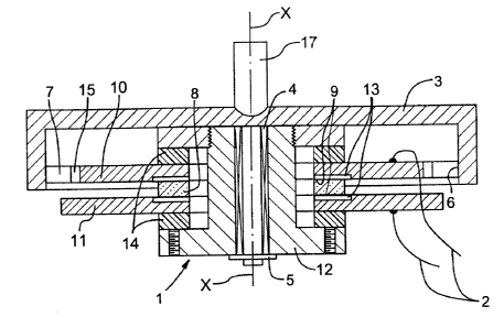
Fig. 1 is a sectional side view of a piezoelectric motor according to a first
embodiment of the invention, showing plates pressed against the
piezoelectric element's surface,
Fig. 2 is a sectional side view of a piezoelectric motor according to a second
embodiment of the invention, showing pushers anchored on the rotor in the
shape of a barrel,
Fig. 3a is a schematic diagram of a motor according to the invention, showing
pushers anchored on the plate's internal cylindrical surface,
Fig. 3b is a schematic diagram of a motor according to the invention, showing
pushers set with one end against the plate's internal cylindrical surface,
Fig. 3c is a schematic diagram of a motor according to the invention, showing
L-
shaped pushers,
-6-
CA 02315013 2000-08-03
Fig. 4a is a schematic diagram of a piezoelectric element according to the
invention,
showing two plates pressed against the element with pushers anchored on
the plates,
Fig. 4b is a schematic diagram of a piezoelectric element with two plates
pressed
against it,
Fig. 5a shows an alternative way of anchoring a pusher on the plate,
Fig. 5b shows an alternative way of anchoring a plurality of pushers together
on the
plate,
Fig. 6a shows a disk with deep slots,
Fig. 6b shows a disk with medium depth slots,
Fig. 6c shows a disc with shallow slots,
Fig. 7a shows a piezoelectric element with electrodes on the flat surfaces of
the
element,
Fig. 7b shows a piezoelectric element with electrodes on the cylindrical
surfaces of
the element, and
Fig. 8 shows a sectional side view of a third embodiment of a piezoelectric
motor
according to the invention, showing a motor of the so called converted type.
DETAILED DESCRIPTION OF THE INVENTION
The piezoelectric motor contains a stator 1 (as shown in Fig. 1 ) with leads 2
for
connecting to an AC voltage source (not shown). The stator is the stationary
part of the
piezoelectric motor relative to the unit (not shown) where it is mounted. A
rotor 3 of the
piezoelectric motor is mounted on the stator 1 so the rotor can rotate in a
bearing 4 and
-7-
CA 02315013 2000-08-03
is fixed to avoid axial motion by a detachable joint 5, for example a' lock
washer. The
rotor is fixedly attached to an output shaft 17, which rotates together with
the rotor and
thus provides the rotational motion generated by the piezoelectric motor. The
longitudinal axis of the output shaft is designated X in Fig. 1.
The stator 1 and the rotor 3 are in mechanical contact with one another on a
cylindrical
friction interaction surface 6 by means of curved, elastic and longitudinally
elongated
pusher plates 7, which are positioned at an angle to the friction surface 6.
The pusher
plates are preferably substantially rectangular and as a rule have a uniform
thickness,
to facilitate the manufacturing process. The pusher plates 7 are contacting
the friction
surface 6. The stator 1 includes a ring piezoelectric element 8 with
electrodes made of
a piezoelectric material. This also implies that, alternatively, the motor may
be rigidly
anchored on the rotor, which will mean that, in essence, the stator and the
rotor will
exchange places, and the above piezoelectric element 8, just as the rotor's
other parts,
will become part of the rotor.
The piezoelectric element 8 is located between a first ring plate 10, on which
the
pusher plates 7 are anchored with an anchor ring 15, and a second ring plate
11, acting
as a counterpoise in order to prevent excitation of curve oscillations in the
piezoelectric
element with the first plate 10, and thus avoid losses in mechanical energy.
The first
ring plate 10 and the second ring plate 11 are substantially parallel to each
other.
The first ring plate 10 and the second ring plate 11 are, furthermore, pressed
against
the surface of the piezoelectric element 8 by a clamp 12, for example a steel
bolt with
a nut.
In order to protect the piezoelectric element from being damaged when the nut
is
tightened, thin gaskets 13 made of a sound-conductive material, for instance
aluminum,
are installed between the piezoelectric element 8 and the first ring plate 10
and the
second ring plate 11, respectively.
_g_
CA 02315013 2000-08-03
A distinctive feature of the design of the motor shown in Fig. 1 is that
longitudinal radial
oscillations are excited in the piezoelectric element from the source (not
shown) when
the electrodes 9 are connected to the source by means of the leads 2,
virtually without
any losses. This is due to the presence of the counterpoise second ring plate
11. The
piezoelectric element 8, the first ring plate 10 and the second ring plate 11
form a
single oscillatory system of radial oscillations with a resonance frequency
determined
by the size of not only the piezoelectric element but also the ring plates 10
and 11,
respectively.
To prevent that a part of the acoustic energy branches into the clamp, the
clamp is
sound-insulated from the first ring plate 10 and the second ring plate 11 by
means of
soundproofing devices 14. The soundproofing devices are preferably made in the
form
of rubber washers separated from the bolt head and the nut by steel washers.
In the design of the engine shown in Fig. 1, the pusher plates 7 are anchored
at one
end on the exterior of the first ring plate 10. The other end of the pusher
plates 7 is
supported by the cylindrical friction surface 6 of the rotor 3, with the rotor
being in the
form of a barrel enclosed by the pusher plates 7.
In the design of the engine shown in Fig. 2, the rotor 3 also has a part in
the form of a
barrel, and the pusher plates 7 are at one end anchored on the walls of the
barrel part
of the rotor, and are supported at the other end by the cylindrical surface of
the first ring
plate 10, which is the friction interaction surface 6 in this embodiment. The
diameter of
the friction interface surface is approximately 2 pusher plate lengths shorter
than the
diameter of the cylindrical surface of friction interaction of the motor shown
in Fig. 1
and, consequently, the rotational speed of the motor with pusher plates
positioned on
the rotor (Fig. 2) is higher than that of the motor with pusher plates
anchored on the
plate (Fig. 1 ). Still shorter is the rotor diameter of the motor with pushers
positioned on
the rotor 3 and supported by the interior cylindrical surface of the first
ring plate 10,
which is illustrated in Fig. 3a.
_g_
CA 02315013 2000-08-03
Maximum rotational speed is reached in the motor where the pushers are
anchored on
the interior cylindrical surface of the plate 10 (Fig. 3b). The rotor 3,
enclosed by the
pusher plates, is made in the shape of a cylinder.
Using motors as described above, with different options for positioning and
anchoring
pusher plates, rotation engines can be designed having rotation speeds
starting from
several rotations per minute and up to 1000 rpm and having starting torques
from 20
Hm to 0.01 Hm.
For low-power, high-rotation motors with a small inner orifice of the
piezoelectric
element, pusher plates are preferably made to in an L-shape and anchored on
the
exterior cylindrical surface of the first ring plate 10, as shown in Fig. 3c.
An essential distinctive feature of piezoelectric motors with the pusher
plates 7
anchored on the first ring plate 10 is the fact that the external diameter of
the
counterpoise second ring plate 11 is larger for the embodiment where the rotor
3 is
enclosing the pusher plates (Fig. 1 ), than the diameter of the first ring
plate 10 with
anchored pusher plates.
The larger the number of pusher plates, the larger the difference in the
diameters
should be. The required ratio of the plate diameters is selected
experimentally by the
following method.
A rotation system is assembled, where the counterpoise second ring plate is
replaced
by a plate with pusher plates, as shown in Fig. 4a. The resonance frequency of
the
oscillation mode which is chosen to be the working one (e.g. Mode 1 of radial
oscillations, i.e. 19' order resonance frequency) is measured by known
methods. Then,
a second rotation system is assembled out of counterpoise second ring plates
(Fig. 4b).
By changing the external diameter of the counterpoise ring plate, it is
possible to
achieve equal resonance frequencies of the working oscillation mode.
-10-
CA 02315013 2000-08-03
In a similar manner, if the pusher plates are anchored on the interior
cylindrical surface
of the first ring plate 10 (Fig. 2), then, in order to match resonance
frequencies, it will
necessary to increase the external diameter andlor reduce the internal
diameter of the
counterpoise second ring plate 11, using the method described above.
Normally, longitudinal radial oscillation Mode 1 is selected as the working
mode.
However, in case of powerful motors, radial oscillation Mode 1 can be in the
acoustical
frequency range. In such an event, the working mode is selected as
longitudinal
resonance oscillation mode M, depending on ring width. This design is
illustrated in
Figs. 3a and 3b.
The engine's parameters are largely determined by the selected area of the
surface of
contact between the piezoelectric element 8 and the first ring plate 10 and
the second
ring plate 11. In the simplest case, the whole flat surface of the
piezoelectric element
is used for the acoustic contact between the piezoelectric element and the
first ring
plate and the second ring plate. Energy losses due to friction in this event
are maximal,
since the oscillation rates of the points of contact between the plates and
the
piezoelectric element are unequal. In order to avoid such losses, the
soundproofing
gasket 13 is advantageously made in the form of a narrow ring and positioned
at the
edges of the piezoelectric element (Figs. 2 and 3c) or in its center,
depending on the
oscillation mode.
The motor's parameters depend largely on the choice of soundproofing devices
14, as
well. In the event that there are no rigid requirements to the motor's height,
the
soundproofing devices 14 are preferably made in the form of thin-walled
cylinders, as
shown in Fig. 2.
In the event that the pusher plates 7 are anchored at one end on the first
ring plate 10,
the method of anchoring the pushers becomes vitally important for the motor's
parameters. In certain technological approaches, the pushers are anchored in
slots
(recesses) 18 (see Figs. 6A to 6C), arranged at the periphery of the first
ring plate, by
means of glue compounds or lead-and-tin solders, for example. A distinctive
feature of
-11-
CA 02315013 2000-08-03
the technological approach discussed here is that the pusher plates 7 are at
one end
anchored in the slots 18 of the first ring plate 10 by means of drafting the
slot, up to its
closing with additional stress acting on the pusher plate from the direction
of the slot
walls (Figs. 5a and 5b), forming plate holding wells 19.
According to this method, one or more pusher plates 7 can be anchored in one
slot 18
as illustrated by Fig. 5b. Three pusher plates are shown arranged in one slot,
but any
desirable number may be used, for example 2, 4, 5, 6, 7, 8, 9, 10 etc.
A resonator 10,11 with a deep slot 18 (Fig. 6a) has virtually no radial
oscillation mode.
A resonator with a medium-deep slot 18 (Fig. 6b) has a number of resonances,
radial
oscillation mode among them. In a resonator with a shallow slot 18 (Fig. 6c),
the radial
oscillation mode has two nearly similar resonance frequencies, each of which
draws
energy away from the adjacent oscillation mode. Filling the slots with a
compound or
solder does nothing to eliminate this phenomenon. Anchoring the pushers by
drafting
the slot, forming plate holding wells 19, leads to the matching of resonance
frequencies, which manifests itself in the motor by a decrease in the phase
shift
between the current and the voltage at the motor's inlet.
The excitation of longitudinal elastic vibrations (waves) in the first ring
plate 10 and the
second ring plate 11 becomes possible due to the fact that the piezoelectric
element
has the form of a ring, preferably made of a polarized piezoelectric ceramic
material
with electrodes on its on sides. In a first embodiment of the piezoelectric
element
shown in Fig. 7a, the electrodes 9 are applied (e.g. by spraying) onto the
piezoelectric
element's flat surfaces. In the second embodiment shown in Fig. 7b, the
electrodes 9
are applied onto the cylindrical surfaces of the piezoelectric element 8. For
both of the
above embodiments, the polarization of the piezoelectric ceramic is achieved
by high
voltages applied to the electrodes. The direction of polarization is shown on
the figures
by arrows, and matches the direction of the polarizing voltage.
An important characteristic of a motor is its torque (resource). A motor's
torque
(resource) largely depends on the material used for the friction surface and
the portion
-12-
CA 02315013 2000-08-03
of the pusher plate which comes in contactwith the friction surface. Steel is
the material
used in relatively inexpensive engines for the friction surface and the pusher
plates. In
order to increase the resource, a coating of chrome or another super-hard
material is
applied to the steel in the zone of mechanical contact. Sometimes,
formaldehyde resin
based materials or aluminum oxide ceramics are selected as the contact
materials.
The starting torque of a piezoelectric motor increases proportionally to the
increase in
the number of pusher plates used. The known methods of anchoring the pusher
plates
on the piezoelectric element do not guarantee a high reliability of the motor,
because
during fixation of each new pusher plate there is a possibility of the
piezoelectric
element or its electrodes collapsing, cracking or otherwise getting damaged.
In the
technological approach described here, on the other hand, the motor's
reliability and
torque (resource) increase with the increase of the number of pushers, and as
far as
the influence of the one pusher plate in overall mass of the pusher plates it
insignificantly affects the motor's parameters. Furthermore, the pusher plates
themselves are arranged outside of the piezoelectric element and its
electrodes.
In motors with pusher plates 7 anchored on a steel rotor, where a
piezoelectric element
8 having electrodes on the cylindrical surfaces is used, the number of pusher
plates
can be doubled by using the cylindrical surface of the second ring plate 11 as
the
second surface of friction interaction (Fig. 2). As has been noted before, the
rotor and
stator can switch places. This sometimes allows a notable simplification of
the motor's
design (Fig. 8), since, when the once mobile rotor 3 becomes a stator, it acts
as the
protective housing a motor is usually supplied with (see, for instance, the
motor shown
in Fig. 2). Such motors are called converted in this text.
In such an event, one of the leads 2 is connected to the motor's stator, and
the other
lead, via a sliding contact and metal second ring plate 11, to the electrode 9
of the
piezoelectric element 8. The claimed piezoelectric motor operates as follows.
The
supply voltage from a power source having a frequency equal or close to one
resonance frequency of longitudinal radial vibration of the system containing
the
piezoelectric element 8, the first ring plate 10, the second ring plate 11 and
the pusher
-13-
CA 02315013 2000-08-03
plates 7, is connected to the piezoelectric element 8 through the leads 2 and
electrodes
9 (see Fig. 1 ). The piezoelectric element will compress and expand under the
applied
A.C. voltage, generating a longitudinal traveling wave of the
expansionlcompression
deformation. This wave does not develop further through the soundproofing
gasket 13
and penetrates the first ring plates 10 the second ring plate 11 and,
consequently, the
pusher plates 7.
Reflected from the external cylindrical surfaces of the plates, the waves
repeatedly
return to the piezoelectric element 8, etc., and, reflected from the
boundaries, form a
standing wave of longitudinal radial oscillations, whose amplitude is Q times
larger than
the amplitude of the traveling wave (Q is the quality of the oscillation
system).
The mechanical oscillations amplified by the resonance arrive at the pusher
plates 7
and compel the pusher plates to oscillate longitudinally. The pusher plates,
slanted
towards the cylindrical surface and set against it, move both longitudinally
and
transversely. The transverse wave thus generated, phase shifted in relation to
the
longitudinal oscillation wave, forces the pusher plate ends to move along an
elliptical
trajectory, while, every time the pusher plates enter into engagement with the
rotor
(along the surface of friction engagement), they push the rotor 3 (Fig. 1 ),
thus relaying
to it the unidirectional motion impulse.
Oscillations of the first ring plate 10, the second ring plate 11 and the
piezoelectric
element 8 generate repulsion forces between them. The clamp 12 provides a
clamping
force which exceeds the repulsion forces. The damage hazard to the
piezoelectric
element is significantly reduced by the fact that the piezoelectric element is
enclosed
on either side. This is the reason the maximum pulse power of the motors
described
here is several times higher than that of the known motors, where the maximum
pulse
power is limited by the damage hazard to the piezoelectric element.
Using plain bearings 4, for example made out of porous oil-saturated bronze,
guarantees the motor's long life, with the rotor 3 rotating in relation to the
stator 1, while
the lock washer 5 prevents axial motion of the rotor 3 in relation to the
stator 1.
-14-
CA 02315013 2000-08-03
The functioning of the reverse motor shown in Fig. 8 is based upon a principle
similar
to the one described above, with the only difference being that electric
energy is
supplied to the piezoelectric element 8 from the leads 2 via the pusher plates
7 and a
sliding contact 16. The moment of inertia of the rotor 3 of a converted engine
is much
lower than that of motors with a stationary piezoelectric element (see e.g.
Fig. 1 ). That
is why this motor has a higher quality as a positioner. Elastic radial
oscillations of the
external cylindrical surface of the first ring plate 10 and the second ring
plate 11 (Fig.
2) cause the ends of the pusher plates 7 anchored on the rotor 3 to experience
longitudinal and transverse displacements, as well. As a result, longitudinal
and
transverse (flexural) waves are generated in the pusher plates, which, being
unbound
acoustically and phase shifted, compel the pusher plate ends to move along an
elliptical trajectory. Coming into contact with the cylindrical surface of the
first ring plate
10 and the second ring plate 11, the pushers 7 pushing off, cause the rotor 3
to rotate
(Fig. 2).
The motor described here uses a piezoelectric element with electrodes on
cylindrical
surfaces (Fig. 7b). If a piezoelectric element with electrodes is used on flat
surfaces
(Fig. 7a), it will be short-circuited by the pusher plates 7. The use in the
motor of the
clamp 12 in the form of a flared-out tube is but a technological peculiarity
not affecting
the motor's functioning in any way. Installing L-shaped pusher plates in each
of the n-
plate slots (Fig. 3c) has no serious effect, either. As for the flaring out of
the pusher
plates (Figs. 5a to 6c), this, as has been noted before, renders the
oscillation system
mono-frequency, thus reducing the power angle.
A motor with a large diameter piezoelectric element used for achieving
relatively high
power values has a certain essential distinction. In such motors, the first
ring plate 10
and the second ring plate 11 excite the longitudinal resonance of oscillation
Mode 1 in
the width direction of the plates. Placing the rotor 3 (Fig. 3 a, b, c) inside
the pusher
plates, allows using aluminum oxide based mineral ceramic materials for the
rotor
manufacture, without a notable increase in the motor's cost.
-15-
CA 02315013 2000-08-03
The results of tests performed on a wide class of motor designs in regard to
the
technological approaches discussed above, have confirmed the expectations that
the
motors described here will have a number of advantages over the previously
known
motors. Those advantages include, above all, high reliability and convenience
of use
under the conditions of primitive automation.
It will be appreciated that the above description relates to the preferred
embodiments
by way of example only. Many variations on the invention will be obvious to
those
knowledgeable in the field, and such obvious variations are within the scope
of the
invention as described and claimed, whether or not expressly described.
-16-