Note: Descriptions are shown in the official language in which they were submitted.
CA 02315398 2000-06-15
- WO 99/32417 . PCT/AU98/01049
DFNSE REFRACTORIES WITH IMPROVED THERMAL SHOCK RESISTANCE
The present invention relates to a refractory material and
to a method of manufacturing the refractory. material.
A simple definition of a refractory material is one which
resists the effects of high temperatures. Commonly, the
term refractory material is applied to relatively low cost
products that are used in many industrial processes,
typically operating at high temperatures, to contain
corrosive materials, such as molten metal and slaps. As
such refractories are an important class of materials.
The following factors are relevant to the design of
refractory materials:
chemical compatibility;
thermal shocks
constraints on start-up;
operating conditions;
slag penetration;
hot strength
creep resistance; and
cost.
Many ceramics materials have properties in common with
refractory materials. gor example, ceramic materials are
characterised by excellent chemical stability, high
hardness and a brittle nature. In comparison with
refractory materials, typically ceramic materials have poor
thermal shock resistance. The combination of poor thermal
shock resistance and high cost limits the use of ceramic
'materials in refractory applications.
There are two options to minimise the effects of thermal
shock. The first is to avoid the initiation of cracks and
CA 02315398 2000-06-15
WO 99/32417 PCT/AU9$/01049
- a -
the second is to avoid catastrophic crack propagation.
Thermal Shock Damage Resistance Parameters (R), a measure
of a material s resistance to the above types of failure,
were proposed by Hasaelman (see Introduction to Ceramics,
Ringery a~° edition 1976 pp 825-30). The physical
properties required to compute Thermal Shock Damage
Resistance Parameters are thermal conductivity k, thermal
expansion coefficient a. YouaQ~s Modulus E, effective
fracture energy y,==, and strength (MOR) a. Specifically,
the Thermal Shock Damage Resistance Parameters R' and R
can be expressed as:
kQ
R' _ '-' ( 1 )
Ea
and
Ey
""= Q~' (a)
where R' is the parameter for the resistance to crack
initiation and R " " is the parameter for the resistance to
crack propagation.
The material characteristics for inhibiting crack formation
are high strength with respect to elastic modulus. The
requirements for minimising the extent of crack propagation
are a high product of work of fracture and elastic modulus
with respect to strength. Thus, the design requirements for
a material for inhibiting crack formation and crack
propagation are different.
=t is known that resistance to catastrophic failure, which
is required in refractory applications, can be improved by
the introduction of enough cracks of sufficiently large
size so that crack propagation takes place semi-statically.
CA 02315398 2000-06-15
- ~ WO 99/32417 . PCT/AU98/01049
- 3 -
=t is also known that, alternatively, resistance to
catastrophic failure can be achieved by the introduction of
microstructural inhomoQenieties in any form Which serve as
stress concentrators in the material. In this way, cracks
will form locally, but catastrophic failure.is avoided as a
result of the small average stress in the material.
Conventional refractory materials are designed for chemical
stability, thermal shock resistance, and cost. This is
achieved through a con~romise between reducing the
effective surface area for attack and increasing resistance
to crack propagation. Typically, a conventional refractory
material has an open structure With between 15 and 20%
porosity. The open structure allows rapid penetration of
slaQs and gases but inhibits crack propagation. A schematic
representation is shown in Fig. 1.
The shortcomings of this compromise approach to design were
recognised by the late Ronald C. Garvie. He proposed that a
dense thermal shock resistant material would offer superior
performance to a conventional refractory material. To
achieve this goal he introduced micro-cracks into the
microstructure. This increased the work of fracture for the
material by promoting crack branching. The end result was a
dense material with the chemical stability of an advanced
ceramic and the thermal shock resistance of a porous
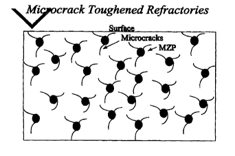
refractory. This micro-crack toughened coawposite material
is disclosed in US patents 5,296,420 and 5,334,563 of
Garvie. A schematic representation of the composite
refractory material is shown in Fig. 2.
The essential features of the composite material disclosed
in US Patent 5,334,563 are that the material have less than
12% porosity and comprise:
a matrix of alumiaa, with 5 to 90% by volume of
the alumina grains having a diameter in the range
CA 02315398 2000-06-15
- - WO 99/32417 - PCTIAU98I01049
- 4 -
of 15 to 8O microns;
particles of monoclinic zirconia dispersed is the
matrix, each dispersed particle comprising an
agglomerate of microcrystals which;
(a) are strongly bonded together;
(b) exhibit a strong thermal expansion
anisotropy; and
(c) a size such that cracks do not form
spontaneously within the agglomerates after
cooling from high temperatures in the range
of 1600°C; and
the alumiaa and the monoclinic zirconia being
chemically inert with respect to each other
within the temperatures used in practice.
The Garvie US Patent also discloses a number of other
combinations, such as: mullite as the matrix and zirconia
as the dispersed material; silicon nitride as the matrix
and boron nitride as the dispersed material; barium
titanate as the matrix and zirconia as the dispersed
material; silicon carbide as the matrix and boron nitride
as the dispersed material; alumiaa as the matrix and
aluminium titanate as the dispersed material; spinal as the
matrix and zirconia as the dispersed material; and
fosterite as the matrix and zirconia as the dispersed
material.
The basis of the Garvie US Patent is the addition of a
dispersed second phase in a continuous dense matrix with
very particular inter-dependence of the respective thermal
expansion coefficients of the phases. Specifically, the
use of specific grades of monoclinic zirconia as the
CA 02315398 2000-06-15
WO 99/32417 PCT/AU98I01049
- 5 -
8isperaed phase produced as enhanced
dilatatioaal/coatractional mismatch is a number of matrices
such as alumina or zircon. Aa optimised composition, with
respect to thermal shock damage resistance (measured by
retained strength) was determined empirically by Garvie to
be 8% by weight of zirconia in alumina and 10% by weight is
zircon.
Extensive chemical attack of ceramic matrix materials, such
as zircon and alumina, limits the use of such ceramic
composites in many corrosive industrial applications. These
include applications where the ceramic composite is in
contact with slaps used in iron and steel making
operations.
A further significant problem is the prohibitive cost of
production of the composite ceramic materials oa an
industrially realistic scale.
It is known that reaction sintering of zircon mixtures can
result is the formation of oxide zirconia dispersions (see
for example OS Patent 2842447 by Schlotzhauer and wood and
Cambier; Baudin de La Lastra, Dilate and Leriche Brit.
Ceram. Soc. Trans. and J. 83 pp 196-200, 1984). As
discussed by Cambier et. al. the use of this technique is
useful in the manufacture of zirconia is a mullite or
alumina mullite matrix. These materials are characterised
by high strength with MOR values that can reach 400 to
5001~Pa. =n addition, these materials are typically
characterised by pores around the zirconia particles as a
consequence of the process. That is, the original zircon
particles lose silica to the surrounding matrix. There is a
volume decrease reported to be about 20% for the zircon
particles converted into zirconia particles. This results
in the formation of pores associated with the zirconia
grains. Furthermore, Schlotzhauer and Mood (col. 3, lines
11-20 of the US Patent) indicate that the high corrosion
CA 02315398 2000-06-15
- WO 99/32417 - PCT1AU98/01049
- 6 -
resistance of the final products is a consequence of the
lack of cracking associated with the inversion of the
zircoaia as it is heated or cooled through 1000~C. The
presence of such pores would accommodate the volume
expansion of zirconia associated with the inversion of the
zirconia on cooling without the generation of stresses or
strains.
US Patent 4298385 of Claussen and Steeb discloses a method
for producing bodies having high fracture toughness and
"substantially equal" mechanical strength. This is achieved
by the addition of from 4 to 25 volume % zirconia grains
("embedment material") with a diameter from 0.3 to 1.25 lun
in as anisotropic ceramic matrix, such as alumiaa. The
improvement is the properties of the fabricated products
resulted, by way of exaa~le in the case of alumiaa with
unstabilised zirconia, from the production of extremely
fine micro-fissures and a high fissure density in the
products. This was reported to significantly increase the
toughness, thermal shock resistance and impact strength as
compared to products prepared without the zirconia
addition. In addition, it was found that it was preferable
to disperse the zirconia within agglomerates of zirconia
and matrix phase with a size of 2 to 15 um containing from
4 to 25 volume % (preferably 8 to 25 volume %) of the phase
(Col 2, lines 9 to 54). For alumina this is ectuivalent to
5.8 to 32.8 wt% and preferably 11.3 to 32.8wt%.
Furthermore, it is also taught that the use of large
embedment material is to be avoided, as the strength is
considerably reduced (Col 4, lines 43 to 46). From the
results presented in Figure 1 of the US patent it is
clearly seen that increasing the particle size embedment
materials from 0.3~m to 1.25pm required an increase in the
amount of the embedmeat material from 10 vol% to 15 vol%
(14 to 20.6 wt%) and this indicates the benefits of the
smaller zirconia grain size. The examyles disclose the use
of high vol% of the embedment phase. For example in Fig. 6 1,,
CA 02315398 2000-06-15
- - WO 99/32417 . PGTIAU98/01049
_ 7 _
the vol% ranges from 15 to 25 vol%. It is further reported
that such materials are especially suited to high
tea~erature Qas turbine elements.
US Patent 4,804,644 of Aaseau, Lawson and Slasor also
discloses a material which includes dispersion of zirconia
is a matrix, in this case as 0'-sialon matrix. 0'-sialon is
a solid solution based on silicon oxynitride (Si,N,o) where
there is substitution of Al sad 0 for Si and N
respectively. The OS Patent discloses a number of methods
for the preparation of such materials. However, for
materials produced according to the methods the zircoaia is
is the tetragonal form. It is stated that improvements in
properties would result from the transformation of meta-
stable tetragonal zirconia to the monoclinic form in
response to a tensile stress typically caused by an
advancing crack tip. The transformation results is the
formation of compressive stresses that tend to close the
cracks. =adeed from example 18 of the US Patent. the
zircoaia is reported to be is the tetragonal form at room
ten~erature. For the zircoaia to be effective the size of
the particles must remain small to prevent spontaneous
transformation on cooling. There is ao report of the
physical properties such as strength aa8 thermal shock
resistance of such bodies formed.
An object of the present invention is to provide a
refractory material with enhanced corrosion, erosion sad
thermal shock resistance which alleviates the disadvantages
of the kaov~ra refractory materials discussed above.
Accordir~ to one aspect of the present invention there is
provided a dense refractory material which includes a matrix
and a micro-crack initiating single czystal phase formed from
fused zircoaia dispersed in the matrix.
The tezm "dense" is understood herein to mean that the
CA 02315398 2000-06-15
WO 99/32417 - PCT/AU98/01049
- 8 -
refractory material has limited open porosity, typically less
than 5% by volume.
According to another aspect of the present invention there is
provided a dense refractory material which includes a spinal
matrix.
The spinal group of materials is understood herein to mean
materials that are described by the general formula:
ABsO,
where A'' is typically is either singly or in combination
Mg, Fe, Zn and Mn and B'' is typically either singly or in
combination Al, Fe, Cr and Ma.
Examples of spinals are magnesium aluminium oxide MQA1~0~,
magnetite Fe,O~, and chromite FeCr,O~ . An exaa4ple of a
"mixed" spinal is MQ(Al,Fe)s0~.
The spinal group of materials have a cubic crystal
structure and, therefore, are isotropic. As a consequence,
the spinal microstructure is relatively stress-free.
Furthermore. the spinal group of materials is relatively
stable at high temperatures and while maintained at
temperature.
The spinal may include one or more additional elements. The
additional elements may include Li, Mg, Ca, Ti, 1~, Fe, Co,
Ni, Cu, Zn, sr and sa, for divalent cations and A1. Cr, Fe,
and Mn as the trivalent cations. In addition, spinal phases
can exist over a range of coa~ositions with respect to the
ratio of the divalent to trivalent cations.
The selection of the additional elements may depend on a
Wide range of factors. By way of example, one factor is
CA 02315398 2000-06-15
- - WO 99/32417 - PCT/AU98/01049
- 9 -
the environment in which the refractory material will be
used. Specifically, in situations where the refractory
material will be in contact with molten slag in metal
smelting operations, the additional elements may be
S selected to optimise the chemical stability~of the
refractory materials with respect to the slag. By way of
further example, another factor is to include additional
elements to assist in the manufacture of the refractory
material as a dense refractory material.
A further advantage of spinals is that they can exist over
a range of coagposition without a change in phase. For
example, magnesium aluminate spinal can be magnesium rich,
stoichiometric (Mg to Al ratio of 1:2) or aluminium rich.
This allows the loss of an element from the crystal lattice
without decomposition to form a new phase or compound.
Typically, the formation of new phases can result in
physical disruption of the refractory body or the formation
of less refractory phases. The ability of the spinal to
adapt to the environment without a change is phase enhances
the stability of the products.
=t is known that spinals, such as magnesium aluminium oxide
MgAl~O~ and chromite FeCr=O~ spinals, have excellent
corrosion resistance to slaps in metal smelting operations.
However, typically, the spinals are coarse and are use8 as
grits or aggregate in refractory bodies for many metal
making and cement making operations and not as the matrix
of a dense refractory material. Moreover, the refractories
that incorporate these spinals are in the form of
traditional refractoriea that are characterised by open
porosity and are not dense refractory materials.
Furthermore, whilst the C3arvie US patents propose the use of
spinals in a matrix of a micro-crack toughened refractory
material, the disclosure is speculative sad not supported by
examples.
CA 02315398 2000-06-15
WO 99/32417 - PCT/AU98/01049
- 10 -
It is preferred that the refractory material further
comprises a micro-crack iaitiatin~ phase dispersed in the
matrix.
=t is preferred that the micro-crack initiating phase be no
more than 15% by volume of the material.
It is preferred particularly that the micro-crack initiatiz~gr
phase be no more than 10% by volume of the material.
It is preferred that the spinal matrix be at least 80% by
volume of the material.
=t is preferred particularly that the spinal matrix be at
least 90% by volume of the material.
=t is preferred that the micro-crack initiating phase
comprises a dispersion of single crystals.
It is preferred that the micro-crack iaitiatiaQ phase be
formed from zirconia.
It is preferred that the zirconia have a particle size in the
rsaQe of 5 to 50E,tm.
It is preferred that the zirconia have a particle size in the
range of 10 to 20~Im.
=t is preferred particularly that the zirconia be fused
zirconia.
The_micro-crack iaitiatinQ phase may be formed from any other
suitable material, such as boron nitride and silicon carbide.
=t is preferred that the spinal be manufactured from law cost
precursors.
CA 02315398 2000-06-15
WO 99/32417 - PGT/AU98101049
- 11 -
According to another aspect of the present invention there is
provided a dense refractory material which includes a
spinal matrix and a micro-crack initiating phase dispersed
in the matrix.
According to another aspect of the present invention there is
also provided a method of manufacturing a dense refractory
material product which includes the steps of:
(i) mixing precursor oxides for a spinal
material;
(ii) calcining the mixture to form the spinal
material;
(iii)forming the spinal material into a green form
of the product; arid
(iv) firing the green form of the product to
produce the final form of the product.
It is preferred that the method further includes the step of
mixing the spinal material produced in step (ii) with an
additive, such as zirconia. selected to form a micro-crack
initiating phase dispersed in the fired product.
According to the present invention, the spinal material is
formed by reaction of the precursor oxides. This is typically
carried out in the temperature range of 800°C to 1600°C and
preferably in the range of 1000°C to 1400°C for dwell times
at temperature ranging up to at least 10 hours. Longer times
are generally preferred for lower calcination temperatures
and shorter times for temperatures is the upper reaches of
the range. D~rell times of 1 hour or less are possible for
higher temperatures in the range.
CA 02315398 2000-06-15
- WO 99132417 _ PCT/AU98I01049
- 12 -
Typically, the spinal material formed is they milled (if
necessary) to form a finely divided powder suitable for
deasification in the secondary heat treatment of step (iv).
Typically, the average particle size should be less than ZO
E,Im, preferably less than 5~"tm and more preferably less than
2~,I,m.
Typically, the additive which form8 the dispersed phase is
then added to the spinal powder.
Typically, the spinal ponder and the additive are then
moulded or formed into the desired shape is a green form in
step (iii). This can be done with and without the use of
additives to increase the plasticity of the powder
facilitating forming into the desired "green" shapes.
The green shape is then heated to effect densification is the
firing step (iv). This is typically carried out in the
temperature range of 1000°C to 1800°C and preferably in the
range of 1400°C to 1600°C for darell times at temperature
ranging up to at least 10 hours. Longer times are generally
preferred for lower secondary heating tea~eratures and
shorter times for temperatures is the upper reaches of the
rsage. Dwell times of 1 hour or less are possible for higher
tem~peratur~s is the range. Temperatures can also be reduced
by use of sintering assists that can be incorporated into the
structure of the spinal. However, it is pr~farable that the
firing temperature used in the manufacture be at least as
high as the expected operating temperature where the
refractory is to be used.
Sintering aids may be used to promote densification of the
refractory material. These aids can foszn liquids that result
in enhanced diffusion rates thereby increasing the
densificatioa rate. Where these additives exist as secondary
phases in the final microstructure they can exert a
deleterious effect on the performance of products. It is well
CA 02315398 2000-06-15
- , WO 99/32417 . PCT/AU98/01049
- 13 -
known that the presence of silica-based glasses and calcium-
containiaQ phases can lead a marked decrease in the high
temperature properties of alumiaa based refractories.
Appropriate sintering aids may be used to promote
deasificatioa at lower temperatures without a loss of
performance. The firing cycle of refractory materials can
represent a substantial proportion of the cost to manufacture
products. Reducing the firing temperature can result is a
lower cost to manufacture products. =n addition, it is
postulated that improved chemical stability is obtained by
using a matrix material that contains the main elemeata of
the slag in a solid solution within the crystal structure of
the matrix phase or where stable phases are produced as a
result of the interaction of elements in the slag with the
matrix.
The dense refractory material of the present invention
contains micro-cracks in the microstructure after
fabrication. These micro-cracks are characterised by
emanating from the dispersed phase (typically formed by
zircoaia additions) and extending over several grain
diameters is the microstructure. Typically the grain size
is the order of greater thaw IO yam.
As stated above, the spinal group of materials is defined
by the general formula A8s0~ where A'' is typically is
either singly or is combination big, Fs, Za and Ma and B3'
is typically either singly or is combination Al, ge, Cr and
»n. The spinal may include one or more additional elements.
The additional elements may include Li, Mg, Ca, Ti, Ma, P'e,
Co, Ni, Cu, Zn, Sr and Ba, for divalent cations and Al, Cr,
ge, and Ma as the trivalent catioas. In addition, spinal
phases can exist over a range of compositions with respect
to the ratio of the divalent to trivalent cations.
As indicated above, zircoaia is the preferred additive to
CA 02315398 2000-06-15
- - WO 99/32417 - PCT/AU98I01049
- 14 -
for the dispersed phase. It is well lmowa that certain
8opants can stabilise the high te~oo~erature crystallographic
forms of zirconia at room temperature. Typically, dopants
include magnesia, ceria, yttria and calcia. For the case
of spinals that tyyically include elements that can
stabilise the high temperature forms of zircoaia it is
surprising that products formed according to the present
invention do not contain zirconia particles that are
stabilised. Such stabilisation would render the micro-
cracking mechanism responsible for the improvement in
thermal shock inoperative. From thermodynamic
considerations it is believed likely that the dopaats for
zirconia would be partitioned between the zircoaia and the
matrix. With the exception of certain instances is the
finer fractions, this it not observed. Furthermore it is
believed that large particle size and hence uareactivity of
the zirconia particles is responsible in part or whole for
the observed behaviour. This indicates the requirement for
large uareactive zirconia particles. Another advantage of
such particles is the relative low cost of large uareactive
powders and grits as compared to finely divided and
reactive powders. Such fine fractions maybe advantageous
for other reasons but they do not contribute to the
improvement in thermal shock behaviour for refractory
bodies as described by the current invention.
The present invention overcomn~es th~a problems of obtaia3ag low
cost refractory materials with high erosion and corrosion
stability.
Ia relation to the prior art discussed above, the process
disclosed by Schlotzhauer and Wood aa8 Cambier is clearly
different to that of the present invention. =a the present
invention, cracks are deliberately created by the inclusion
of the zircoaia (or other dispersed micro-crack initiating
phase). That is, the stresses and strains associated with
the inclusion of zirconia into the matrix can not be
CA 02315398 2000-06-15
WO 99/32417 PCTIAU98I01049 -
- 15 -
accommodated by the matrix and result in the formation of
cracks.
A feature of the present invention is the tolerance to
S impurities and the fact that low cost refractory grade
precursors can be used. This allows the use of low coat
refractory precursors. It is speculated that the finer
fractions of the zircoaia materials used are able to react
with impurities to produce more refractory phases.
Ia addition, the body disclosed by Claussen sad Steeb is
substantively different to that is the present invention.
The Claussen and Steeb body retains high fracture strength
and fracture toughaeas. This is achieved by the requirement
for the use of a large vol% of micron and preferably sub-
microa zircoaia material. The materials produced according
to the teachiaga of the present invention are for
refractory type applications. A requirement for this type
of material is relatively low cost. This typically means
below US$5,000 per tonne for the finished product. Such a
final price requires the use of inexpensive rsw materials.
Sub-micros zirconia powders are expensive. At the current
prices for such zirconia powders at the levels required
according to the teachings of Claussen sad Steeb would
equal or in some cases exceed the price of the final
product produced according to the present invention. In the
present invention the amount of zircoaia addition is
minimised, thereby allowing bodies to be cost competitive
with conventional refractory materials. gor materials of
the present invention, the strength of the final bodies is
sacrificed for improved thermal shock resistance. Materials
of the present invention would not be suitable for
applications such as turbine blades. However, bodies as
described according to the present invention are eminently
i
suitable for applications were high chemical resistance and
thermal shock resistances are required but where high
strength is not require8 such as refractory applications.
CA 02315398 2000-06-15
- WO 99/32417 _ PCT/AU98101049
- 16 -
It is important to note that is the present invention the
presence of <5um fraction of zirconia does not enhance the
thermal properties of the refractories. This is
demonstrated when ~L S zircoaia particles that contain -2%
particles less than Sum. In the case of the.AFM ZC03
material the parceatage of <5fun zircoaia particles is
increased to >20%. However, this does not lead to an
increase in performance is terms of thermal shock. =a fact,
more ZC03 material is required as compared to the b~L S
zirconia source. This is attributed to the finer fractions
being inoperative for the improvement in thermal shock
according to the present invention. In addition, it has
been observed that the finer fractions of zirconia are
preferably attacked in contact with slaps typically
encountered in operating conditions. The presence of the
finer fractions as taught by Claussea and Steeb are clearly
inferior for the applications intended for the current
materials for the reasons outlined.
The following examples are used to describe the invention in
a non limiting manner.
BXA~~I~ES
Examples 1-9
The object of the Examples 1-9 was to compare the perfoxawace
of a micro-crack toughened refractory material in accordance
with the present invention which includes a low cost single
crystal fused zirconia (AFM Grade 3) dispersed phase with a
lmawn micro-crack toughened composite material based on
agglomerates of monoclinic zircoaia (~ S) proposed by
Garvie.
The raw materials used were as follow8:
CA 02315398 2000-06-15
WO 99132417 _ PCT/AU98/01049
- 17 -
Raw Materials
Component Supplier
..
A1~03 Alcoa
(A1000)
ZrO~ blEL grade S or AFM C3rade ZC03
The batch size was a nominal 2008. The batches containing
MEL S were designated Examples 1-5 and 6-9 for the AFM
containing range. The starting coa4positions are given in
the following table.
Starting Composition in parts
Example Batch MEL S ZrOs AFM ZrO~ A1s03
1 CMA07 0 - 100
2 CMA08 4 - 96
3 CMA09 6 - 94
4 CMA10 8 - 92
5 CMAll 10 - 90
6 CMA13 - 4 96
7 CMA14 - 6 94
8 CMA15 - 8 9a
9 CMA16 - 10 90
The alumiaa poarder was combined with zirconia in the
proportions given using the milliag conditions as outlined
in the following table. The objective for ail batches was
to thoroughly distribute the ZrO, rather than reduce the
particle size. See the following table for details.
CA 02315398 2000-06-15
- WO 99132417 PCT/AU98/01049
- 18 -
Ball Milling Conditions
Time 0.5 hours
Powder 0.2 kg
Balls 0.5 kg YTZP
Fluid 0.3 1 iso propanol
Binder 2.0/2.Og
Surcol/alycerol
The resultant slurries were dried at 80°C. Segregation of
the constituents was avoided by ensuring that slurry
viscosity remained high and by uae of a shallow drying pan.
ears were pressed from the dried powder with a geometry
suitable for strength testing (MOR), Young's Modulus and
work of fracture testing (T~TOF). These were formed by die
pressing at a pressure of 551~Pa with a bar die of
dimensions 5 x 5lmm for MOR bars and 7.5 x 102mm for
wOF bars. The bars were then bagged and cold isostatically
pressed to a pressure of 210Mpa. The samples were fired in
air on an alumina setter plate. The firing cycle used is
given in the following table:
Firing Cycle in Air
Heat 80C.h'1
Dwell 1600C for 2 h
Cool 100C. h'1 to room temperature
All bars were diamond ground to the dimensions required for
compliance to the ASTM E399-83 test for work of fracture
testing (wOF). This was a nominal 5 x 10 x 85mm. Hare for
strength testing (biOR) were also machined in compliance
with the ASTM Standard C1161-94 for flexural testing.
Dimensions for these bare were a nominal 3 x 4 x 45mm.
For the determination of Young's Modulus, the ends of the
WOF bars were ground square. Young's Modulus was determined
CA 02315398 2000-06-15
WO 99/32417 - PCTlAU98/01049
- 19 -
by a Transient Vibration Method (ASTM Standard C1259-94) of
a right prismatic beam in the flexural mode. Densities were
determined by the direct measurement method. The results
are presented in the following table.
Mechanical properties
Example ZrO~ Young~s Modulus FHD
(wt%) (GPs) (g.cai')
1 0 375 3.90
2 4 275 3.92
3 6 165 3.93
4 8 142 3.95
5 10 134 3.96
6 4 363 3.94
7 6 244 3.95
8 8 169 3.96
9 10 158 3.98
The results indicate an increase in fired bulk density with
increasing zirconia contest. This is consistent with
zirconia having a significantly higher theoretical density
as compared to alumina. Young~s modulus was then plotted as
a function of zirconia content.
prom the results in Fig. 3, it can be seen that:
(i) there is a decrease in YounQ~s Modulus with increasing
zirconia content for both types of zirconia; and
(ii) the MEL S material was more effective in forming
micro-cracks at lower levels of addition as compared to the
AF~t ZC03 material.
The particle size of the two zirconias was determined (see
following table).
CA 02315398 2000-06-15
- - WO 99/32417 _ PCT/AU98/01049
- 20 -
particle Size of Zirconia Powders
Material dio (~) dsa (gym) d9o (~) %<5~
MEL S 10.1 19.1 35.1 ~ 2.1
AFM ZC03 2.4 14.6 36.1 23.7
lot 011709)
From the results of the particle size analysis it can be
seen that the average size of the MEL S is slightly larger.
However, the greatest difference is is the shape of the
particle size distribution. The MEL S material has a
sharper distribution. This is clearly be seen by the
comparing the d10 values where the AFM material has a much
higher concentration of fixes. =t is anticipated that
isolated zirconia grains is the microstructure with a
particle size less thaw 5~im will contribute little to
micro-crack formation. For the AFM material this is almost
~25% of the material.
The data from Fig. 3 was replotted considering only
zirconia particles above.SN,m in size. This plot supports
the hypothesis that the sub 5N,m grains contribute little to
micro-crack toughening.
From the results, it can be sees that the smaller fractions
of zircoaia contribute little to micro-crack toughening.
Furthermore, the results indicate that for the particle
sizes of zircoaia used, a critical zirconia density is
reQuired to initiate micro-cracks.
Examination of etched polished surfaces of the Examples
containing AFM ZrOs revealed that this phase was composed
of either single crystals or particles with only two or
three grains. This indicates that it is possible to use a
low cost micro-cracking agent.
CA 02315398 2000-06-15
- ~ WO 99132417 - PCTIAU98/01049
- 21 -
Examples 10-11
The objective of Facamples 10/11 was to investigate the
performance of a micro-crack toughened refractory material
S having a spinal matrix in accordance with the present
invention produced by the method of the present invention
from relatively low cost raw materials.
A cup test was used to evaluate the material is contact
with both metal and slag.
The raw materials used to manufacture the cups are given in
the following table.
Raw btaterials
Component Supplier
MgC03 Causmag
A1s03 Alcoa (1tA13)
ges03 Aldrich 131,005,1 purity 99%+)
ZrO~ mEL Grade 8
Causmag is a refractory grade precursor. This material was
crushed is a ring mill to produce a powder with a particle
size less than 75E.im. 1CA13 alumiaa is also a refractory
grade precursor. The price of lCAl3 alumiaa is roughly as
order of magnitude less than A1000 alumina as use8 is
Examples 1 to 9. The starting coac4positioas are given is the
following table.
Starting Composition in Parts
8xample Ng0 ., . A1s03
10a 27.8 66.7
lia 27.2 61.7
Note: Mg source was added as MgC03
CA 02315398 2000-06-15
- WO 99/32417 - PCTIAU98/01049
- 22 -
The alumina and maQnesite were ball milled (see table).
Ball MilliaQ Conditions
Time 16 hours
Powder 3 k~
Balls 9 kQ MQ PSZ
Fluid 4.5 ldistilled water
Binder No binder was added at this stage
The water was removed by pan drying at 80°C. The dried cake
of maQnesite and alumiaa were calcined at 1400°C to
decompose any carbonates or hydroxides present (see table)
and to form a spinal.
Calciaation to Produce Spinal
Heat 200C.h'1
Dwell 1400C for 1 hour
Cool 200C. h'1 or natural rate
Iron oxide sintering aid was added to the pre-reacted
spinal. The overall co~ositions are Qivea in the following
table:
Overall Compositions is Parts
Example Batch Spinal Fe,03 Overall Composition
lOb SP805 94.5 (SPOT) 5.5 MQ(A11.9Feo,=)O~
llb SPB06 89.2 (SP02) 10.8 MQ(All_eFeo.s)Os
The batches were milled using the following conditions:
CA 02315398 2000-06-15
WO 99/32417 - PCT/AU98/01049
- 23 -
Ball Milling Conditions
Time 4 hours
Powder 3 kg
Halls 9 kQ MQ PSZ
Fluid 4.5
l
distilled
water
Binder 1 wt% PVA, 1 wt% glycerol and lwt% Dispex
The zircoaia was added to the slurry after milling and
immediately prior to spray drying. The zirconia addition to
the slurry was at a level of 4 volume % (6.3 weight %). The
slurry was continuously stirred prior to spray drying to
minimise the effects of settling.
The overall starting compositions are given in the
following table:
Overall Compositions in Barts
8xample Batch Spinet wt% ZrOa wt%
lOc SHZOl 93.7 (Mg(All.sFeo.i)O~)6.3
llc SBZ02 93,.7 (Mg(All.eFeo.a)04)6.3
wet bag cold isostatic pressing (CIP) techniques were used
to fabricate the cups using tooling consisting of a
polyurethane bag and steel mandrel. Lids were fabricated by
die pressing followed by bagging and CIP. A pressure of
210Mpa was used for all runs. The cong~oaents were fired
using the following firing cycle.
CA 02315398 2000-06-15
WO 99/32417 - PCT/AU98/01049
- 24 -
Summary of Firing Cycle in Air
Heat 100C .h'1
Dwell 130C far 30 minutes
Heat 100C .h-1
Dwell 750C for 60 minutes
Heat 100C. h'''
Dwell 900C for 60 minutes
Heat 100C. h'1
Dwell 1700C 240 minutes
for
Cool 100C. h'luntil
over. the
natural
cooling
rate
takes
The nominal dimensions of the cups are given is the
following table.
Nominal Dimensions of Cups
Dimension Nominal Measurement
Outside Diameter 55 mm 1.
=nside Diameter 30 mm
Overall Height S5 mm
Depth of Bore 35 mm
Mass 500 g
An iron making slag was used for the teat. The lime to
silica ratio was in the range of 1 to 1.4 and the F'e0
content in the range of 0.5 to l0%. The pig iron was
machined to be a snug fit into the cups. The slag was
loaded into the crucibles snd compacted to provide a dense
powder bed to protect the metal from oxidation during heat
up before melting of the slag. The details of the combined
slag-metal-cup test used are given in the following table.
CA 02315398 2000-06-15
- WO 99/32417 PCT/AU98/01049
- as -
Cup Test Details
Slag Addition a0 g
Metal Pig Iron nominal 4% carbon
Metal Addition 40 g (close fit in bore slag on top)
Tea~erature 1700~C
Dwell at Temperature 4 hours
Atmosphere Air (static)
Cover Loose fitting lid
The performance of these materials was excellent with very
low dimeasioaal change observed after the test. The cups
were essentially single phase materials with the iron
incorporated into the crystal structure of the spinal.
There was little slag penetration into the crucibles. Both
metal and slag were detected after the test.
8xamples Ia and 13
The objective of $xamples 12/13 was to investigate the
effect on performance of variations in composition of the
spinal matrix of micro-crack toughened refractory materials
in accordance with the present invention.
The raw materials used were as follows:
Raw Materials
Coa~onent Supplier
MgC03 Causmag
Al~Oj AlCOa (KA13 )
ZrOs Magnesium Electron M8L S
The Causmag was crushed in a ring mill to produce an
agglomerated powder less than 75E,i,m in size. The starting
compositions are given in the following table. The final
CA 02315398 2000-06-15
WO 99132417 _ PCT/AU98101049
- 26 -
composition after the total process is given under the
NCOmment8" COlumn.
Starting Composition in Parts
Example Composition MgCO, A1,0, Comments
12a SP95 46.7 53.3 Magnesia Rich 70 wt%
Alumina
13a SP96 40.6 59.4 Alumiaa Rich 75 wt%
Alumina
The alumiaa and magnesite were mixed in a ball mill (sae
table).
Ball Milling Conditions
Time 16 hours
Powder 0.7 kg
Balls 3 kg Mg PSZ
Fluid 1 6distilled water
The water was removed by pan drying. The dried cake of
magnesite and alumina were calciaed at 1400°C to decompose
any carbonates or hydroxides pr~sent and to form a spinal
using the conditions as disclosed in Examples 10 and 11.
The spinal was crushed to produce a powder with a dso less
than 5E,tm. The milling conditions used were as follows:
CA 02315398 2000-06-15
WO 99/32417 _ PCT/AU98/01049
_ 27 _
Hall l~illinQ Conditions
Batch 12b (SP95) 13b (SP96) Details
Time 4 4 hours
Powder 0.6 0.6 k9
Balls 3 3 kQ Mg PSZ
Fluid 2 1 ldistilled watsr
Hinder Yes Yes l.5wt% PYA, l.2wt%
glycerol and 1wt% Dispsx
The zirconia was added to the slurry after milling sad
immediately prior to spray drying. The zirconia addition to
the slurry was at a level of 4 volume %. The overall
starting compositions are given in the following table:
Starting Compositions in parts
Example Composition Spiael ZrO~
12c SPZ95 93.7 6.3
13c SPZ96 93.6 6.4
The slurry was spray dried. During spray drying, the slurry
was continuously stirred to minimise the effects of
settling. Wet bag cold isostatic pressing (C=P) techaiQues
were used to fabricate the cups an8 lids as described in
Examples 10 and 11 from the dried powder. The firing cycle
used to densify the test cups sad lids was the same as
described for Examples 10 and 11.
After the cup test of Example 12c, examination of a cross
section taken from the crucible revealed extensive damage.
There was swelling of the cup as the result of the
formation of internal porosity in the walls of the cup. The
~~tearing~~ of the microstructure is indicative of the
formation of the porosity occurring at high temperatures.
The performance was assessed as poor.
CA 02315398 2000-06-15
- , WO 99/32417 - PCT/AU98/01049
- a8 -
Hy stark comparison, after the cup test of 13c, examiaatioa
of a cross sectioa taken from the crucible showed little
evidence of slag attack. There was evidence of slag
penetration into the body without any sign of major
disruption. The performance was assessed as good.
The results reveal a dramatic effect of stoichiometry on
the chemical performance. The aluminium rich materials were
superior to the magnesium rich spinals for the slag tested.
Example 14
The objective of the example was to investigate the thermal
shock resistance of a micro-crack toughened refractory
material having a dispersed single crystal phase in a
spinal matrix in accordance with the present invention.
The raw materials used were as follows:
Raw Materials
Component Supplier
MQC03 Causmag (Milled)
A1s03 Alcoa (1CA13 )
ZrO~ AP'M ZC03
The CausmaQ was used as supplied. The particle size of the
as-received powder was leas than 75E.tm in size. The starting
composition is given in the following table. The
composition after calcination is also given in brackets.
Composition of Example 14 (Parts)
Composition MgC03 (MQO) A1s03
SP101 (Starting) 41.5 58.5
SP101 (Est.Fiaal) (25) (75)
CA 02315398 2000-06-15
WO 99/32417 . PCT/AU98/01049
- 29 -
The alumiaa and maQaesite were mixed is a ball mill (see
table).
Ball Milling Conditions
Time 16 hours
Powder 5 kQ I
Balls 15 kQ MQ PSZ
Fluid 7.5 1 distilled water
The water was removed by pan drying. The dried cake of
maQnesite and alumina was calciaed at 1400~C to decompose
any carbonates or hydroxides present and to form a spinal.
The firing cycle used Was the same as disclosed in Examples
10 and 11. The powder was milled using the following
conditions:
Hall Milling Conditions
Time 4 hours
Powder 3 kQ
Balls 9 kQ MQ PsZ
Fluid 3 tdistilled water
Binder 1 wt% PVA, 1 wt% glycerol and lwt% Dispex
The zircoaia was added to the slurry after milling and
immediately prior to spray drying. The zirconia addition to
the slurry was at a level of 8 weight%. The slurry was
continuously stirred prior to spray drying to minimise the
effects of settling.
~Tet bag cold isostatic pressing (CIP) techniques were used
to fabricate the bars for thermal shock testing from the
dried powder. A pressure of 210 MPa was used for all runs.
The components were fired using the firing cycle as
outlined for $xamples 10 and 11.
CA 02315398 2000-06-15
- - WO 99132417 _ PCTIAU98/01049
- 30 -
After firing sad machining, the bars were subjected to a
rapid heating using a gas torch passing across the surface
of the samples. The flame Was hot enough to cause localised
melting oa the surface. Although major cracks were formed,
the saa~le was in one piece at the conclusion of the test.
By comparison, under this test, an alumina bar fabricated
according to Example 1, resulted is the formation of shards
roughly a 1 cm is size. This shows the excellent thermal
shock resistance of the bodies fabricated from low cost
precursors according to the invention.
Examples 15-17
The objective of Examples 15-17 was to investigate the
chemical stability of refractory materials having a spinal
matrix in accordance with the present invention.
The precursors used are listed is the following table.
Raw Materials
Component Supplier
MgC03 A j ax ( Lab f3rade
)
A1a03 Alcoa (A16S(i)
CaCO, Ajax (Uailab)
SiOa 5 micron Mia-u-Sil
The calcium sad magnesium carbonates were calcined at 900°C
to decompose the carbonate and hydroxides present before
use. The starting compositions are given in the following
table:
CA 02315398 2000-06-15
- - WO 99/32417 _ PCT/AU98/01049
- 31 -
Starting Compositions is parts
8xample Composition MQO A1~0, SiOs Ca0
15 SP04 28.3 71.7 - -
16 SPG03 28.I 71.0 1.0 ~ -
17 SPD05 28.1 70.9 - 1.0
The calcined magaesite, alumina and silica precursors were
mixed in a ball mill (see table).
Ball Milling Conditions
Time 16 hours
Powder 0.1 kQ
Milling Media 0.5 kQ YTZP
Milling Fluid 0.2 l iso propanol
cinder None
The powder was pan dried at 80~C to remove the fluid. Bars
of nominal fired dimensions 20 mm long and with a square
cross section of 5 mm ware fabricated by uniaxial pressing
the powder is a steal die followed by cold isoatatic
pressing using wet bag techniques at a pressure of 210 MPa.
Samples were densified using the firing cycle as outlined
in Exaa~les 10 and 11. The fired bulk densities obtained
after firing are given is the following table.
CA 02315398 2000-06-15
WO 99I324I7 _ PCT/AU98/01049
- 32 -
Fired Bulk Density After girinQ
Example Batch FiriaQ Time FBD AP (%)
Temp(~c) (h) (sr.cm')
15 SP04(05)C89 1700 4 3.44 0.5
16 SPG03(02) 1700 4 3.40 0.4
17 SPD05(Ol)C107 1700 4 3.42 0.1
Notes FBD Fired bulk density
AP Apparent porosity
To determine the chemical stability, the materials were
heated in contact with a slag. The test consisted of
placing a sample in a crucible and surrounding with pre-
mixed slag. The crucible was removed and the sas~ple
extracted from the slag at temperature. Details of the test
are summarised in the following table.
8t Crucible Test
20
Crucible 15 ml Pt 5%Au
Mass of Slag 6 Q
Mass of Sample 4 Q
Test Temperature i550~C
Duration 2 hours
The slag was the same as used is Examples 10 and 11. After
the slag test, the degree of slag penetration increased in
the order of 8xaa4ple 17 > Example 16 > Example 15.
8xample 18
The objective of the example Was to investigate the firing
temperature required to produce a refractory material
having a spinal matrix in accordance with the present
CA 02315398 2000-06-15
- - WO 99/32417 - PCT/AU98/OI049
- 33 -
iaveatioa.
The precursors used are listed in the folloaring table.
Raw Materials
Compoaeat Supplier
MQC03 Causmag
A1s03 AlCOa (A13)
The maQaesium carbonate was calciaed at 900°C to decompose
the carbonate aad hydroxides preseat before use. The
atartiag compositions are givea is the following table:
StartiaQ Composition in 8arts
Example Compositioa Mg0 A1s03
18 spgao a8.a ~1.~
A vibro milliag techaique was used for mixing aad particle
size reductioa of the alumina. (sae table).
Vibro Milliag Coaditioas
Time 2 hours
Pawder 0.1 kg
Milliag Media 0.8 kQ YTZP
Milling Fluid 0.1 t iso propaaol
Biader None
The powder was pan dried at 80°C to remove the fluid. Discs
with a aomiaal greea diameter of 25 mm and mass of 10 g
were fabricated. Saa4ples were produced usiag uaiaxial
pressiag is steel dies followed by cold isostatic pressing
CA 02315398 2000-06-15
- - WO 99132417 PCT/AU9.8I01049
- 34 -
using wet bag techniques at a pressure of 210 i~Pa. The
firing cycle as described in Examples 10 and 11 was used
for the densification of the samples with the exception of
the maximum temperature and dwell times.
The fired bulk densities obtained after firing for selected
temperatures sad times are given in the following table.
Effect of FiriaQ Temperature
oa Densification for NA Spinets
Example Batch FiriaQ Time FBD %
Temp (h) (Q.~,) Theoretical
(C) Density
i8a spF20(02)D 1600 1 3. i8 89.1
il
18b SPF20(03)C 1650 1 3.35 93.8
110
18c SpF20(04)C 1700 1 3.39 95.0
111
18d SPF20(05)C 1750 1 3.41 95.5
112
18e SPF20(01)D 1700 4 3.42 95.8
10
Notes FBD Fired bulk density
The results indicate that the temperatures in excess of
1700°C are required to produce high density spinets
products.
Example 19
The objective of the example was to investigate the density
of micro-crack toughened refractory materials having a
dispersed single crystal phase in a spinal matrix is
accordance with the present invention.
CA 02315398 2000-06-15
WO 99/32417 - PCT/AU98/01049
- 35 -
The raw materials us~d were as follows:
Raw Materials
Con~poneat Supplier
MgC03 Causmag (Milled)
A1s03 AlcOa ( ICA13 )
ZrO~ AFM ZC03
The Causmag was used as supplied. The particle size of the
as-received powder Was less than 75~un in size. The starting
co~osition is given in the following table. The
composition after calcinatioa is also given in brackets.
Composition of Example 19 (parts)
Composition MgCO, (Mg0) A1s03
SPF106 (Starting) 41.5 58.5
SPF106(8st. Final) (25) (75)
The alumina and magaesite were mixed is a ball mill (see
table).
Ball Milling Conditions
Time 16 hours
powder 5 kg
Balls 15 kg Mg PSZ
Fluid 7.5 l distilled water
The water was removed by pan drying. The dried cake of
magnesite and alumina was calcined at 1400°C to decompose
nay carbonates or hydroxides present and to form a spinal.
The calciastioa cycle used was the same as used in Examples
10 and 11. After calcination, the powder was milled using
CA 02315398 2000-06-15
- ~ WO 99/3241? PC'T/AU98101049
- 36 -
the following conditions:
Ball Milling Conditions
Time 16 hours
Powder 3 kg
Balls 9 kg b~Q PSZ
gluid 4.5 distilled water
Hinder 1 wt% PVA, 1 wt% glycerol and 1wt% Dispex
The zirconia was added to the slurry after milling and
immediately prior to spray drying. The zirconis addition to
the slurry was at a level of 5.1 volume % (8.0 weight%).
The slurry was continuously stirred prior to spray drying
to minimise the effects of settling.
Wet bag cold isostatic pressing (C=8) techniques were used
to fabricate samples for densification studies. A pressure
of Z10 MPa was used for all C1P runs. The components were
fired using the following firing cycle except for 19d which
used the firing cycle as disclosed for Examples 10 and 11.
Summary of Firing Cycle in Air
Heat 100C.h-~
Dtaell Max temp for 50 minutes
Cool 100C. h'1 until the natural cooling rate takes over.
The densities obtained after firing at selected
temperatures is given in the following table.
CA 02315398 2000-06-15
WO 99/32417 - PCT/AU98/01049
- 37 -
$ffect of FiriaQ Temperature on Deasification
8xample Batch Firing Time FBD AP
Tea4p (~C) (h) (Q.cni (%)
3)
19a SPZ106(04)C185 1500 I 2.96 16.5
19b spz106(02)Fr~R 1600 1 3.40 5.5
19c SPZ106(O1)C183 1700 4 3.50 2.0
Examples 20 and Z1
The objective of Examples 20/21 Was to investigate the
effect of variations in composition of the spinet matrix
and firing temperature on the density of micro-crack
toughened refractory materials in accordance raith the
present invention.
The raai materials used are Qivsn in the following table.
20
Raw Materials
Component Supplier
MQC03 CausmaQ
A1~03 Alcoa ( iCAl3 )
Fes03 Aldrich ( 31, 005,1
)
ZrO~ M8L Orade S
The CausmaQ Was crushed is a ring mill to produce a porader
with a particle size less than 75Etm. The final composition
after the total process is given under the Comments column.
Starting Composition is Parts
Example ~ MQO ~ A1~03 ~ Fe~O, ~ Comments
CA 02315398 2000-06-15
- WO 99/32417 - PCT/AU98/01049
- 38 -
20s 27.8 66.7 5.5 MQ(A11.9Feo.1)Oe
21a 27 .2 61. 10 . MQ(All.egeo.z
7 8 ) Oe
Note: MQ source was added as MQCO,
The maQaesite, alumina and ferric oxide were ball mille8
(see table).
Ball Milling Conditions
Time 16 hours
Powder 3 kQ
Balls 9 kQ MQ PSZ
gluid 4.5 1 distilled water
The water was removed, by pan drying at 80°C. The dried cake
of maQaesite, alumina and ferric oxide were calcined at
1400°C to decompose any carbonates or hydroxides present
and form a spinal as described in 8xamples 10 and 11. The
batches were milled using the following conditions:
Ball Milling Conditions
Time 16 hours
Powder 3 kQ
Balls 9 kQ MQ BSZ
gluid 4.5 distilled water
Hinder 1 wt% PVA, 1 wt% glycerol and lwt% Dispex
The zirconia was added to the slurry after milling and
immediately prior to spray drying. The zirconia addition to
the slurry was at a level of 4 volume % (6.3 weight%). The
slurry was continuously stirred prior to spray drying to
minimise the effects of settling. The overall starting
compositions are given in the following table:
CA 02315398 2000-06-15
WO 99/32417 - PCT/AU98/01049
39
overall Compositions in t~leiQht percent%
Example Batch Spinal wt% ZrOs wt%
20b SBZ03 93.7 (MQ(A11,9Feo.1)O~) 6.3
21b SBZ04 93.7 (MQ(All,sFeo.s)O~) 6.3
S Dfscs were fabricated by die pressing followed by bagging
and wet bag cold isostatic pressing at pressure of 210 MPa.
The samples Were fired using the following firing cycle
except for 20f an8 21f which used the firing cycle as
disclosed for Examples 10 and 11.
Summary of giring Cycle in Air
Heat 100~C.h'1
Dwell Max temp for 60 minutes
Cool 100~C.h'i until the natural
cooling rate takes over.
The densities obtained after firing at selected
temperatures are given in the following table.
CA 02315398 2000-06-15
- ~ WO 99/32417 - PCTlAU98I01049
- 40 -
8ffect of Firing Temperature on Densificatioa
8xample Batch Firing Time FBD AP
Ted (C) (h) (Q.cm'') (%)
20c SBZ03(04)C185 1500 1 3.48 2.5
20d SBZ03(03)C184 1550 1 3.54 1.8
20e SBZ03(02)FLR 1600 1 3.56 2.0
20f SBZ03(O1)C183 1700 4 3.55 1.8
21c SBZ04(04)C185 1500 1 3.62 1.9
2Id SBZ04(03)CI84 1550 1 3.60 2.0
21e SBZ04(02)FhR 1600 1 3.64 1.6
21f SBZ04(O1)C185 1700 4 3.55 2.8
A coa~arison of the fired bulk deasities after firing for
examples 18 to 21 is given in the following
table.
8ffect of Firing Temperature oa Bulk Density SQ.caa')
$xample Coa~ositioa
Tet~ /Time
1500/1 C h 1700/4
1550/1 1600/1
18 Stoichiometric 3.18 3.39
19 A1,0, Rich 2.96 3.39 3.50
20 Fe ContalainQ 3.48 3.54 3.56 3.55
21 Fe Containing 3.62 3.60 3.64 3.55
IO
From these results, it can be seen that there is a
siQaificant advantage in the use of alumina rich spinals
over stoichiometric compositions. ~n additioa, the addition
of iron results in a siQaificaat decrease in the sintering
i
CA 02315398 2000-06-15
- WO 99132417 - PCT/AU98/01049
- 41 -
temperatures.
E~cam~les 22-40
The objective of 8xamples 22 to 40 was to investigate the
beneficial effect on densification of selected sintering
aids.for the spinal matrix of micro-crack toughened
refractory materials in accordance with the present
invention.
The raw materials used were as follows:
Raw Materials
Sintering Aid Component Code Supplier
- MgC03 Causmag
- A1~03 AlCOa (~CA13
)
- ZrOs AFM ZC03
Ca0 CaC03 BDH AaalaR
TiOs TiOs HDH
MnOs MnO~ 8DH
Ni0 N30 BDH
Cu0 Cu0 HDH
Cr~O, Cr~03 ALDRICH
Fe~03 Fe~03 BDH
COO COO BDH
Za0 Zn0 AnalaR
Sr0 SrC03 BDH
The Causmag was crushed in a ring mill to produce an
agglomerated powder less than 75E,~m is size. The starting
compositions are given in the following table.
CA 02315398 2000-06-15
- WO 99/32417 _ PCT/AU98/01049
- 4a -
Starting Composition of the Spinal in parts
Composition MgCO, Also, Comments
SPFla6 44.7 55.3 Stoichiometric spinal
The alumiaa and magaesite were mixed in a ball mill (see
table).
Ball Milling Conditions
Time 36 hours
Powder 5 kg
Balls 15 kg Mg PSZ
Fluid 7.5 ldistilled water
The water was remove8 by pan drying. The dried cake of
magnesite and alumiaa were calcined at 1400~C to decompose
any carbonates or hydroxides present and to form a spinal
using the conditions as disclosed in 8xamples 10 aa8 11.
The spinal was crushed to produce a powder with a dso less
than 5~tan. The milling conditions used were as follows:
Ball Milling Conditions SPFla6
catch Details
Time 3ah hours
Powder 5 kg
Balls 15 kg Mg PSZ
Fluid 5.5ldistilled water
Binder 1wt% PVA, lwt% glycerol and lwt% Dispex
To examine the effect of the dopant concentration on the
sintering behaviour for each dopaat, batches were produced
at a level of 5 mol% and 10 mol% with respect to the pre
reacted spinal (SPFla6). The following batches were
CA 02315398 2000-06-15
WO 99/32417 _ PCT/AU98/01049
- 43 -
S
produced. The exception was Example 23 that was made
reaction sintering of the oxides.
Starting Compositions
Exaao~le Batch 5mo1% lOmol%
22 SPZ126 - -
23 SQEZ02 Cu0
24 SQFZ02
25 SQEZ03 N10
26 SQgZ03 N10
27 SQEZOd TiOs
28 SQgZ04 T10=
29 SQaZ05 ge~03
30 SQHZ05 ge~p3
31 SQaZ06 Crs03
32 SQHZ06 Crs03
33 SQ8Z07 Ca0
34 SQF'Z07 Ca0
35 SQEZOS Co0
36 SQFZ08 Co0
37 SQEZ09 Za0
38 SQFZ09 Zn0
39 SQEZ10 Sr0
40 SQFZ10 Srp
The zirconia powder was added dust I5 minutes before the
end of milling to prevent any decrease of zirconia particle
size. The coacentratioa of zirconia was 8 wt% of the total
batch.
CA 02315398 2000-06-15
_ , WO 99132417 - PCTIAU98/01049
- 44 -
Milling Conditions for Nixing pears
Type Ball milling
powder see compositions 0.3 kg
Media Y-TZP balls 0.9 kg
Fluid =sopropaaol 750 ml
8iader No binder
Milling time without ZrOs 16 h
after adding ZrOs 15 min
The slurry including the media was poured from the milling
containers into glass containers. The liquid was removed by
pan dsyiag in vacuum at 70 °C for 20 h. To remove the
milling media from the powder and for a better distribution
of the zirconia particles in the powder sieving was
applied. The powder was passed through two sieves with a
grid size of 4000 Ei,m sad 600 Elm.
Pellets were fabricated from the granulate8 powder batches.
The fired pellets were a nominal 20 mm in diameter with a
nominal mass of 10 g for deasificatioa studies and bars
nominally 20mm long by 5 mm by 5mm. The samples were
uniaxially pressed followed by wet bag cold isostatic
pressing at 2i0 Mpa.
The components were fired using the following firing cycle.
CA 02315398 2000-06-15
- WO 99/32417 . PCT/AU98101049
- 45 -
Summary of girinQ Cycle in Air
Heat looc .h'1
Dwell 130C for 34 minutes
Heat 100C .h'1
Dwell 750C for 60 minutes
Heat 100C .h'1
Dwell 900C for 60 minutes
Heat 100C .h'1
Dwell Maximum
for
60
minutes
Cool 100C. h'= until the natural cooling rate takes over.
The maximum temperatures evaluated for the density studies
were 1400°C, 1500°C, 1600°C and 1700°C. Samples
for the
dip test were sintered at 1700°C.
The results of the densification studies are given in the
following tables.
Effect of Dopant on gired Bulk Density ( 5m~ol%)
Example/ 22 23 25 27 29 31
Firing Temp SPZ126 SQEZ02 SQEZ03 SQEZ04 SQGZ05 SQGZ06
C
Cuo Nio T30s Fes03 Cr~o3
1400 2.a4 1.89 2.26 3.48 2.45 2.28
1500 2.59 2.35 2.58 3.52 2.93 2.55
1600 3.43 3.34 3.48 3.50 3.51 3.43
1700 3.54 3.30 3.53 3.40 3.51 3.53
CA 02315398 2000-06-15
WO 99/32417 _ PCT/AU98/01049
- 46 -
Effect of Dopant oa Fired Bulk Density (5mol%) Continued
Example/ 33 35 37 39
Firing Temp C SQEZ07 SQEZOS SQEZ09 SQEZ10
Ca0 Co0 Za0 Sro
1400 2.30 2.25 2.25 2.28
1500 2.93 2.63 2.64 2.59
1600 3.40 3.53 3.33 2.62
1700 3.32 3.56 3.58 3.40
Effect of Dopaat oa Fired Bulk Density (lOmol%)
Example/ 22 24 26 28 30
FiriaQ Temp C SPZ126 SQFZ02 SQFZ03 SQFZ04 SQHZ05
Cu0 N30 TiOs Fes03
1400 2.24 2.47 2.24 3.36 2.61
1500 2.59 2.93 2.57 3.52 3.12
1600 3.43 3.58 3.53 3.35 3.53
1700 3.54 3.47 3.60 3.26 3.52
Effect of Dopaat oa Fired Bulk Density (lOmol%) Continued
Example/ 32 34 36 38 40
Firing Temp C SQHZ06 SQFZ07 SQFZ08 SQFZ09 SQFZ10
Cr~03 Ca0 Coo Zn0 Sr0
1400 2.31 2.34 2.24 2.29 2.18
1500 2.55 3.13 2.65 2.60 2.35
1600 3.40 3.17 3.55 3.29 2.66
1700 3.55 - 3.57 3.59 3.32
From the results it can be clearly seen the beneficial
effects of CuO, TiOs , N30, Fes03, Co0 on the densificatioa
of MCT spiaels. It is important to note that the addition
CA 02315398 2000-06-15
- - WO 99/32417 _ PCTIAU98I01049
- 4' - _
of Ti and Ca resulted in these phases being detected as
discrete second phases by enemy dispersive analysis (EDS)
in conjunction with the scanainQ electron microscope (SEM).
Typically the Ti had reacted with the finer zirconia
fractions inevitably present to form a new secondary phase.
The performance of the different doped spinals was
investigated using a slag dip test. The conditions were the
same as 8escribed in Examples 15-17.
nip Test Conditions
Cruc ible Pt 5%Au
Mass of Slag 6Q
Mass of Sample 4Q
Soak Temperature 1500~C
Soak Time 120 minutes
The results after testing are given in the following table.
CA 02315398 2000-06-15
- WO 99/32417 PCT/AU98/01049
- 48 -
Observations after the Dip Test
23 26 a8
SQEZ02 SQFZ03 SQFZ04
Cu0 Ni0 T30,
Good resistance. Good resistance. Complete
Slag penetration Slag penetration infiltration of slag
limited to 50-200um limited to 50-200um with slag
composition in
No ZrO,in this No ZrO, is this zonecentre of the
zone. samples the same
as
original slag with
additional Ti
detected.
30 32 36
SQHZ05 SQHZ06 SQFZ08
FesO,
CrzO, Co0
~atermediate with Good resistance. Good resistance.
evidence of slag Slag penetration Sla
~ penetration
wetting all grain
boundaries. l~ited to 50-200um limited to 50-2001un
Thickness of the GB No ZrOs in this zoneNo ZrO,in this zone
lass than is the
case of Ti additives
From the results it can be seen for the slag tested that
the performance of the Cu, Ni, Cr and Co were good but the
performance of the Ti doped samples was inferior for the
slag tested. As noted, the use of Ti as a sintering assist
resulted fa a second phase as detected by 8DS technique.
However it is postulated that in different slaps the Ti
containing phase could~exhibit much greater resistance to
slag penetration. This is consistent with the selection of
the sintering assist for the intended application.
Example 41 to 45
The object of Exaaoples 41 to 45 Was to illustrate the
i
CA 02315398 2000-06-15
- WO 99132417 - PCT/AU98/01049
- 49 -
effects of addition of zirconia in the present material and
to indicate the mechanism.
The raw materials were treated prior to use. The alumiaa
powder Was dried at 120°C for approxianately 16 hours. The
maQnesite was calcined to remove any carbonates and
hydroxides present.
Raw materials
Coac~oaeat Supplier
MQC03 Ajax (flnilab Lab Reagent)
.A1~03 Alcoa (A168(3)
ZrOz mEL Grade S
The calciaatioa details are given in the following table.
Summary of Calcinatioa giriaQ Cycle in Air
Heat 200C .h-1 .
Dwell 900C for 3 hours
Cool 200C . h'1 until the natural cooling rate takes over.
The dried alumiaa powder was combined with the magnesium
oxide produced from the calcinatioa process in proportions
given in the following table.
CA 02315398 2000-06-15
- - WO 99I324i7 - PCT/AU98/01049
- 50 -
Startinst Compositions
$xample 41 42 43 44 45
SPZ11 SPZ12 SPZ13 SPZ14 SPZ15
MQO (Q) 54.8 53.97 53.1 52.2 51.3
A1~03 (Q) 138.7 136.5 134.3 132.0 129.9
Binder (Q) 2.0/2.0 2.0/2.1 2.0/2.0 2.1/2.0 2.0/2.0
=so propanol 400 400 400 400 400
(ml)
Mill media 799.4 801.7 801.1 800.9 799.3
(Q)
Mill time 14.5 14.5 15 15 15
(hr)
At the end of the milling period the mills were removed
from the rack, opened sad the ZrOs added. The mills were
then returned to the rack and given an additional 30
minutes of rotation, the objective being to thoroughly
distribute the ZrO~ rather than reduce the particle size.
The Quantities of the MEL c3rade S ZrOs added are given in
the table.
Zircoaia Additions
8xample M8L g (Q)
41 SPZ11 6.42
42 SBZ12 9.57
43 SpZl3 12.69
44 S8Z14 15.76
45 SPZ15 18.80
The slurries were separated from their respective milling
sad the slurries dried in a vacuum oven at 80°C and 200kPa.
Segregation of the constituents was avoided by ensuring
that the slurry viscosity remained high and by use of a
CA 02315398 2000-06-15
- WO 99132417 - PCTIAU98/01049
- 51 -
shallow 8ryiag pan. Drying time was ~24hours for all
batches.
For all batches, the dried powder cake was gently crushed
by use of a small cumber of YTZP balls in a coarse
granulating sieve then through sieves of decreasing size
with the final size being 500yim.
The sieved batch weight losses were between 1.0 and 4.0%
and the milling media weight loss was zero.
Four bars were pressed from all batches. These were formed
by 8ie pressing with a bar die of dimensions 7.5 x 101.9 mm
and a die face pressure of 35MPa (25 bar hydraulic
pressure). The bars were then bagged and cold isostatically
pressed to 210MPa. The firing cycle used to deasify the
samples is given in the following table.
Summary of Firing Cycle in Air
Heat 100C .h'1
Dwell 130C for 30 minutes
Heat 100C .h'1
Dwell 750C for 60 minutes
Heat 100C .h-1
Dwell 900C for 60 minutes
Heat 100C .h'1
Dwell 1700C 240 minutes
for
Cool 100C. h-1
until
the
natural
cooling
rate
takes
over
All bars were diamond machined to nominal dimensions of 5.0
x lO.Omm cross section and approximately 80mm length. A
second firing cycle was carried out on all test bars to
remove all traces of the hold dower wax used in the
machining process.
CA 02315398 2000-06-15
- WO 99/32417 - PCT/AU98/01049
- 5a -
A series of mechanical tests was carried to determine
various physical properties. The Modulus of Elasticity is
Tension (Young's Modulus, E) was determined by the analysis
of a transient flexural vibration of a beam of the test
material. The Impulse Excitation of Vibration (ASTM C1259-
95) technique used With the arindo-Soaic~. The fracture
toughness To, and the fracture energy determinations, Ys
(Initiation Fracture Energy) and ~y"~= (Work of Fracture)
were determined on the same bars which had been notched to
roughly half the depth. These were than tested is 3 point
SENB geometry in accord with ASTM E399-83. Strength a, was
determined by a four point flexural strength test (MOR) oa
the tested SENB bar halves. The thermal shock damage
resistance parameter R' and R " " (from Hasselmaa), were
calculated.
Q,2
The retained strength after thermal shock Was also
determined. Bars cut for the flexural test referred to
above, were quenched from 700~C into boiling water. These
were then tested for strength and normalised retained
strength, aR/a, computed.
CA 02315398 2000-06-15
WO 99/32417 - PCT/AU9$/01049
53 -
$xample 41 42
Property SPZ11 SPZ12
Fired Density, p (gcm') 3.42*0.01 3.47*0.00
Youay~s Mod. 8 (C3Pa) 238.8*2.0 242.2*0.8
Strength, MOR. a (MPa) 179*9.8 162.2*1.0
Fracture Toughness, R~ 1~1m''~' 2.38*0.32 2.58*0.11
Fracture Energy, ~y",o~ ( Jm ' 31. 7 *4 31. 9 *2
) .1 .1
Thermal Coad. R (yPm'1R'i)15.0 15.0
Coeff. Thermal Exp. a (x10 sK-=)7.6 7.6
R~ 1.48x10' 1.32x10'
R~n 2.36x10' 2.94X10'
Retained Strength,*aR (Mpa) 11.9*1.0 19.9*4.2
Normalised, ** Q,~/a - 7% 12%
Example 43 44 d5
Property SPZ~13 SPZ14 SPZI5
Fired Density, p (gam') 3.49*0.00 3.50*0.02 3.50*0.00
Young's Mod. 8 (Opa) 239.4*0.1 74.6*1.1 46.4*0.2
Strength, MOR. a (tea) 126.0*6.3 47.811.5 29.9*1.3
Fracture Toughness, MNm'~s 2.58*0.15 1.82*0.04 1.41*0.03
Rig
Fracture Energy, (Jm'') 31.313.1 62.5*3.4 60.6*1.3
~~t
Thermal Coad. R (Wbn'''R'1)15.0 15.0 15.0
Coeff . Thermal Exp.(x10'~1C'1)7. 6 7 . 6 7 . 6
a
R~ 1.04x10' 1.26x10' 1.27x10'
Rpn 4.72x10' 2.04x10-' 3.15x10-'
Retained (MPa) 34.0*1.3 34.711.42 20.811.7
Strength,*a*
Normalised,** a,~/a - 27% 73% 70%
f
--a...~,.on ,.,~a "~re~uQzu measures ay MvR after a quench from
700~C into mater at 100'C.
** " the retained strength (*) divided by the pristine
strength.
CA 02315398 2000-06-15
- - WO 99I324I7 . PCTIAU98/01049
- 54 -
The flexural strength before and after thermal shock and
normalised retained strength after thermal shock testing as
a function of zircoaia content are shown in Figs. 4 and 5.
From these results the addition of zirconia as taught in
the present invention increases the thermal shock
resistance at the expense of the absolute strength of the
body.
From the results it can be seen that in stark contrast to
Claussen and Steeb (US Patent 4,298,385), products
according to the present invention undergo a substantial
decrease in the absolute strength and the fracture
toughness decreases with increasing zirconia content. This
behaviour is the opposite as observed with the Claussen and
Steeb materials that showed no significant loss in strength
and as increase in fracture toughness. However, the thermal
shock behaviour chows that the mechanism that operates in
these materials enhances the thermal shock resistance as
demonstrated by increased retained atrenQth after the
thermal shock test.