Note: Descriptions are shown in the official language in which they were submitted.
CA 02315554 2000-08-09
.
1
to
CROSS-REFERENCE TO RELATED APPLICATIONS
The present invention is a formalization of a previously filed, co-pending
U.S.
provisional patent application titled "Wireless Ceiling Communication Bus
Network",
WIRELESS CEILING COMMUNICATION BUS SYSTEM
filed August 10, 1999 as serial number 60/148,061, by the inventors named in
this
patent application. This patent application claims the benefit of the filing
date of the
cited provisional patent application, according to the statutes and rules
governing
provisional patent applications, particularly 35 U.S.C. ~ 119(e)(1) and 37
C.F.R. ~
1.78(a)(3) and (a)(4). The specification and drawings of the provisional
patent
application are specifically incorporated by reference herein.
This patent application is also related to co-pending and commonly assigned
patent application "Ceiling Panel Transmitter and Receiver System", serial
number
09/604,523, filed June 27, 2000. This co-pending patent application is hereby
incorporated by reference into this description as fully as if here
represented in full.
BACKGROUND OF THE INVENTION
During recent years in designing or retrofitting buildings, there has become
an
3o ever more pressing need to add design flexibility. With the pervasive use
of digital
electronics and wireless technologies, building designs now need to
incorporate such
infrastructure as digital wireless communications, Internet connections, local
area
ATLANTA #213786 v 1
CA 02315554 2000-08-09
network connections, increased voice communications capability, and the like.
Also,
more and more appliances, such as security, sound, paging, heating,
ventilating and
air conditioning (HVAC), lighting, heating and cooling systems are digitally
controlled. This technology has allowed for more opportunity on the building
designs
to enable a designer to include a communications bus system between the
appliances
1 o and control systems.
Building management systems that control these appliances have also evolved.
Computer control has started to take over the building management systems.
This
leads the way to measurement and control of the aforementioned appliances. By
adding computer control, great savings are achieved in terms of turning
devices on or
~5 off, or adjusting appliances, based upon user needs or even user-projected
needs.
Also, the remote control of systems has enabled building management to be done
off
the premises.
Building management systems contain various appliances for building service
functions, a control system for control and regulation of the appliances, and
a
2o communication bus for communication of signals between the control system
and the
appliances. Such a system is used for the central management of building
functions,
such as lighting, heating, and ventilation etc. The appliances include, for
example,
lighting, heating equipment, air-conditioning devices or electrically movable
window
blinds. In office buildings and commercial and industrial complexes, the
central
25 management of energy consumption services allows a relatively easy
adjustment of
the level of light or temperature to the actual existing demand at any moment.
This
results in considerable savings of energy and costs. Such a system precisely
monitors
ATLANTA #213786 v 1 2
CA 02315554 2000-08-09
energy consumption and enables accurate billing of the users in a multi-user
building.
Such a building management system can also be used for peak saving purposes to
comply with the requirements of an electric company to keep power consumption
below an agreed maximum level. In addition, the system can provide more
accurate
reporting and analysis of building appliance data.
o In current systems, the local controllers and the appliances are generally
connected to the communication bus by wires. In a modern office building or
commercial complex this is a drawback as spaces are often changed. Changing
space
layout virtually always requires displacement of the appliances and often also
the
tearing down and rebuilding of internal walls. To achieve a flexible floor
layout at low
cost, a minimum of wiring in the walls is required. However, it is also
required by the
users of a building that they have full control over the location of the
appliances;
consequently, placing appliances at predetermined locations only is
unacceptable. In
current systems, a hard-wired communication bus is used to connect to the
local room
transmitter/receiver systems. These wireless transmitter/receiver systems are
used to
2o communicate between the bus and the appliances in the room. However, the
communication bus system is still a "hardwired" configuration. This leads to a
decrease in flexibility, because a room's square footage may change, and
therefore the
transmitter/receivers and the hardwired communication bus also need to be
changed or
rerouted. This wireless communication bus technology requires the involvement
of
new specialists in the building trade, that have to be scheduled on a building
contract
along with the electricians, plumbers, acoustic engineers and other standard
contractors. This drives scheduling complexity up.
ATLANTA #213786 v 1 3
CA 02315554 2000-08-09
Another problem occurs when a communication bus system needs further
expandability to accommodate a building addition or retrofitting including the
addition of rooms or floors. The hardwired communication bus system may be
limited
as to the number of systems that can be added to it, if a digital bus
architecture is used.
If the communication bus is analog, i.e., the address of an appliance can be a
timed
"pulse code" that each entity on the bus would interpret and decode and then
communicate back the same way, then there could be scale-up problems with the
addition of appliances because of additions of new lines to provide the
connection
between the controller and the appliance. Also, by adding more appliances
there
would be more "traffic" on the communication bus. To insure the proper timing
of the
system, the system would be slowed down and /or the communication bus wires
would need to be made lower in resistance, or repeater stations can be added.
These and other problems occur when a hardwired communication bus system
is used to connect the central control system to the local rooms, whether or
not the
appliances can have a wireless connection between each appliance and the
hardwired
communication bus.
SUMMARY OF THE INVENTION
The basic concept of the invention is to replace the hardwired communication
bus with a "wireless communication bus". Thus, a totally wireless system is
achieved.
An appliance communicates via a wireless signal with a room
transmitter/receiver
module. The transmitter/receiver module, in turn, communicates with the next
closest
transmitter/receiver module, which, in turn, communicates with the next
ATLANTA #213786 v 1
CA 02315554 2000-08-09
Y
s transmitter/receiver module, until the last transmitter/receiver module
communicates
with a central computer control system. Furthermore, each appliance can be
locally
controlled by a wireless signal. Some transmitter/receiver modules are only
used as
repeaters, whereas other transmitter/receiver modules are in direct
communication
range of the appliance or central controller.
o In order to improve the wireless communication between all the systems,
i.e.,
minimize wireless transmission interference between different devices,
different
frequencies and bandwidths around the central frequency can be used. In
addition,
each transmitter/receiver module has its own address, which can be used to set
its
frequency or bandwidth. To improve the wireless communication between the
~ s transmitter/receiver modules, an opening is made in the walls that
separate each
transmitter/receiver module. To improve the wireless communication between the
transmitter/receiver modules that are separated by floors, a hardwired
connection can
be made between floors if the transmitter is out of range or if the physical
structure
can provide interference. To further improve the wireless communications, all
of the
2o transmitter/receiver modules are positioned below the ceiling but above the
ceiling
panels. The transmitter/receiver modules can be integrated onto the backside
of the
ceiling panels and powered by hardwired alternating current (AC), or by
battery, or by
direct current (DC) wiring. In order to improve the flexibility of the
wireless
communication system, infrared or radio frequency communications are used to
2s transmit signals between the transmitter/receiver modules.
The present invention provides a wireless ceiling communication bus network
system for controlling appliances in a space such as an office, a shop, a
retail unit or a
ATLANTA #213786 v 1
CA 02315554 2000-08-09
manufacturing facility in which the system does not need rewiring when
appliances
are displaced, additional appliances are added, or appliances are removed from
a
space. The system thereby allows flexible positioning of appliances together
with
maximum control by the control system.
To this end, the wireless ceiling communication bus network has at least one
1 o appliance that includes a transmitter/receiver for transmitting and
receiving wireless
signals. Also provided is at least one transmitter/receiver module above the
ceiling
grid that communicates wirelessly with both the appliance and a central
computer
control system. As an extension to the system, at least one
transmitter/receiver
repeater module can be provided to communicate wirelessly between at least one
transmitter/receiver module and a central computer control system. Therefore,
the
wireless communication bus system includes at least one transmitter/receiver
module,
or at least one transmitter/receiver and at least one transmitter/receiver
repeater
module.
The "wireless communication bus" transmits signals to an appliance in
2o response to signals that are present on the wireless communication bus. The
communication or control signals that are emitted by the computer control
system to
the appliances are transmitted via the wireless communication bus to a
location near
the appliance, and then wirelessly to the appliance.
Wiring for the last several meters towards the appliance is not required and
the
exact position of the appliance is not relevant to the transmission of signals
provided
that it is within reach of the signals transmitted by the transmitter/receiver
module for
the appliance. Adding a new piece of equipment in the space, for example a
ATLANTA #213786 v 1
CA 02315554 2000-08-09
freestanding light appliance, does not need an extension of the wireless
communication bus to that new piece of equipment for incorporating it into the
system, since the new appliance will have its own specific address and the
same
wireless transmitter/receiver module can communicate with multiple appliances.
The transmitter/receiver module for an appliance may be suitable for one
1o particular appliance only or for a specific type of appliance, but
preferably the
transmitter/receiver module is constructed to transmit signals for all kinds
of
appliances used within the framework of a building management system.
Transmitter/receiver modules for appliances can be fixedly arranged at regular
distances inside a building, for example, embedded in or located above the
ceiling
panels, and no wiring changes are needed when the internal layout of the
building is
changed. Several appliances can be reached simultaneously and served by
signals
from a single transmitter/receiver module.
In one embodiment of the invention, the transmitter/receiver module includes
a transmitter for generating signals for wireless transmission and a processor
for
2o conversion of signals received via the wireless communication bus. This
communication is put into a format suitable for wireless transmission, in
which the
processor is arranged for holding back signals that are not intended for the
appliances
reached by the wireless transmission of signals via the transmitter/receiver
module.
The system can also be modular. The central control system does not need to
have detailed information about the type of signals necessary to adjust or
control each
individual appliance. In addition, when there is only one wireless activated
appliance
in the room, the appliance to be addressed via its transmitter/receiver module
does not
ATLANTA #213786 v 1
CA 02315554 2000-08-09
need to have a unique address within the complex. Interchanging of appliances
between different rooms is thereby facilitated. Signals on the wireless
communication
bus, which are not intended for the appliances served by a particular
transmitter/receiver module, will not be transmitted to those appliances. As
in a large
complex many signals are transmitted via the wireless communication bus,
1o unnecessary activation of transmitters and possible unintentional
activation of an
appliance by a combination of background (noise) signals is thereby avoided.
As the
building management system serves a large number of appliances and each
transmitter/receiver module serves only a limited number of appliances, as a
further
advantage, a filter in the transmitter/receiver module allows transmission by
the
transmitter/receiver module to occur at a lower rate than communication over
the bus.
This makes the system as a whole faster because different
transmitters/receivers may
be transmitting different signals concurrently.
In another aspect of the invention at least one appliance is provided with a
transmitter for the wireless transmission of signals, and the
transmitter/receiver
2o module comprises a receiver for receiving signals transmitted from the
appliance.
Two-way wireless communication between the control system and the appliance is
possible. For example, the processor may request status information from the
appliance, or the appliance can signal malfunctioning.
In a further embodiment of the invention, at least one appliance includes a
transmitter for transmitting an acknowledgment signal after receipt of a
signal from
the corresponding transmitter/receiver module. The transmitter/receiver module
repeats the previously transmitted signal when no acknowledgment signal is
received.
ATLANTA #213786 v 1 g
CA 02315554 2000-08-09
Control of the functioning of an appliance is performed at a local level by
the
processor in the transmitter/receiver module. When the signal is not
transmitted
correctly to the appliance, the signal is repeated automatically. No
additional bus
signals are necessary, thereby reducing the data load on the wireless
communication
bus.
1 o In another aspect of the invention, the system further includes a portable
remote control unit for wireless transmission of signals to the appliances.
The
occupant in a room can change the setting of an appliance directly without
communication with the control system and without placing additional data load
on
the wireless communication bus. Preferably, status information about the new
setting
is sent to the control system, immediately or upon request.
In addition, in this embodiment of the invention, the transmitter/receiver
module includes a receiver for receiving wireless signals transmitted by the
remote
control unit. The transmitter/receiver module includes a device for
retransmission of a
signal received from the remote control unit, via the wireless communication
bus or
via the transmitter of the transmitter/receiver module. Communication between
a user
and occupant of a room and the control system is done via the
transmitter/receiver
module and the wireless communication bus. No other form of communication,
such
as calling a system manager or operator, is normally necessary. This is
desirable when
a room is used outside of normal hours to inform the system that lighting and
heating
should remain switched on. In another aspect, the processor in the
transmitter/receiver
module and/or the computer control system can be programmed or re-programmed
via
the remote control unit. Retransmission of received signals via the
transmitter of the
ATLANTA #213786 v 1
CA 02315554 2000-08-09
transmitter/receiver module allows amplification of signals emitted by the
remote
control unit to ensure proper reception by the controlled appliances.
In a further embodiment of the invention, the remote control unit is provided
with a receiver for receiving wireless signals transmitted by the
transmitter/receiver
module and a display for displaying messages transmitted by the wireless
signals.
1 o Two-way communication between the transmitter/receiver module and a remote
control unit allows the user of the remote control unit to obtain information
about the
building management system and the status of the appliances.
In an additional embodiment of the invention, a transmitter/receiver module is
a transponder and includes an infrared transmitter; the appliance includes an
infrared
1 s receiver. In order to allow maximum flexibility in changing the layout of
a building,
the transmitter/receiver module preferably is not to be arranged in walls.
Internal walls
are easily removable, while external walls may be too far away from the
appliances in
a building, therefore the preferred location for a transmitter/receiver module
is in or
above the ceiling plane. As the receiver in an appliance also should be
reached by a
2o remote control unit held at about one meter above the floor anywhere in the
space, the
orientation of the receiver cannot be optimized for receiving signals from the
direction
of the transmitter/receiver module. In this embodiment the transmitter in the
transmitter/receiver module emits a signal sufficiently strong that even after
reflection
at surfaces of equipment or at the walls, the signal is successfully
transmitted.
2s
ATLANTA #213786 v 1 I O
CA 02315554 2000-08-09
s BRIEF DESCRIPTION OF THE DRAWINGS
The invention is better described by reading the following Detailed
Description of the Invention with reference to the accompanying drawing
figures, in
which like numerals refer to like elements throughout.
Fig. 1 illustrates an exemplary embodiment of the wireless ceiling
1 o communication bus network of the present invention.
Fig. 2 illustrates another exemplary embodiment of the wireless ceiling
communication bus network of the present invention in which an additional room
is
configured into the system.
Fig. 3 illustrates a functional block diagram of a frequency-programmable
15 transmitter/receiver module of the present invention.
DETAILED DESCRIPTION OF THE INVENTION
Fig. 1 illustrates a wireless ceiling communication bus system in accordance
with an embodiment of the invention. The wireless ceiling communication bus
system
2o includes a computer control system 10, shown as a single processor such as
a personal
computer or a dedicated processor. Alternatively, the control system 10 may
include
several distributed processors linked together, some of which may be dedicated
to
specific tasks. For programming purposes and for entering and obtaining
information
about the system, the computer control system 10 has peripherals such as a
display 11
25 and a keyboard 12.
The computer control system 10 has a transmitter/receiver antenna connection
10A. The computer control system 10 communicates with the "wireless
ATLANTA #213786 v 1 11
CA 02315554 2000-08-09
communication bus", shown as a group of elements contained within dotted box
20,
through wireless signals transmitted through transmitter/receiver antenna 10A.
The
wireless communication bus 20 is linked through wireless signals to various
devices,
such as appliances 31 and 32, which may be a light and a fan. The wireless
communication bus 20 comprises three transmitter/receiver modules 21, 22, 23
each
1o with an antenna 21A, 22A, 23A respectively.
Walls or wall partitions 60 and 61 are shown separating rooms A, B and C.
Gaps 70 and 71 in the walls are created specifically to allow the
transmitter/receiver
modules 21, 22, 23 to communicate via wireless signals with each other.
Alternatively, the transmitter/receiver modules can be arranged around
existing
openings in the walls. Ceiling plane 90 is shown which may represent a ceiling
grid
system containing a plurality of ceiling panels.
The various devices may be placed in different spaces, as indicated by the
walls 60, 61 separating rooms A, B and C. In rooms B and C, above which
transmitter/receiver modules 22 and 23 are located, several additional
appliances 41,
42, S 1 are shown. A controller for each appliance has its own
transmitter/receiver,
which is shown as 41A, 42A, S1A, respectively. As an example, appliances 41
and 51
are shown as lighting devices; appliance 42 is represented as a set of window
blinds.
The appliances are regulated by wireless signals emitted by the control system
10, in accordance with program instructions stored therein. Normally, the
program
instructions are included as part of a computer program which runs
continuously in a
processor of the control system, and generates signals in response to
information from
sensors and built-in equipment such as a clock and a calendar. The wireless
signals
ATLANTA #23786 v 1 12
CA 02315554 2000-08-09
also may be generated by commands given by an operator to the control system
10 via
the keyboard 12. The wireless signals are communicated to the appliances and
other
devices via the wireless communication bus 20. Each device that is connected
wirelessly to the bus receives all the signals. As the wireless signals
include address
information, i.e., information identifying the intended destination, only the
device or
1 o devices for which a wireless signal is intended will react to the wireless
signal.
Extending the wireless communication bus 20 to all appliances and sensors in
a building is costly, in particular when appliances are moved, removed or
added,
because changes then have to be made to the configuration of the wireless
communication bus 20. This is particularly the case when the internal layout
of the
building changes, for example, when walls are removed and/or rearranged. To
avoid
this, in the wireless ceiling communication bus system of the present
invention, the
transmitter/receiver modules 21, 22, 23 can be easily relocated. Therefore,
the
wireless communication bus 20 has no physical constraints. The
transmitter/receiver
modules 21, 22, 23 receive the wireless signals from the control system 10,
convert
2o those signals into a wirelessly transmittable form, and transmit the
signals towards the
appliances 31, 32, 41,42, 51 which are equipped with transceiver antennas 31A,
32A,
41A, 42A, 51A, respectively, to detect the signals.
Preferably the transmission between the transmitter/receiver modules and the
appliances occurs by radio frequency (RF) or optical signals. More generally,
the
wireless signals are electromagnetic signals including RF and optical regions
of the
electromagnetic spectrum. The optical signals can be emitted in the infrared,
visible
light or ultraviolet regions. In the case of optical signals, the transmission
cannot go
ATLANTA #213786 v 1 13
CA 02315554 2000-08-09
through opaque structures. As optical signals do not penetrate walls, the
signals are
confined to one room.
Each transmitter/receiver module 21, 22, 23 shown in Fig. 1 can be an infrared
transponder and include several infrared light emitting diodes (LEDs) to form
an IR
transmitter for transmitting infrared signals more or less uniformly into the
rooms A,
1o B and C, respectively. In the case where transponder modules 21, 22 or 23
transmit
infrared or ultrasonic signals, these transponders need to penetrate the
ceiling plane or
be mounted on the ceiling plane 90.
Appliances 41 and 42 in room B receive all the transmitted signals, via
transceiver antenna 41A and 42A, respectively. The transmitter/receiver module
22
may convert all signals on the wireless communication bus to wireless signals
emitted
into the space. However, as only a fraction of the transmitted signals is
intended for
the appliances 41 and 42, a better way of operating the transmitter/receiver
module is
to select these signals in the transmitter/receiver module 22 and to
retransmit only the
ones that are relevant for the appliances 41 and 42 in room B. The wireless
signals can
2o be transmitted by radio frequency (RF) transmission or by infrared
transmission.
In addition to signals from the control system 10, a user in the space can
override the setting of an appliance by using a remote control unit S0. In
response to
commands given by the user, the remote control unit emits signals that are
received by
the transceiver antenna S1A of appliance 51. In order to signal to the
wireless ceiling
bus network system the changed status of the appliance, various possibilities
exist.
With infrared transponders, the appliance 51 can emit, via its transponder
S1A, a
signal to the receiver 23A of the transponder module 23 that the appliance
status has
ATLANTA #213786 v 1 14
CA 02315554 2000-08-09
changed or, alternatively, the control system 10 can interrogate the status of
each
appliance for its present status by polling at regular intervals. As another
possibility,
the transponder module 23 can interrogate the status of the appliance 51 at
regular
intervals and transmit its status only when the status of the appliance has
changed.
As identical equipment may be present in other rooms of the same building,
to and as these other pieces of equipment are regulated by the same control
system, each
piece of equipment must have a unique address. To avoid the subsequent large
number of different addresses to be set in the appliances, and to allow easy
interchangeability between pieces of equipment, each transmitter/receiver
module in
the system is provided with a unique address and only passes wireless signals
to the
appliances within its reach when the signals on the wireless communication bus
20 are
destined for this particular transmitter/receiver module's address. The
address in a
signal sent by the computer control system 10 through the transmitter/receiver
antenna
10A, to the wireless communication bus 20 then includes both a unique
transmitter/receiver module address and a non-unique appliance address. Moving
an
2o appliance from one space to another or, what is equivalent, from one
transmitter/receiver module to another, means that no change in the equipment
needs
to be made. Only the transmitter/receiver modules 21, 22, 23 and the control
system
10 have to be informed; preferably the information is shared via the wireless
communication bus 20.
Fig. 2 shows essentially the same elements as shown in Fig. 1, however a new
space has been added, i.e., room D. The repeater transmitter/receiver module
81 with
its antenna 81A is used to transfer wireless signals from transmitter/receiver
module
ATLANTA #213786 v 1 15
CA 02315554 2000-08-09
21, and pass wireless information signals to transmitter/receiver module 23.
Transmitter/receiver module 23 communicates via wireless signals with control
system 10. The repeater transmitter/receiver module 81 is not limited to
communicate
with transmitter/receiver modules 21 or 23 and can communicate via wireless
signals
with control system 10, if required, by its proximity to control system 10.
The repeater
to transmitter/receiver module 81 does not directly communicate with any
appliances.
A hardwired connection between floors is made between the repeater
transmitter/receiver modules on each floor or could be made by any combination
of
repeater transmitter/receiver modules and transmitter/receiver modules.
Further, a
hardwired connection is not required if there is an opening between floors or
if
transmission is possible without a hardwired connection. The
transmitter/receiver
modules 21, 22, 23 are mounted between the hard ceiling and the ceiling panels
of the
ceiling grid system.
The transmitter/receiver modules need alternating current (AC) power or can
be battery operated if the battery level can be detected by the wireless
system and
2o communicated through the wireless communication bus so that the battery can
be
changed as required. However, for the power requirements of transmission and
reception for most applications, AC power is required.
Each transmitter/receiver module 21, 22, 23 has a digital location address.
This
address is used to uniquely identify the module. The modules each have an
adjustable
transmit/receive frequency range. The control system 10 can create
communication
frequencies as needed to insure isolation between modules that do not need to
communicate with each other. Another reason for changing frequencies is to
insure
ATLANTA #2l 3786 v 1 16
CA 02315554 2000-08-09
isolation from stray signal noise. Therefore, there are frequencies that allow
the
controller on an appliance to communicate with the corresponding
transmitter/receiver
module 21, 22, 23. There are also frequencies that allow each of the repeater
transmitter/receiver modules 81 to communicate with each other. Further, there
are
frequency ranges that would be used to communicate between the final
1o transmitter/receiver module and the transmitter/receiver module of control
system 10.
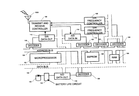
Fig. 3 shows a high level functional block diagram of a transmitter/receiver
module that is programmable for transmit and receive Garner frequencies. The
microprocessor 102 is any of a number of standard control microprocessors,
such as
an Intel 8501 microprocessor. The microprocessor 102 has a data bus 104 and an
address bus 106 (as well as standard power, ground, interrupts, etc.)
associated with it.
An antenna 100A is connected to a transmit/receive controller 100. The
transmit/receive controller 100 can have both a "receive" frequency and a
"transmit"
frequency. The frequency controllers 108, 110 shown in Fig. 3 control the
receive and
transmit frequencies, respectively. The Digital to Analog (D/A) Converter 112
2o converts the data on the data bus 104 to an analog voltage. The Analog to
Digital
(A/D) Converters 114, 116 change an analog signal to a set of digital signals
than can
be read as data on the data bus 104. The decoders 118, 120, 122, 124, 126 are
each set
for a particular address so that the microprocessor 102 can access a specific
device.
The Electrically Erasable Programmable Read Only Memory (EEPROM) 128 stores
the program that microprocessor 102 interprets and executes. The random access
memory (RAM) 130 is used to store information as needed by the program.
ATLANTA #2l 3786 v 1 1'j
CA 02315554 2000-08-09
Initially, the EEPROM 128 is loaded with a program to boot up and run and
manage the transmitter/receiver module. Once the system is turned on, the
microprocessor 102 sends out an address on the address bus 106, looking for a
control
program. The EEPROM 128 is programmed for this address and therefore, the
EEPROM 128 sends out data on the data bus 104 that the microprocessor 102 then
l0 interprets. Thus the relationship between the microprocessor 102 and the
EEPROM
128 has been established and the program now controls the system.
A subprocess of the system program is to initialize the transmit/receive
frequencies and to send out data using these frequencies to the nearest next
activated
transmitter/receiver module to become part of the wireless communication bus.
To
accomplish this, the program instructs the microprocessor 102 to set up the
transmit/receive frequencies. Addressing the decoders of the D/A frequency
controllers 108, 110 does this. Once a D/A frequency controller 108, 110 is
addressed
by its decoder 124, 122, the data on the data bus 104 is interpreted by this
D/A
frequency controller to supply an analog voltage (relative to the data on the
data bus)
2o to the transmit or receive input of the transmitlreceive controller 100.
This sets up the
Garner frequency of the transmitter or receiver controller. Both the
transmitter and
receiver Garner frequencies are established this way.
Next, the computer program instructs the microprocessor 102 to transmit a
protocol out to the wireless communication bus to notify the bus it is on-
line. The
program does this by first sending an address to the D/A data-out decoder 118.
Once
this D/A data-out decoder 118 is selected, the data on the data bus 104 is
sent to the
D/A data-out converter 112 and converted to an analog voltage and mixed with
the
ATLANTA #213786 v 1 1 g
CA 02315554 2000-08-09
transmit carrier frequency to send the signal out through the transmit/receive
controller 100. The digital data-out is sent as a continuous stream, sending
out a
continuous analog signal.
Once the program is finished sending out the needed protocol, the D/A data-
out decoder 118 is deselected and the A/D data-in decoder 120 is selected.
This is
to accomplished in the same way as before, i.e., the address bus 106 sends out
an address
that is the address of the AID data-in decoder 120, which selects the A/D data-
in the
system. This is used to interpret the received analog signal (less the carrier
frequency).
Digitizing that data by AID converter 114 sends out a data stream on the data
bus 104.
The microprocessor 102 interprets the data in looking for a particular
protocol (i.e.,
string of data) that is interpreted as being recognized. In this way, the
program and
the microprocessor 102 "handshake" transmit and receive signals, and therefore
the
EEPROM 128 program can literally provide any management system necessary.
Another part of the program is to look at battery life if the unit is powered
by
battery 134. The program instructs the microprocessor, at certain time
intervals, to
2o send out an address that is interpreted by the decoder 126 of the battery
circuit 132.
Once this battery circuit 132 is initialized, the A/D data-out converter 116
takes the
analog voltage off the battery life circuit 132 and converts it to a digital
data stream.
This information is interpreted by the program and also stored in the RAM 130.
Once
enough data is collected, new data over time is compared to the stored data
and preset
values in the EEPROM 128 to determine if the battery 134 needs to be replaced.
Once
this occurs, the program transmits this information over the wireless
communication
bus 20 to notify the user to change the battery 134.
ATLANTA #213786 v 1 19
CA 02315554 2000-08-09
What has been described herein is a ceiling grid system that becomes a
wireless communication plane providing an umbrella of connectivity for
devices. The
devices can span a range from appliances to computer clients (workstations,
laptops,
hand-held devices, etc.). As described herein, the wireless networking
components
can be embedded in the ceiling panel. The components include miniature
antennas,
single chip transceivers, sensors, power supplies, microprocessors, etc.
A software system can be used to fully enable the benefits of this wireless
infrastructure. A suite of software applications can range from automatic
remote
climate control/sensing to speaker and light activation, asset management
through
active bar code reading, point-of sale service, voice and data transfer as
well as peer-
to-peer electronic mail. Seamless roaming computing service to a client device
is
thereby provided.
The corresponding structures, materials, acts and equivalents of all means
plus
function elements in the claims are intended to include any structure,
material, or acts
for performing the functions in combination with other claimed elements as
2o specifically claimed.
While the invention has been particularly shown and described with reference
to a preferred embodiment thereof, it will be understood by those skilled in
the art that
various other changes in form and detail may be made without departing from
the
spirit and scope of the invention.
ATLANTA #213786 v 1 20