Note: Descriptions are shown in the official language in which they were submitted.
CA 02315630 2000-06-22
PCT/EP98/07578 (WO 99/35898)Lehmann, Erich
Device, especially for growing plants
The invention relates to a device, especially for growing plants, according to
the preamble of
claim 1.
to Devices are known from practice which are also called growing pot or
growing plate.
Regarding these pots the base of the respective pot is normally provided with
a plurality of
openings through which excess pouring water may be discharged from the pot.
Such pots
normally have a circular cross section conically enlarging from the base to
the upper pot
opening. Such pots are used in many gardening establishments and plant
nurseries for the
propagation, growing and further culture of plants, and may however also serve
for
arranging plants of either kind in the household.
With respect to such pots the following problem arises regarding the growing
of the roots. If
the root strikes against the pot wall, the root cannot penetrate the wall and,
therefore, grows
2o along the pot wall spirally downward to the base of the pot. As soon as the
root has reached
the base of the pot, the root grows annularly along the pot wall such that an
uncontrolled
turning growth of the roots takes place in the pot. The roots are not in a
position to grow
back into the centre of the pot. Such a strong turning growth of the roots may
disadvantageously affect the growth of the plant especially during a later
setting-out.
The essential disadvantages are to be seen in that
- the predominant turning growth of the roots in the pot will also be
maintained after the
setting-out of the plant into open land and that the roots can only poorly
break out of the
turning growth. Therefore, rooting of the earth shall take place only with
delay. This
3o leads to a reduced absorption of water and nutrients by the roots;
CA 02315630 2000-06-22
2
with increasing thickness of the root the turning growth in course of time
leads
to a constriction of the root neck, the absorption of water and nutriens is
further negatively affected thereby;
because of the reduced rooting in the earth only an insufficient anchoring of
the
plant in the soil takes place such that the danger that for instance deciduous
trees or conifers may all down is substantially increased;
the reduced rooting out of the turning growth also implies an increased
cultivation effort during the first time after the setting-out since an
exsiccating
of the conglomerate of roots may occur due to the poor rooting of the roots in
the surrounding earth. Such plants are hence to be watered more often and
possibly with greater water volumes.
Furthermore, so-called growing plates are known from practice which comprise a
plurality of combined pots. The turning growth of the roots may in fact be
prevented
with respect to growing plates without base; this however leads to an
increased
expenditure of labour since the growing plates are to be arranged in a raised
position,
and only growing plates having small pots may be used, since the substrate,
like for
example peat, sand or a clay mixture, or the humus soil would fall through the
pot
being formed without base with respect to growing plates comprising pots
having
greater diameters.
A device according to the above mentioned manner is known from US-A-4 510 712.
In this document the problem of the spiral growth of the roots is mentioned.
According
to an embodiment mentioned in this document vertical, narrow air gaps are
provided
close to the pot wall, the air gaps substantially extending over the entire
pot height.
There is the danger with respect to this embodiment that the air gaps will be
blocked
by roots after a relatively short time such that the known device can no
longer be
operated in a satisfactory manner.
Examples for pots having openings in the base are further known from the
journal
"Gartnerborse 17/1995, page 746". The growing pot known from EP-Al-0 599 798
A~"~~~~~ s um~
CA 02315630 2000-06-22
2a
comprises a lateral drain opening debouching into a cavity which is at least
partly
confined to the outside by ridges. According to this document each cavity is
confined
by side walls.
A~,.~.~,.~~~ Sa~L~
CA 02315630 2000-06-22
3
It is an object of the present invention to provide a device especially for
growing plants
according to which the turning growth of the roots is effectively prevented in
a simple
manner.
According to the present invention this object is solved by a device of the
predescribed
manner comprising the features of claim 1.
According to the present invention the first part of the opening is covered in
the inner space
of the pot by forming lateral openings by means of a ridge which is at least
partly set at a
l0 distance from the base. During the filling of the pot for example with
humus the ridge
prevents a penetration of the humus into the at least one opening such that
the opening will
not be filled with earth or substrate. Thus, a radially arranged passage
opening is formed
respectively between the ridge and the base of the pot on each side of the
ridge. As soon as
the roots reach the open air through the passage opening they come into
contact with light
and the surrounding atmosphere, like for example air. As a result, the root
tips die, and the
undesired turning growth of the roots does not take place any longer. It is
further
advantageous that the plant will faster continue with growing after being
repotted or trans-
planted into a larger pot or into open land, since the roots the tips of which
have been died in
the region of the passage openings, start at once with the new formation of
roots after
2o contact with the earth. This leads to a faster rooting out of the old
conglomerate of roots
and to a "better bearing" connecting between the plant and the new earth or
substrate. By
means of the strong new formation of the roots a good anchoring of the plant
in the soil
takes place in every direction such that the danger of falling down for the
plant occurs less
often. As a result, the prevention of turning growth of the roots of plants is
effectively
possible in a simple manner.
It is further advantageous that the ridge is arranged in a substantially
horizontal direction or
that the ridge is formed in a V-shaped manner having the tip directed to the
first part of the
at least one opening, wherein the tip of the ridge preferably lies in the
plane of the underside
of the base. The V-shaped forming of the ridge may prevent a further growing
of the root
CA 02315630 2000-06-22
4
over the first part of the opening and, therefore, the turning growth of the
root especially
regarding pots having small diameters.
According to a further embodiment of the present invention, the first part of
the at least one
opening is formed in the base like a rectangle and has a longitudinal axis
extending in a radial
direction of the pot. It is ensured thereby that a root growing at the base of
the pot in the
circumferential direction thereof reaches the region of the opening at the
latest after one
complete turning and, therefore, comes into contact with light and air such
that a further
turning growth of the root is prevented. By means of the particular formation
of the at least
to one opening comprising two parts formed in the base and in the pot wall,
the device
according to the present invention may be put down on a ground without problem
since the
portion (cavity) arranged between the passage openings and covered by the
ridge is
sufficiently provided with light and oxygen also in this case.
It is further advantageous that the second part of the at least one opening
formed in the
region of the pot wall close to the base trapezoidally enlarges to the base or
is shaped in the
form of two adjacent triangular openings having tips directed to the filling
opening of the
pot. This embodiment of the present invention contributes to a good
stackability of the
subject matter of the present invention. Moreover, the second part of the at
least one
opening receives more light and oxygen in its portion close to the base by
means of the
trapezoidal or doubly provided triangular form of said second part than in a
region farther
away from the base.
According to another embodiment of the present invention, one end of the ridge
is connected
to the pot wall and the opposing, other end of the ridge is connected with the
base by means
of a nearly vertical wall. It is ensured thereby that the ridge is not pressed
downward by a
higher weight of the humus or the plant and that the cross-section of each
passage opening is
also completely maintained with respect to an increased weight acting onto the
ridge from
above. A constriction or reduction of the cross-sectional area of the passage
openings are
CA 02315630 2000-06-22
effectively prevented by such a supporting of the ridge. Large passage
openings block less
easy and render possible a safer discharging of excess pouring water.
It is further advantageous that the ridge is slightly narrower and shorter
than the underlying
5 first part of the at least one opening formed in the base and that the wall
is trapezoidally
enlarged toward the base as well as slightly inclined to the edge of the pot.
These features of
the subject matter of the present invention favour like the predescribed
trapezoidal form of
the second part of the at least one opening a good stackability of the subject
matter of the
present invention.
According to a further embodiment of the present invention, the at least one
ridge comprises
a radially arranged, vertical partition wall on its bottom side directed to
the first part of the at
least one opening formed in the bottom in the level of its equally radially
disposed center line
over its entire length, the bottom edge of the partition wall being nearly
aligned with the
bottom side of the base. Thus, a circumferential further growing of the roots
is effectively
prevented above all with respect to smaller pots having a narrow first part of
the at least one
opening formed in the base, and a bridging of this part of the opening by the
roots is also
effectively prevented.
2o According to another embodiment of the present invention, four openings are
provided,
respectively adjacent openings enclosing an angle of about 90° in the
circumferential
direction of the pot. The turning growth of the roots is further reduced
thereby, since a root
growing along the base in the circumferential direction of the pot early comes
into contact
with an opening and, therefore, with light and air and dies at its tip.
According to an advantageous embodiment of the present invention, the pot wall
comprises
at least one substantially vertical guide rib extending away from the inner
side of the pot wall
in a radial direction to the inner space of the pot. The guide rib preferably
has a nearly
triangular cross-section decreasing from the base to the filling opening of
the pot. By means
of this feature a turning growth of the roots of the plants is further
reduced, since the roots
CA 02315630 2000-06-22
6
are already prevented from further growing in the circumferential direction of
the pot above
the base. As a result, the roots are early directed to the bottom and come
soon into contact
with one of the openings according to the present invention. The cross-section
of the guide
ribs decreasing from bottom to top facilitates the stacking of the device,
since the guiding
ribs further comprise a centering effect in the sense of a double action.
It is further advantageous that four guide ribs are provided and that
respectively adjacent
guide ribs enclose an angle of about 90° in the circumferential
direction of the pot.
According to a preferred embodiment of the present invention, guide ribs and
openings
to alternate in the circumferential direction of the pot or coincide such that
a guide rib extends
away from a ridge along the pot wall. Thus, the roots directed to the base by
means of a
guide rib come into contact with the opening after a 1/8 or 1/4 turning,
respectively, such
that the turning growth is effectively prevented in an early state.
In the following, embodiments of the present invention are explained in more
detail with
respect to the drawing wherein
Fig. 1 is a perspective view of a first embodiment of a device for growing
plants wherein
the device is shown standing on the top, i.e. with the base upward, for the
purpose
of a better graphical representation of the features according to the present
invention;
Fig. 2 is a top view of the embodiment of the device according to Fig. 1;
Fig. 3 is a schematic, perspective view of a vertical section through the
device for growing
plants;
Fig. 4 is a schematic, enlarged view of a part of the device shown in Fig. 3;
3o Fig. 5 is a perspective view of another embodiment of the device having V-
shaped ridges;
CA 02315630 2000-06-22
7
Fig. 6 is a perspective view of a further embodiment of the device from the
bottom having
guide ribs above the ridges; and
Fig. 7 is a schematic top view of the device according to Fig. 6.
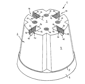
In Fig. 1 to 4 a first embodiment of a device 1 especially for growing plants
is schematically
shown in a perspective view. In the choosen embodiment the device 1 is a pot 2
which is
presented in Fig. 1 with its base 3 upward, i.e. standing on the top.
to
The pot 2 has a pot wall 4 connected with the base 3 which pot wall encloses a
circular
cross-section. According to Fig. 3 the pot wall 4 passes over a nearly
horizontal shoulder 5
to a drawn up edge 6. The area enclosed by the edge 6 forms the filling
opening 7 of the pot.
According to Fig. 1 and 2 the pot wall 4 is sonically formed and enlarged
toward the filling
opening 7 such that the respective pots can be stacked one upon the other
without problem
and the shoulder 5 of each upper pot lies upon the edge 6 of the underlying
pot in this
condition.
2o According to the present invention a plurality of openings 10, 11 is
provided in the base 3 of
the pot. The openings 11 are shaped in the form of circular holes. The other
openings 10
respectively comprise a first part 12 formed in the base 3 and extending to
pot wall 4 and a
second part 13 directly adjacent or combined therewith and formed in the
portion of the pot
wall 4 close to the base. As shown in Fig. 3 and 4 in more detail the first
part 12 of the
opening 10 formed in the base 3 is covered in the inner space 14 of the pot by
means of a
horizontal ridge 15 at least partly set at a distance from the base 3. The one
end of the ridge
15 is connected with the pot wall 4, and the opposing, other end of the ridge
15 is connected
with the base 3 by means of a vertical wall 16. In order to ensure or to
improve the
stackability of the pots 2 the ridge 15 is somewhat narrower and shorter than
the underlying
3o first part 12 of the opening 10 formed in the base 3. Moreover, the wall 16
for connecting
CA 02315630 2000-06-22
8
the inner end of the ridge with the base 3 is trapezoidally enlarged toward
the bottom 3 and
slightly inclined toward the pot wall 4.
The first part 12 of the opening 10 is rectangularly formed and has a
longitudinal axis 17
extending in the radial direction of the pot 2. In Fig. 1 the longitudinal
axis 17 is
schematically shown only with respect to one opening 10. It is further
apparent from Fig. 1
that the length of the first part 12 of the opening 10 is larger than the
width thereof.
The second part 13 of the opening 10 formed in the region of the pot wall 4
close to the base
to is trapezoidally formed and enlarged to the base 3 according to the first
embodiment as
shown in Fig. 1 to 4 such that the form of this second part 13 of the opening
10 nearly
corresponds with the form of the wall 16 supporting the ridge 15.
Due to the form of the openings 10 according to the present invention there is
on each side
of each ridge 15 a passage opening 20 shaded (section-lined) in Fig. 1 to 4,
respectively. It is
explicitely emphasized that for a better survey the passage openings 20 as
well as the
openings 11 in the base 3 are shaded and, in contrast to otherwise normal
graphical
respresentations, do not symbolize a section. According to the present
invention each
passage opening 20 extends directly up to the pot wall 4.
A further embodiment of the subject matter of the present invention is shown
in the left part
of Fig. 4. The ridge 15 shown therein comprises on its bottom side 21 in the
level of its
radial center line 22 over its entire length an equally radial, vertical
partition wall 23 the
bottom edge 24 of which is nearly aligned with the bottom side 25 of the base
3. The
partition wall 23 therefore subdivides the space between the ridge 15, wall
16, the passage
openings 20 and the first part 12 of the opening 10 concentrically in a radial
direction. Also
the second part 13 of the opening 10 which is arranged in the region of the
top wall 4 close
to the base, is concentrically subdivided by the partition wall 23.
CA 02315630 2000-06-22
9
According to Fig. 1 and 2 four rectangular openings 10 are altogether provided
in addition
to four circular openings 11 in the base. Adjacent openings 10 enclose an
angle 26 of about
90° in the circumferential direction of the pot 2 (see Fig. 4),
respectively. It is apparent that
the openings 10 may also enclose an angle other than 90°. This is
especially true with respect
to pots having a larger diameter and/or with respect to pots having more or
less than four
openings.
According to another embodiment of the present invention, the pot wall 4
comprises a
plurality of substantially vertical guide ribs 27 which extend from the inner
side 30 of the pot
1o wall 4 toward the inner space 14 of the pot in a radial direction starting
from the shoulder 5
up to the base 3. It is further to be seen from the Figures that each guide
rib 27 has a nearly
triangular cross-section and that the pot 2 has four guide ribs according to
the choosen
embodiment. Adjacent guide ribs 27 enclose an angle 31 of about 90° in
the circumferential
direction of the pot 2. Guide ribs 27 alternate with openings 10 in the
circumferential
direction of the pot 2. This is clearly to be seen in the schematical top view
shown in Fig. 2
of a pot 2 formed according to the present invention. It is apparent that the
guide ribs 27 are
arranged in parallel with the pot wall 4, and that, therefore, opposing guide
ribs 27 are
comically tapered toward the base 3 and that more or less than the shown four
guide ribs may
be provided such that also the angle 31 enclosed by adjacent guide ribs may
change. The
2o above mentioned angle 31 of 90° is therefore only stated as an
example. The arrangement
and form of the guide ribs further facilitates the stacking of a plurality of
pots 2 one upon the
other, since the guide ribs 27 engage each other, respectively, if a pot is
inserted into
another, lower pot from above. The openings 10 of the upper pot are aligned
with the ridges
15 of the lower pot.
The pot 2 may be made for instance of plastic material and may be manufactured
by an
injection molding or deep drawing process.
It is apparent that the device 1 according to the present invention may have
an arbitrary
3o cross-section, but that the device is preferably shaped in a circular or
angular form. It is
CA 02315630 2000-06-22
further possible to completely delete the openings 11 or, if circular openings
11 are formed
in the base, to vary form and number of these openings. Furthermore, the
invention is not
delimited to the shown form and number of the rectangular openings 10 and the
also
rectangular passage openings 20. It is likewise possible to provide for
example curved or
5 semicircular openings 10 and correspondingly curved passage openings 20.
A further embodiment of the device 1 according to the present invention is
shown in Fig. 5,
identical features indicating identical reference numerals if compared to the
first embodiment
according to Fig. 1 to 4
to
The ridge 15 of this embodiment is V-shaped having a tip 28 directed to the
first part 12 of
the opening 10. The second part 13 of the opening 10 thus has the form of two
adjacent
triangular openings 29 having tips 34 directed to the filling opening 7 of the
pot 2,
respectively. According to Fig. 5, the tip 28 of each ridge 15 lies in the
same plane as the
bottom side 25 of the base 3 of pot 2.
Also in this embodiment the visible passage openings 20 are shaded. As already
stated with
respect to Fig. 1 to 4 the shading regarding the passage openings 20 does not
represent a
section but an open area through which the roots may come from the inner space
14 of the
2o pot to the outer side and, hence, in contact with light and air.
Adjacent ridges 15 are connected to each other through walls 32 at their ends
directed to the
center point of the pot such that a trough-shaped recess 33 is formed in the
center of the pot
2. It is apparent that the passage openings 20 as well as the sides of each
ridge 15 are
inclined to the vertical. The same is true regarding the form of the walls 32.
Due to these
features also pots 2 of this embodiment may be stacked without problem.
The device according to the embodiment shown in Fig. 5 is especially suitable
for small,
preferably nearly square pots having curved edges. The dimensions of such pots
are about
3o between 7 cm x 7 cm x 7 cm (length x width x height) and 13 cm x 13 cm x 13
cm (length x
CA 02315630 2000-06-22
11
width x height). Pots exceeding the last mentioned volume are preferably
formed according
to the embodiment shown in Fig. 1 to 4.
Still a further embodiment of the device 1 according to the present invention
is shown in Fig.
6 and 7. Also in these graphical representations the shaded areas show through-
openings.
According to the perspective view of Fig. 6 each guide rib 27 is disposed
above a ridge 15.
Thus, a guide rib 27 respectively extends away from a ridge 15 along the pot
wall 4 toward
the upper edge 6 of the pot. According to this embodiment the cross-section of
each guide
to rib 27 decreases from ridge 15 toward the filling opening or the edge 6 of
the pot such that
each guide rib tapers toward its upper end. It is further to be seen from Fig.
6 that each ridge
ends directly at the lower end of each guide rib 27. A nearly triangular
recess 35 is
thereby formed at the end of each ridge close to the pot wall, the area of
said recess nearly
corresponding with the cross-section of the lower end of each guide rib 27.
This embodiment
15 has the advantage that there is still more incident light in the openings
such that the root tips
earlier come into contact with air and light in the region of the passage
openings 20 and die
thereby.
In the following the handling of the device according to the present invention
for growing
2o plants is described in more detail regarding the embodiment shown in Fig. 1
to 4.
In the pot 2, the bottom 3 of which is downwardly arranged, first of all the
appropriate
substrate, like for example humus, is filled in through the upper filling
opening 7. Then the
plant-seed, the plant-layer, the scion or the young plant is set in the
substrate. The size of the
pot is dependent on the size of the respective plant. It is often necessary
during the growing
or the further cultivation of the plants that the plants are repotted
according to their size, i.e.
that the plants first of all are set in small pots and are later repotted into
larger pots every
one or two years.
CA 02315630 2000-06-22
12
The growing roots tend to grow downwardly like a star away from the overground
part of
the plant. If the roots (not shown) strike against the pot wall 4, they
further grow
downwardly along the pot wall in a spiral manner, until the roots strike
against one of the
guide ribs 27. The guide ribs divert the roots in radial direction or toward
the base in axial
direction such that after further root growing the root tips soon strike
against the base 3 and,
after further expansion in the circumferential direction, on one of the
passage openings 20.
Since there is no substrate but light and air in the passage openings, the
root tips die in the
region of the passage openings 20. As a result, the unwanted turning growth of
the roots is
effectively prevented in a simple manner.
to