Note: Descriptions are shown in the official language in which they were submitted.
CA 02315697 2000-06-20
WO 99/32580 PCT/US98/27007
-1-
ZEOLITE L CATALYST IN A FURNACE REACTOR
FIELD OF THE INVENTION
The present invention relates to catalytic reforming using a catalyst
comprising
a non-acidic, monofunctional, large pore zeolite and a Group VIII metal having
a low
deactivation or fouling rate and high aromatics yield. More particularly, the
present
invention pertains to use of such catalyst in a gas or oil fired furnace.
BACKGROUND OF THE INVENTION
Reforming embraces several reactions, such as dehydrogenation,
isomerization, dehydroisomerization, cyclization and dehydrocyclization. In
the
process of the present invention, aromatics are formed from the feed
hydrocarbons to
the reforming reaction zone, and dehydrocyclization is the most important
reaction.
U.S. Patent No. 4,104,320 to Bernard and Nury discloses that it is possible to
dehydrocyclize paraffms to produce aromatics with high selectivity using a
monofunctional non-acidic type-zeolite L catalyst. The zeolite L based
catalyst in
'320 has exchangeable cations of which at least 90% are sodium, lithium,
potassium,
rubidium or cesium, and contains at least one Group VIII noble metal (or tin
or
germanium). In particular, catalysts having platinum on potassium form L-
zeolite
exchanged with a rubidium or cesium salt were claimed by Bernard and Nury to
achieve exceptionally high selectivity for n-hexane conversion to benzene. As
disclosed in the Bernard and Nury patent, the zeolite L is typically
synthesized in the
potassium form. A portion, usually not more than 80%, of the potassium cations
can
be exchanged so that other cations replace the exchangeable potassium.
Later, a further important step forward was disclosed in U.S. Patent
Nos. 4,434,311; 4,435,283; 4,447,316; and 4,517,306 to Buss and Hughes. The
Buss
and Hughes patents describe catalysts comprising a large pore zeolite
exchanged with
an alkaline earth metal (barium, strontium or calcium, preferably barium)
containing
CA 02315697 2000-06-20
WO 99132580 PCT/US98I27007
-2-
one or more Group VIII metals (preferably platinum) and their use in reforming
petroleum naphthas. An essential element in the catalyst is the alkaline earth
metal.
Especially when the alkaline earth metal is barium, and the large-pore zeolite
is
L-zeolite, the catalysts were found to provide even higher selectivities than
the
corresponding alkali exchanged L-zeoiite catalysts disclosed in U.S. Patent
No. 4,104,320.
These high selectivity catalysts of Bernard and Nury, and of Buss and Hughes,
are all "non-acidic" and are referred to as "monofunctional catalysts". These
catalysts
are highly selective for forming aromatics via dehydrocyclization of
paraffins.
Having discovered a highly selective catalyst, commercialization seemed
promising. Unfortunately, that was not the case, because the high selectivity,
L-zeolite catalysts did not achieve long enough run length to make them
feasible for
use in catalytic reforming. U.S. Patent No. 4,456,527 discloses the surprising
finding
that if the sulfur content of the feed was reduced to ultra low levels, below
levels used
in the past for catalysts especially sensitive to sulfur, that then long run
lengths could
be achieved with the L-zeolite non-acidic catalyst. Specifically, it was found
that the
concentration of sulfur in the hydrocarbon feed to the L-zeoiite catalyst
should be at
ultra low levels, preferably less than I00 parts per billion (ppb), more
preferably less
than 50 ppb, to achieve improved stability/activity for the catalyst used.
It was also found that zeolite L reforming catalysts are surprisingly
sensitive to
the presence of water, particularly while under reaction conditions. Water has
been
found to greatly accelerate the rate of deactivation of these catalysts. U.S.
Patent No.
4,830,732, which is herein incorporated by reference discloses the surprising
sensitivity of zeolite L catalysts to water and ways to mitigate the problem.
U.S. Patent No. 5,382,353 and U.S. Patent No. 5,620,937 to Mulaskey
et al.,which are herein incorporated by reference, disclose a zeolite L based
reforming
catalyst wherein the catalyst is treated at high temperature and low water
content to
thereby improve the stability of the catalyst, that is, to lower the
deactivation rate of
the catalyst under reforming conditions.
During commercialization of zeolite L reforming catalysts, it was found that
the ultra low sulfur levels caused the unexpected problem of coking,
carburization and
CA 02315697 2000-06-20
WO 99/32580 PCT/US98/27007
-3-
metal dusting of the reactor system metallurgy. This problem has necessitated
the use
of special steels and/or steels having protective layers to prevent coking,
carburization
and metal dusting. When used, protective layers are provided on the steel
surfaces
that are to be contacted with hydrocarbons at process temperatures, e.g., at
temperatures between about 800-1150°F. For example, a tin protective
layer has been
used in the reactors and furnace tubes of a catalytic reformer operated at
ultra low
sulfur levels. This has effectively reduced the rate of coke formation
exterior to the
catalyst particles in the reactors. Without this protection, coke buildup
would have
resulted in massive coke-plugging and in reactor system shutdowns. These
problems
are described in detail in Heyse et al., US 5,674,376. Heyse et al, disclose
the use of
special steels and protective coatings, including tin coatings, to prevent
carburizadon
and metal dusting. In a preferred embodiment, Heyse et al., teach applying a
tin paint
to a steel portion of a reactor system and heating in hydrogen to produce a
carburization-resistant intermetallic layer containing iron and nickel
stannides. The
reforming system of Heyse et al., is a high temperature, low sulfur and low
water
system that uses a conventional reformer designs, i.e., furnaces for heating
the feed
and catalysts located in conventional reactors.
Recently, several patents and patent applications of RAULO (Research
Association for Utilization of Light Oil) and Idemitsu Kosan Co. have been
published
relating to use of halogen in zeolite L based monofunctional reforming
catalysts.
Such halogen containing monofunctional catalysts have been reported to have
improved stability (catalyst life) when used in catalytic reforming,
particularly in
reforming feedstocks boiling above C~ hydrocarbons in addition to C6 and C7
hydrocarbons. In this regard, see EP 201,856A; EP 498,I82A; U.S. Patent
No. 4,681,865; and U.S. Patent No. 5,091,351.
EP 403,976 to Yoneda et al., and assigned to R.AULO, discloses the use of
fluorine treated zeolite L based catalysts in small diameter tubes of about
one-inch
inside diameter (22.2 mm to 28 mm in the examples). Heating medium proposed
for
the small tubes were molten metal or molten salt so as to maintain precise
control of
the temperature of the tubes. Accordingly, EP 403,976 does not teach the use
of a
conventional type furnace or conventional type furnace tubes. Conventional
furnaces
CA 02315697 2000-06-20
WO 99132580 PCTIUS98/27007
for catalytic reforming have tubes of usually three or more inches in inside
diameter
(76 mm or more), whereas EP 403,976 teaches that using tubes having an inside
diameter greater than 50 mm is undesirable. Also, conventional furnaces are
heated
using gas or oil fired burners.
Typical catalytic reforming processes employ a series of conventional furnaces
to heat the naphtha feedstock before each reforming reactor stage, as the
reforming
reaction is endothermic. Thus, in a three-stage reforming process, the overall
reforming unit would comprise a first fiunace followed by a first-stage
reactor vessel
containing the reforming catalyst (over which catalyst the endothermic
reforming
reaction occurs); a second furnace followed by a second-stage reactor
containing
reforming catalyst over which the reforming reaction is further progressed;
and a third
furnace followed by a third-stage reactor with catalyst to further progress
the
reforming reaction conversion levels.
For example, U.S. Patent No. 4,155,835 to Antal illustrates a three-stage
reforming process, with three furnaces (30, 44, 52) and three reforming
reactors (40,
48, 56) shown in the drawing in Antal. Example reforming reactors used
according to
the prior art are shown, for instance, in U.S. Patent No. 5,211,837 to Russ et
al.,
particularly the radial flow reactor shown in Figure 2 of Russ et al.
In some catalytic reforming units, as many as five or six stages of furnaces
followed by reactors are used in series for the catalytic reforming unit. In
particular,
reforming of hydrocarbons over a Pt L zeolite catalyst is a highly endothermic
reaction
and can require as many as 5 or 6 stages or more of furnaces followed by
reactors.
The present invention allows such a multistage process to be greatly
simplified to two,
or more preferably one, furnace reactor.
SUMMARY OF THE INVENTION
According to a preferred embodiment of the present invention, a process
for catalytic reforming of feed hydrocarbons is provided. The process
comprises
passing hydrocarbons over a catalyst comprising a Group VIII metal and a large
pore
zeolite disposed within a furnace, wherein said furnace comprises a first
chamber and
a second adjoining chamber separated by a heat exchange surface, wherein said
CA 02315697 2000-06-20
WO 99132580 PCT/US98I27007
-5-
catalyst is located within said first chamber and one or more burners are
located
within said second chamber. Preferably, the catalyst is no more than 4 inches
from
the heat exchange surface and at least a portion of the catalyst is more than
one inch
from the heat exchange surface.
A preferred embodiment of the process comprises contacting the feed,
under catalytic reforming conditions, with catalyst disposed in the tubes of a
furnace,
wherein the catalyst is a monofunctional, non-acidic catalyst and comprises a
Group VIII metal and zeolite L, and wherein the furnace tubes are from 2 to 8
inches
in inside diameter, and wherein the furnace tubes are heated, at least in
part, by gas or
oil burners located outside the furnace tubes.
In a preferred embodiment of the present invention, the furnace can be
basically a conventional type furnace, except that catalyst is disposed in the
tubes of
the furnace and the reactor metallurgy is constructed to avoid carburization
and metal
dusting problems caused by the low sulfur environment. The furnace is heated
by
conventional means for naphtha reforming units, such as by gas burners or oil
burners.
Also, in the present invention, the size of the tubes is conventional, in the
range 2 to
8 inches, preferably 3 to 6 inches, more preferably 3 to 4 inches, in inside
diameter.
Monofunctional zeolite L based catalyst is contained inside the tubes of the
conventional furnace in accordance with a particularly preferred embodiment of
the
present invention.
In a particularly preferred embodiment, the furnace tubes are made of a
material having a resistance to carburization and metal dusting under low
sulfur
reforming conditions at least as great as that of type 347 stainless steel.
The furnace
tubes can be:
(a) made of type 347 stainless steel or a steel having a resistance to
carburization and metal dusting at least as great as type 347 stainless steel;
or
(b) treated by a method comprising plating, cladding, painting or coating
the furnace tube surfaces for contacting the feed to provide improved
resistance to
carburization and metal dusting; or
(c) constructed of, or lined with, a ceramic material.
CA 02315697 2000-06-20
WO 99132580 PCT/US98/27007
_h_
Among other factors, the present invention is based on my conception and
unexpected finding that, using the catalysts defined herein, particularly non-
acidic,
monofunctional large pore zeolite based reforming catalyst, the conventional
arrangement of furnaces and multi-stage reforming reactors can be coalesced
into one
or more stages of conventional furnaces, eliminating the reformer reactor
vessels
downstream of the furnace. In one embodiment of the present invention, the
defined
monofunctional reforming catalyst is disposed in the tubes of a conventional
furnace.
A preferred embodiment of the present invention is also based on my finding
that a
conventional multi-stage furnaces/reactors reforming arrangement (consisting
of, for
example, three to six, or as many as nine stages of furnaces and reactors) can
be
replaced by as few as one basically conventional furnace containing
monofunctional
zeolite L reforming catalyst in the tubes of the furnace. The present
invention is also
based on my discovery that zeolite catalysts of improved stability (i.e.
having a
deactivation rate of less than 0.04 degrees F per hour at reforming
conditions) can be
effectively and economically used in a furnace reactor for catalytic
reforming. The
improved stability of these catalysts further allows them to be used at
operating
conditions that enable long run lengths without frequent or continuous
catalyst
regeneration. My invention allows for simplified processing schemes and
significantly less capital equipment than conventional catalytic reforming
systems.
In an alternative embodiment of the present invention the furnace may be
constructed such that the burners are located within tubes located in the
furnace and
the catalyst located in the area surrounding the tubes. The catalyst
containing area may
be a single chamber or a multitude of chambers. In such an arrangement it has
been
found that no portion of the catalyst should be more than 4 inches from the
tube
surface for heat flux reasons. Catalyst that is more than 4 inches from the
heated
surface may not be effective at dehydrocyclization of the hydrocarbons due to
the
highly endothermic nature of the dehydrocyclization reactions and the heat
flux
dependence on the distance from the burner tube or heat exchange surface. More
preferably the catalyst should be no more than 3 inches from a burner tube
surface.
Still more preferably the catalyst should be no more than 2 inches from a
burner tube
surface. It has also been found that there is preferably one or more inches of
catalyst
CA 02315697 2000-06-20
WO 99132580 PCT/ITS98/27007
packed around the burner tubes and more preferably 1.5 or more inches of
catalyst
packed around the burner tube surface. This reduces the amount of heat
exchange
surface in the furnace reactor and helps to minimize the number of furnace
reactors
required for reforming.
In still another embodiment of the present invention the furnace reactor
comprises two or more chambers. One or more chambers contain burners. One or
more adjoining chambers contain the catalyst. The burner chambers) and the
adjoining catalyst chambers) are separated by a surface effective to provide
heat
exchange. This surface between the burner chambers) and the catalyst chambers
is
herein referred to as the heat exchange surface. The chambers may have a
variety of
shapes. It is important however that catalyst should preferably be no more
than 4
inches from a heat exchange surface for heat flux reasons. Catalyst that is
more than
the preferred distance from the heated surface may not be effective at
dehydrocyclization of the hydrocarbons due to the highly endothermic nature of
the
dehydrocyclization reactions and the heat flux dependence on the distance from
the
heat exchange surface. Thus catalyst that is more than 4 inches from the heat
exchange surface may be effectively wasted. When I state that the catalyst is
no more
than an effective distance from the heat exchange surface to avoid wasting the
catalyst
it is meant that at least 80 % of the catalyst be within that distance from
the heat
exchange surface, preferably at least 85 % of the catalyst, more preferably at
least 90
%, still more preferably at least 95 %, and most preferably essentially all of
the
catalyst is whithin the stated distance from the heat exchange surface. As
stated above
I have found that for the catalyst of the present invention, the catalyst
should
preferably be no more than 4 inches from the heat exchange surface. More
preferably
the catalyst should be no more than 3 inches from the heat exchange surface.
Still
more preferably the catalyst should be no more than 2 inches from the heat
exchange
surface. It has also been found that there is preferably more than one, and
more
preferably I .5 or more, inches of catalyst packed around the heat exchange
surface.
This reduces the amount of heat exchange surface in the furnace reactor and
helps to
minimize the number of furnace reactors required for reforming.
CA 02315697 2000-06-20
WO 99/32580 PGT/US98/27007
_g_
As stated in the Background, U.S. Patent No. 4,155,835 illustrates the use of
a
three-stage reforming unit comprising three conventional furnaces, and three
reforming reactor vessels containing catalyst, with one reactor being located
downstream of each of the three furnaces. In contrast, the present invention
coalesces
or collapses the furnaces and separate reactors into one or more furnace tubes
reactor
system, without the separate reactor vessels. According tv the present
invention,
preferably, the system is only one furnace tube reactor, that is, coalescence
to one
furnace.
I have found that the present invention is particularly advantageously carried
out at relatively low hydrogen to hydrocarbon feed mole ratios of 0.5 to 3.0,
preferably
0.5 to 2.0, more preferably 1.0 to 2.0, most preferably 1.0 to 1.5, on a molar
basis.
I have also found that in the process of the present invention high space
velocities can be used. Preferred space velocities are from 1.0 to 7.0 volumes
of feed
per hour per volume of catalyst, more preferably 1.5 to 6 hour', and still
more
preferably 3 to 5 hour'
The relatively low hydrogen to hydrocarbon feed mole ratio and the high space
velocities when using the present invention make it feasible to use less total
catalyst
and at a lower overall gas flow rate. These benefits in turn allow the use of
a furnace
reactor with a reasonable number of tubes.
Preferably, the Group VIII metals used in the catalyst disposed in the furnace
tubes comprises platinum, palladium, iridium, and other Group VIII metals.
Platinum
is most preferred as the Group VIII metal in the catalyst used in the present
invention.
Also, preferred catalysts for use in the present invention are non-acidic
zeolite L catalysts, wherein exchangeable ions from the zeolite L, such as
sodium
and/or potassium, have been exchanged with alkali or alkaline earth metals. A
particularly preferred catalyst is Pt Ba L zeolite, wherein the zeolite L has
been
exchanged using a barium containing solution. These catalysts are described in
more
detail in the Buss and Hughes references cited above in the Background
section,
which references are incorporated herein by reference, particularly as to
description of
Pt L zeolite catalyst.
CA 02315697 2000-06-20
WO 99/32580 PCT/US98/27007
-9-
According to another preferred embodiment of the present invention, the
zeolite L based catalyst is produced by treatment in a gaseous environment in
a
temperature range between 1025°F and 1275°F while maintaining
the water level in
the effluent gas below 1000 ppm. Preferably, the high temperature treatment is
carried out at a water level in the effluent gas below 200 ppm. Preferred high
temperature treated catalysts are described in the Mulaskey et al. patents
cited above
in the Background section, which references are incorporated by reference
herein,
particularly as to description of high temperature treated Pt L zeolite
catalysts.
According to another preferred embodiment of the present invention, the
zeolite L based catalyst contains at least one halogen in an amount between
0.1 and
2.0 wt. % based on zeolite L. Preferably, the halogens are fluorine and
chlorine and
are present on the catalyst in an amount between 0.1 and 1.0 wt. % fluorine
and 0.1
and 1.0 wt. % chlorine at the Start of Run. Preferred halogen containing
catalysts are
described in the RAULO and IKC patents cited above in the Background section,
which references are incorporated by reference herein, particularly as to
description of
halogen containing Pt L zeolite catalysts. The above mentioned halogens may be
added to the catalyst ex situ for example when the catalyst is made or may be
added in
situ, for instance at the start of the run. The preferred halogen contents of
the catalyst
mentioned above should preferably be present on the catalyst at the start of
the run ,
when feed is introduced to the catalyst under reforming conditions.
Preferred feeds for the process of the present invention are naphtha boiling
range hydrocarbons, that is, hydrocarbons boiling within the range of C6 to
Clo
paraffms and naphthenes, more preferably in the range of C6 to C8 paraffins
and
naphthenes, and most preferably of C6 to C7 parafFms and naphthenes. The
feedstock
can contain minor amounts of hydrocarbons boiling outside the specified range,
such
as 5 to 20%, preferably only 2 to 7% by weight. There are several different
paraffins
at each of the various carbon numbers. Accordingly, it will be understood that
the
boiling point has some range or variation at a given carbon number cut point.
Typically, the paraffin rich feed is derived by fractionation of a petroleum
crude oil.
In a preferred embodiment of the present invention, the feed contacting the
catalyst preferably contains less than SO ppb sulfur, more preferably less
than 10 ppb
CA 02315697 2000-06-20
WO 99/32580 PCT/US98/27007
-10-
sulfur. In the present invention, low catalyst rates are important. Ultra low
sulfur in
the feed contributes to the success of the present invention. Two patents that
teach
about the need to avoid sulfur poisoning of Pt L zeolite catalysts and teach
how to
achieve ultra low sulfur conditions are U. S. Patents 4,456,527 and 5,322,615,
which
are herein incorporated by reference.
In one embodiment of the present invention, the furnace tubes are filled with
catalyst, and a conventional furnace with its associated tubes are used as a
combination heating means and catalytic reaction means.
In a particularly preferred embodiment of the present invention the catalyst
is
selected to have a particularly low deactivation rate under reforming
conditions:
Preferably, the catalyst selected for use and reaction conditions selected are
such that
the catalyst deactivation rate is controlled to less than 0.04°F per
hour, more
preferably less than 0.03°F, still more preferably less than
0.02°F, and most preferably
less than 0.01 °F per hour, at an aromatics yield of 50 wt % using a C6-
C7 UDEX
raffinate feed at a liquid hourly space velocity of 4 hour I and a hydrogen to
hydrocarbon mole ratio of 2. Utilizing a catalyst and conditions having the
particularly preferred low deactivation rate allows for less catalyst to be
used in the
furnace reactor and allows the use of larger diameter tubes. In another
embodiment of
the invention that does not use tubes, the catalyst can be further away from a
heat
exchange surface than when using a catalyst that has a high deactivation rate.
This in
turn allows the total length of tubes or in the alternative embodiment the
heat
exchange surface area to be minimized and makes it economical to replace the
multitude of furnace/ reactor loops (usually 3-6 or more reactors in a
conventional Pt
L zeolite catalyst reformer) with a single furnace reactor.
The present invention may again be contrasted to U.S. Patent No. 4,155,835 to
Antal. The Antal reference uses reformer reactor vessels separate from the
conventional furnaces, whereas the present invention does not.
Further, although the Antal process reduces the sulfur to very low sulfur
levels
in the feed, as low as 0.2 ppm sulfur, the present invention is preferably
carried out at
sulfur levels more than an order of magnitude lower, such as below 10 ppb
sulfur, in
CA 02315697 2000-06-20
WO 99/32580 PCT/US98/Z7007
-11-
the feed to the monofunctional zeolite L based catalyst contained in the
furnace
reactor system of the present invention.
Preferred reforming conditions for the furnace reactor of the present
invention
using the preferred catalyst comprising a monofunctional zeolite L include a
LHSV
between 1.5 and 6; a hydrogen to hydrocarbon ratio between 0.5 and 3.0; and a
heat
exchange surface temperature for the reactants (interior temperature) between
600°F
and 960°F at the inlet and between 860°F and 960°F at the
outlet at Start of Run
(SOR), and between 600°F and 1025°F at the inlet and between
920°F and 1025°F at
the outlet at End of Run (EOR). FOR is the time at which the run is ended
usually
due to deactivation of the catalyst. The catalyst of the present invention is
considered
at FOR at a point when the outlet temperature is no higher than 1025°F.
BRIEF DESCRIPTION OF THE DRAWINGS
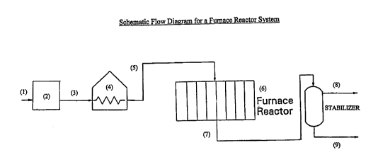
Figure 1 is a schematic flow diagram for a furnace tube reactor system.
Figure 2 is an overhead cross section view of a furnace tube reactor system
showing the burners (X) and the reactor tubes (o).
Figure 3 is a simplified scheme showing a vertical cross-section with gas-
fired
heaters (shaded) adjacent to a parallel series of furnace tubes that contain
catalyst.
Figure 4 shows 4 cross section views of alternative embodiment furnace
reactor systems showing the burners (X) and the catalyst chamber or chambers
as
cross-hatched areas.
DETAILED DESCRIPTION OF THE DRAWINGS
The drawing shown herein are for descriptive purposes only of possible
embodiments of the invention and are not intended in any way to limit the
invention.
Figure 1 is a schematic flow diagram for a furnace tube reactor system.
Hydrocarbon is fed to the unit through line (1). The sulfur content of the
hydrocarbon
is reduced to the desired low levels in the sulfur control unit (2). The
hydrocarbon
then goes via line (3) to an optional heat exchanger or preheater (4). The
optionally
heated effluent goes via line (5) to the furnace reactor (6) where it is
simultaneously
heated and contacted with the catalyst. The reactor effluent then goes via
line (7) to a
CA 02315697 2000-06-20
WO 99132580 PCT/US98/27007
-12-
stabilizer light gas is removed from the stabilizer by line (8) and liquid
product leaves
the stabilizer by line (9), which goes to product distillation (not shown).
Figure 2 is an overhead cross section view of a furnace tube reactor system
showing the burners (X) and the reactor tubes (o). The furnace tubes are
filled with
the catalyst. This is only one possible furnace tube arrangement.
Figure 3 is a simplified scheme showing a vertical cross-section with gas-
fired
heaters {shaded) adjacent to a parallel series of furnace tubes that contain
catalyst.
Figure 4 shows 4 cross section views of alternative embodiment furnace
reactor systems showing the burners (X) and the catalyst chamber or chambers
as
cross-hatched areas. There are numerous other possible furnace reactor
configurations. The four arrangements in Figure 4 are only meant as
illustrations of
possible embodiments of the chamber configurations useful in the present
invention
furnace reactor.
DETAILED DESCRIPTION OF THE INVENTION
The catalyst used in the process of the present invention comprises a
Group VIII metal and zeolite L. The catalyst of the present invention is a non-
acidic,
monofunctional catalyst.
The Group VIII metal of the catalyst of the present invention preferably is a
noble metal, such as platinum or palladium. Platinum is particularly
preferred.
Preferred amounts of platinum are 0.1 to S wt. %, more preferably 0.1 to 3 wt.
%, and
most preferably 0.3 to 1.5 wt. %, based on zeolite L.
In the present application the terms "L zeolite" and "zeolite L" are used
synonymously to refer to LTL type zeolite. The zeolite L component of the
catalyst is
described in published literature, such as U.S. Patent No. 3,216,789. The
chemical
formula for zeolite L may be represented as follows:
(0.9-1.3) M2i"O : A1203 (5.2-6.9) Si02 : yH20
wherein M designates a cation, n represents the valence of M, and y may be any
value
from 0 to about 9. Zeolite L, its X-ray diffraction pattern, its properties,
and method
for its preparation are described in detail in U.S. Patent No. 3,216,789.
Zeolite L has
been characterized in "Zeolite Molecular Sieves" by Donald W. Breck, John
Wiley
CA 02315697 2000-06-20
WO 99132580 PCT/US98/27007
-13-
and Sons, 1974, (reprinted I 984) as having a framework comprising 18
tetrahedra unit
cancrinite-type cages linked by double six rings in columns and cross-linked
by single
oxygen bridges to form planar 12-membered rings. The hydrocarbon sorption
pores
for zeolite L are reportedly approximately 7~ in diameter. The Breck reference
and
U.S. Patent No. 3,216,789 are incorporated herein by reference, particularly
with
respect to their disclosure of zeolite L.
The various zeolites are generally defined in terms of their X-ray diffraction
patterns. Several factors have an effect on the X-ray diffraction pattern of a
zeolite.
Such factors include temperature, pressure, crystal size, impurities and type
of cations
present. For instance, as the crystal size of the type-L zeolite becomes
smaller, the
X-ray diffraction pattern becomes somewhat broader and less precise. Thus, the
term
"zeolite L" includes any of the various zeolites made of cancrinite cages
having an
X-ray diffraction pattern substantially the same as the X-ray diffraction
patterns
shown in U.S. Patent No. 3,216,789. Type-L zeolites are conventionally
synthesized
in the potassium form, that is, in the theoretical formula previously given;
most of the
M cations are potassium. M cations are exchangeable so that a given type-L
zeolite,
for example, a type-L zeolite in the potassium form, can be used to obtain
type-L
zeolites containing other cations by subjecting the type-L zeolite to ion-
exchange
treatment in an aqueous solution of an appropriate salt or salts. However, it
is
difficult to exchange all the original cations, for example, potassium, since
some
cations in the zeolite are in sites that are difficult for the reagents to
reach. Preferred
L zeolites for use in the present invention are those synthesized in the
potassium form.
Preferably, the potassium form L zeolite is ion exchanged to replace a portion
of the
potassium, most preferably with an alkaline earth metal, barium being an
especially
preferred alkaline earth metal for this purpose as previously stated.
The catalysts used in the process of the present invention are monofunctional
catalysts, meaning that they do not have the acidic function of conventional
reforming
catalysts. Traditional or conventional reforming catalysts are bifunctional,
in that they
have an acidic function and a metallic function. Examples of bifunctional
catalysts
include platinum on acidic alumina as disclosed in U.S. Patent No. 3,006,841
to
Haensel; platinum-rhenium on acidic alumina as disclosed in U.S. Patent
CA 02315697 2000-06-20
WO 99132580 PCT/US98I27007
-14-
No. 3,415,737 to Kluksdahl; platinum-tin on acidic alumina; and platinum-
iridium
with bismuth on an acidic carrier as disclosed in U.S. Patent No. 3,878,089 to
Wilhelm (see also the other acidic catalysts containing bismuth, cited above
in the
Background section).
Examples of monofunctional catalysts include platinum on zeolite L, wherein
the zeolite L has been exchanged with an alkali metal, as disclosed in U.S.
Patent
No. 4,104,320 to Bernard et al.; platinum on zeolite L, wherein the zeolite L
has been
exchanged with an alkaline earth metal, as disclosed in U.S. Patent No.
4,634,518 to
Buss and Hughes; platinum on zeolite L as disclosed in U.S. Patent No.
4,456,527 to
Buss, Field and Robinson; and platinum on halogenated zeolite L as disclosed
in the
RAULO and IKC patents cited above.
According to another embodiment of the present invention, the catalyst is a
high temperature reduced or activated (HTR) catalyst.
Preferably, the pretreatment process used on the catalyst occurs in the
presence
of a reducing gas such as hydrogen, as described in U.S. Patent No. 5,382,353
issued
January 17, 1995,and U.S. Patent application 08/475,821, which are hereby
expressly
incorporated by reference in their entirety. Generally, the contacting occurs
at a
pressure of from 0 to 300 psig and a temperature of from 1025°F to
1275°F for from
1 hour to 120 hours, more preferably for at least 2 hours, and most preferably
for at
least 4-48 hours. More preferably, the temperature is from 1050°F to
1250°F. In
general, the length of time for the pretreatment will be somewhat dependent
upon the
final treatment temperature, with the higher the final temperature the shorter
the
treatment time that is needed.
For a commercial size plant, it is necessary to limit the moisture content of
the
environment during the high temperature treatment in order to prevent
significant
catalyst deactivation. In the temperature range of from 1025°F to
1275°F, the
presence of moisture is believed to have a severely detrimental effect on the
catalyst
activity. It has therefore been found necessary to limit the moisture content
of the
environment to as little water as possible during said treatment period, to at
least less
34 than 200 ppmv, preferably less than 100 ppmv water.
CA 02315697 2000-06-20
WO 99/32580 PCT/US98127007
-15-
In one embodiment, in order to limit exposure of the catalyst to water vapor
at
high temperatures, it is preferred that the catalyst be reduced initially at a
temperature
between 300°F and 700°F. After most of the water generated
during catalyst
reduction has evolved from the catalyst, the temperature is raised slowly in
ramping or
stepwise fashion to a maximum temperature between 1025°F and
1250°F.
The temperature program and gas flow rates should be selected to limit water
vapor levels in the reactor effluent to less than 200 ppmv and, preferably,
less than
100 ppmv when the catalyst bed temperature exceeds 1025°F. The rate of
temperature
increase to the final activation temperature will typically average between 5
and 50°F
per hour. Generally, the catalyst will be heated at a rate between 10 and
25°F per
hour. It is preferred that the gas flow through the catalyst bed during this
process
exceed 500 volumes per volume of catalyst per hour, where the gas flow volume
is
measured at standard conditions of one atmosphere and 60°F. In other
words, the gas
flow volume is greater than 500 gas hourly space volume (GHSV). GHSVs in
excess
of 5000 per hour will normally exceed the compressor capacity. GHSVs between
600
and 2000 per hour are most preferred.
The pretreatment process occurs prior to contacting the reforming catalyst
with
a hydrocarbon feed. The large-pore zeolitic catalyst is generally treated in a
reducing
atmosphere in the temperature range of from 1025°F to 1275°F.
Although other
reducing gasses can be used, dry hydrogen is preferred as a reducing gas. The
hydrogen is generally mixed with an inert gas such as nitrogen, with the
amount of
hydrogen in the mixture generally ranging from 1 % to 99% by volume. More
typically, however, the amount of hydrogen in the mixture ranges from about 10
to
50% by volume.
In another embodiment, the catalyst can be pretreated using an inert gaseous
environment in the temperature range of from 1025-1275°F, as described
in U.S.
patent application number 08/450,697, filed May 25, 1995, which is hereby
expressly
incorporated by reference in its entirety.
The preferred inert gas is nitrogen, for reasons of availability and cost.
Other
inert gases, however, can be used such as helium, argon, and krypton or
mixtures
thereof.
CA 02315697 2000-06-20
WO 99132580 PCTIUS98I27007
-16-
According to an especially preferred embodiment of the present invention, the
non-acidic, monofunctional catalyst used in the process of the present
invention
contains a halogen. This may be confusing at first, in that halogens are often
used to
contribute to the acidity of alumina supports for acidic, bifunctional
reforming
catalysts. However, the use of halogens with catalysts based on zeolite L can
be made
while retaining the non-acidic, monofunctional characteristic of the catalyst.
Methods
for making non-acidic halogen containing zeolite L based catalysts are
disclosed in the
R.AULO and IKC references cited above in the Background section.
The term "non-acidic" is understood by those skilled in this area of art,
particularly by the contrast between monofunctional (non-acidic) reforming
catalysts
and bifunctional (acidic) reforming catalysts. One method of achieving non-
acidity is
by the presence of alkali and/or alkaline earth metals in the zeolite L, and
preferably is
achieved, along with other enhancement of the catalyst, by exchanging cations
such as
sodium and/or potassium from the synthesized L zeolite using alkali or
alkaline earth
metals. Preferred alkali or alkaline earth metals for such exchanging include
potassium and barium.
The term "non-acidic" also connotes high selectivity of the catalyst for
conversion of aliphatics, especially paraffins, to aromatics, especially
benzene, toluene
and/or xylenes. High selectivity includes at least 30% selectivity for
aromatics
formation, preferably 40%, more preferably 50%. Selectivity is the percent of
the
conversion that goes to aromatics, especially to BTX (Benzene, Toluene,
Xylene)
aromatics when feeding a C6 to Cg aliphatic feed.
Preferred feeds to the process of the present invention are C6 to C9 naphthas.
The catalyst of the present invention has an advantage with paraffinic feeds,
which
normally give poor aromatics yields with conventional bifunctional reforming
catalysts. However, naphthenic feeds are also readily converted to aromatics
over the
catalyst of the present invention.
More preferably, feeds to the process of the present invention are C6 to C7
naphthas. The furnace reactor system of the present invention is particularly
advantageously applied to converting C6 and C7 naphthas to aromatics.
CA 02315697 2000-06-20
WO 99/32580 PCT/US98/27007
-17-
Particularly preferred catalytic reforming conditions for the present
invention
include, as described above under Summary of the Invention, an LHSV between
1.5
and 6.0-~, a hydrogen to hydrocarbon ratio between 0.5 and 2.0, a reactants
temperature between 600°F and 1025°F, and an outlet pressure
between 35 and
75 psig.
Preferably, the catalyst used in the process of the present invention is
bound.
Binding the catalyst improves its crush strength, compared to a non-bound
catalyst
comprising platinum on zeolite L powder. Preferred binders for the catalyst of
the
present invention are alumina or silica. Silica is especially preferred for
the catalyst
used in the present invention. Preferred amounts of binder are from 5 to 90
wt. % of
the finished catalyst, more preferably from 10 to 50 wt. %, and still more
preferably
from 10 to 30 wt. %.
As the catalyst may be bound or unbound, the weight percentages given herein
are based on the zeolite L component of the catalyst, unless otherwise
indicated
The term "catalyst" is used herein in a broad sense to include the final
catalyst
as well as precursors of the final catalyst. Precursors of the final catalyst
include, for
example, the unbound form of the catalyst and also the catalyst prior to final
activation by reduction. The term "catalyst" is thus used to refer to the
activated
catalyst in some contexts herein, and in other contexts to refer to precursor
forms of
the catalyst, as will be understood by skilled persons from the context.
Also with regard to use of the halogenated form of the monofunctional catalyst
in the present invention, the percent halogen in the catalyst is that at Start
of Run
(SOR). During the course of the run or use of the catalyst, some of the
halogen
usually is lost from the catalyst.
A preferred embodiment furnace tube reactor system of the present invention
refers to a reforming system in which non-acidic, highly selective zeolite L
based
catalyst is contained within a plurality of conventional furnace tubes which
are
themselves contained within a furnace. See Figure 1 which shows a schematic
diagram of a furnace reactor reforming process.
The furnace tubes are preferably parallel to each other and are preferably
vertically arranged. Typically, rows of furnace tubes alternate with rows of
burners.
CA 02315697 2000-06-20
_..
WO 99/32580 PCT/US98/27007
-18-
Figures 2 and 3 show a suitable arrangement for the burners and furnace tubes.
Figure
2 shows a horizontal cross section of the preferred embodiment furnace reactor
where
the Xs designate burners and the Os designate tubes. Figure 3 shows a
longitudinal
view of the preferred embodiment furnace tube reactor where the burners are
shown
impinging down parallel to the tubes.
The tubes are preferably 2 to 8 inches in diameter, more preferably 3 to
6 inches in diameter, and most preferably 3 to 4 inches in diameter, and can
be up to
45 feet long. The furnace tubes are preferably less than or equal to 30 feet
long and
preferably are at least 10 feet long. The arrangement of the furnace tubes and
the
burners can vary. Thus the furnace tubes can be positioned vertically, or
horizonontally, or in an arbor coil arrangement or in a helical coil
arrangement. The
burners can likewise be oriented in a number of different ways, for instance
at the
bottom of the furnace pointing up or at the side of the furnace pointing
horizontally.
Preferably the furnace tubes are positioned vertically with the burners
pointed down
parallel to the tubes.
Furnace reactors can be linked in series or in parallel, but preferably the
system is designed so that a single furnace reactor is used. Replacement of
the 3 to 6
or more conventional reforming reactors and furnace loops in a Pt L zeolite
reformer
with a single furnace reactor is preferable and is feasible with a Pt L
zeolite catalyst
having a high activity and a low deactivation rate. We have found that
replacement of
a multitude of conventional reactors and furnace loops results in greatly
reduced
investment costs for a Pt L zeolite reformer.
In a preferred embodiment, utilizing vertical tubes filled with catalyst, the
feed
comes in at the top of the tubes. The burners are mounted in the roof of the
fiunace
and fire down into the firebox. The maximum heat flux would then be at the
point
where feed is coming into the furnace tubes, which is desirable.
Alternatively, a
multi-zone furnace can be used. Here the heat flux can be varied more
controllably.
The heat flux supplied to the reactor inlets is preferably greater than that
applied near
the reactor outlet.
It is desirable that the furnace tube surfaces or the heat exchange surfaces
that
contact the hydrocarbons and resulting aromatics are made of a material having
a
CA 02315697 2000-06-20
WO 99/32580 PCT/US98I27007
-19-
resistance to carburization and metal dusting at least as great as that of
type 347
stainless steel under low sulfur reforming conditions. The resistance to
carburization
and metal dusting can be readily determined using the procedure outlined below
in
Example 4.
In a preferred embodiment of the invention, the furnace tube reactors are made
of (a) 347 stainless steel or a steel having a resistance to carburization and
metal
dusting at least as great as 347 stainless steel; or (b) the furnace tubes are
treated by a
method comprising plating, cladding, painting or coating the surfaces for
contacting
the feed to provide improved resistance to carburization and metal dusting; or
(c) the
furnace tubes are constructed of or lined with a ceramic material. More
preferably the
furnace tubes are constructed of a type 300 series steel provided with an
intermetallic
coating on the surfaces that contact hydrocarbons.
In one embodiment of the invention, the furnace tubes have a metal-containing
coating, cladding, plating, or paint applied to at least a portion (preferably
at least
50%, more preferably at least 75% and most preferably to all) of the surface
area that
is to be contacted with hydrocarbons at conversion temperature. After coating,
the
metal-coated reactor system is preferably heated to produce intermetallic
and/or metal
carbide layers. A preferred metal-coated reactor system preferably comprises a
base
construction material (such as a carbon steel, a chromium steel, or a
stainless steel)
having one or more adherent metallic layers attached thereto. Examples of
metallic
layers include elemental chromium and iron-tin intermetallic compounds such as
FeSn2.
As used herein, the term "metal-containing coating" or "coating" is intended
to
include claddings, platings, paints and other coatings that contain either
elemental
metals, metal oxides, organometallic compounds, metal alloys, mixtures of
these
components and the like. The metals) or metal compounds are preferably a key
components) of the coating. Flowable paints that can be sprayed or brushed are
a
preferred type of coating. In a preferred embodiment, the coated steel is heat
treated
to produce intermetallic compounds, thus reacting the coating metal with the
steel.
Especially preferred are metals that interact with, and preferably react with,
the
base material of the reactor system to produce a continuous and adherent
metallic
CA 02315697 2000-06-20
WO 99/32580 PCT/US98I27007
-20-
protective layer at temperatures below or at the intended hydrocarbon
conversion
conditions. Metals that melt below or at reforming process conditions are
especially
preferred as they can more readily provide complete coverage of the substrate
material. These metals include those selected from among tin, antimony,
germanium,
arsenic, bismuth, aluminum, gallium, indium, copper, lead, and mixtures,
intermetallic
compounds and alloys thereof. Preferred metal-containing coatings comprise
metals
selected from the group consisting of tin, antimony, germanium, arsenic,
bismuth,
aluminum, and mixtures, intermetallic compounds and alloys of these metals.
Especially preferred coatings include tin-, antimony-and germanium-containing
coatings. These metals will form continuous and adherent protective layers.
Tin
coatings are especially preferred -- they are easy to apply to steel, are
inexpensive and
are environmentally benign.
It is preferred that the coatings be sufficiently thick that they completely
cover
the base metallurgy and that the resulting protective layers remain intact
over years of
operation. For example, tin paints may be applied to a (wet) thickness of
between 1 to
6 mils, preferably between about 2 to 4 mils. In general, the thickness after
curing is
preferably between about 0.1 to 50 mils, more preferably between about 0.5 to
10
mils.
Metal-containing coatings can be applied in a variety of ways, which are well
known in the art, such as electroplating, chemical vapor deposition, and
sputtering, to
name just a few. Preferred methods of applying coatings include painting and
plating.
Where practical, it is preferred that the coating be applied in a paint-like
formulation
(hereinafter "paint"). Such a paint can be sprayed, brushed, pigged, etc. on
reactor
system surfaces.
One preferred protective layer is prepared from a metal-containing paint.
Preferably, the paint comprises or produces a reactive metal that interacts
with the
steel. Tin is a preferred metal and is exemplified herein; disclosures herein
about tin
are generally applicable to other metals such as germanium. Preferred paints
comprise
a metal component selected from the group consisting of a hydrogen
decomposable
metal compound such as an organometallic compound, finely divided metal and a
metal oxide, preferably a metal oxide that can be reduced at process or
furnace tube
CA 02315697 2000-06-20
WO 99/32580 PCT/US98/27007
-21-
temperatures In a preferred embodiment the cure step produces a metallic
protective
layer bonded to the steel through an intermediate bonding layer, for example a
carbide-rich bonding layer, as described in U.S. Patent No. 5,674,376, which
is
incorporated herein by reference in its entirety. This patent also describes
useful
coatings and paint formulations.
Tin protective layers are especially preferred. For example, a tin paint may
be
used. A preferred paint contains at least four components or their functional
equivalents: (i) a hydrogen decomposable tin compound, (ii) a solvent system,
(iii)
finely divided tin metal and (iv) tin oxide. As the hydrogen decomposable tin
compound, organometallic compounds such as tin octanoate or neodecanoate are
particularly useful. Component (iv), the tin oxide is a porous tin-containing
compound that can sponge-up the organometallic tin compound, and can be
reduced
to metallic tin. The paints preferably contain finely divided solids to
minimize
settling. Finely divided tin metal, component (iii) above, is also added to
insure that
metallic tin is available to react with the surface to be coated at as low a
temperature
as possible. The particle size of the tin is preferably small, for example one
to five
microns. Tin forms metallic stannides (e.g., iron stannides and nickel/iron
stannides)
when heated under reducing conditions, e.g. in the presence of hydrogen.
In one embodiment, there can be used a tin paint containing stannic oxide, tin
metal powder, isopropyl alcohol and 20% Tin Ten-Cem (manufactured by Mooney
Chemical Inc., Cleveland, Ohio). Twenty percent Tin Ten-Cem contains 20% tin
as
stannous octanoate in octanoic acid or stannous neodecanoate in neodecanoic
acid.
When tin paints are applied at appropriate thicknesses, heating under reducing
conditions will result in tin migrating to cover small regions (e.g., welds)
that were
not painted. This will completely coat the base metal.
Additional information on the composition of tin protective layers is
disclosed
in U.S. Patent No. 5,406,014 to Heyse et al., which is incorporated herein by
reference. Here it is taught that a double layer is formed when tin is coated
on a
chromium-rich, nickel-containing steel. Both an inner chromium-rich layer and
an
outer stannide layer are produced. The outer Layer contains nickel stannides.
When a
tin paint was applied to a 304 type stainless steel and heated at about 1200
°F, there
CA 02315697 2000-06-20
WO 99/32580 PCTIUS98I27007
-22-
resulted a chromium-rich steel layer containing about 17% chromium and
substantially no nickel, comparable to 430 grade stainless steel.
Tin/iron paints are also useful in the present invention. A preferred tin/iron
paint will contain various tin compounds to which iron has been added in
amounts up
to one third Fe/Sn by weight. The addition of iron can, for example, be in the
form of
Fe203. The addition of iron to a tin containing paint should afford noteworthy
advantages; in particular: (i) it should facilitate the reaction of the paint
to form iron
stannides thereby acting as a flux; (ii) it should dilute the nickel
concentration in the
stannide layer thereby providing a coating having better protection against
coking; and
{iii) it should result in a paint that affords the anti-coking protection of
iron stannides
even if the underlying surface does not react well.
Some of the coatings, such as the tin paint described above, are preferably
cured, for example, by heat treatment. Cure conditions depend on the
particular metal
coating and curing conditions that are selected so as to produce an adherent
protective
layer. Gas flow rates and contacting time depend on the cure temperature used,
the
coating metal and the specific components of the coating composition.
The coated materials are preferably cured in the absence of oxygen. If they
are
not already in the metallic state, they are preferably cured in a reducing
atmosphere,
preferably a hydrogen-containing atmosphere, at elevated temperatures. Cure
conditions depend on the coating metal and are selected so they produce a
continuous
and uninterrupted protective layer that adheres to the steel substrate. The
resulting
protective layer is able to withstand repeated temperature cycling, and does
not
degrade in the reaction environment. Preferred protective layers are also
useful in
reactor systems that are subjected to oxidizing environments, such as those
associated
with coke burn-off.
In general, the contacting of the reactor system having a metal-containing
coating, plating, cladding, paint or other coating applied to a portion
thereof with
hydrogen is done for a time and at a temperature sufficient to produce a
metallic
protective layer. These conditions may be readily determined. For example,
coated
coupons may be heated in the presence of hydrogen in a simple test apparatus;
the
formation of the protective layer may be determined using petrographic
analysis.
CA 02315697 2000-06-20
WO 99/32580 PCT/CIS98/27007
-23-
It is preferred that cure conditions result in a protective layer that is
firmly
bonded to the steel. This may be accomplished, for example, by curing the
applied
coating at elevated temperatures. Metal or metal compounds contained in the
paint,
plating, cladding or other coating are preferably cured under conditions
effective to
produce molten metals and/or compounds. Thus, germanium and antimony paints
are
preferably cured between 1000°F and 1400°F. Tin paints are
preferably cured
between 900°F and 1100°F. Curing is preferably done over a
period of hours, often
with temperatures increasing over time. The presence of hydrogen is especially
advantageous when the paint contains reducible oxides and/or oxygen-containing
organometallic compounds.
As an example of a suitable paint cure for a tin paint, the system including
painted portions can be pressurized with flowing nitrogen, followed by the
addition of
a hydrogen-containing stream. The reactor inlet temperature can be raised to
800°F at
a rate of SO-100°F/hr. Thereafter the temperature can be raised to a
level of 950-
975°F at a rate of 50°F/hr, and held within that range for about
48 hours.
The Furnace Tube Construction Material
There are a wide variety of base construction materials that can be used in
the
furnace tubes or the heat exchange surfaces. If the tubes/surfaces are to be
protected
with a metallic coating, then a wide range of steels may be used. In general,
steels are
chosen so that they meet the strength and flexibility requirements for the
catalytic
reforming process. These requirements are well known in the art and depend on
process conditions, such as operating temperatures and pressures.
Useful steels include carbon steel; low alloy steels such as 1.25, 2.5, 5, 7,
and
9 chrome steel; 300 series stainless steels including 304, 3I6 and 346; heat
resistant
steels including HK-40 and HP-50, as well as treated steels such as aluminized
or
chromized steels. Preferred steels include the 300 series stainless steels and
heat
resistant steels.
Depending on the components of the metal-containing coating, reaction of the
steel with the coating can occur. Preferably, the reaction results in an
intermediate
carbide-rich bonding or "glue" layer that is anchored to the steel and does
not readily
CA 02315697 2000-06-20
WO 99132580 PCTNS98/Z7007
-24-
peel or flake. For example, metallic tin, germanium and antimony (whether
applied
directly as a plating or cladding or produced in-situ) readily react with
steel at elevated
temperatures to form a bonding layer as is described in U.S. Patent No.
5,406,014 or
WO 94/15896, both to Heyse et al. The '014 patent is incorporated herein by
reference in its entirety.
If the tubes/surfaces are not to be protected with a metallic coating, they
can be
protected against carburization and metal dusting with a ceramic coating.
These types
of coatings are well known in the art. See US Pat. 4,161,510,
The furnace tube reactors may also be constructed of uncoated steels, so long
as the steels have a resistance to carburization and metal dusting at least as
great as
347 stainless steel under low sulfur reforming conditions. See Example 4
below.
Useful steels include the 300 series stainless steels including type 304, 316
and 34?
stainless steels; heat resistant steels including HK-40 and HP-50, as well as
treated
steels such as aluminized or chromized steels.
As stated earlier, I have also found that in the process of the present
invention
high space velocities are advantageously used. Relatively high space
velocities allow
lower total tube volume to be used. Lower space rates conversely require more
tube
volume to contain the appropriate (desired) amount of catalyst and thus may be
less
desirable, particularly if the total furnace size must be significantly larger
to
accommodate the increased volume of tubes.
The diameter and length of the furnace tubes can be varied so that a desired
pressure drop and heat flux across the tubes is attained. The length and
diameter of
the furnace tubes, and the location and number of burners, allow for
regulation of the
skin temperature of the furnace tubes as well as the radial and axial
temperature
profile of the furnace tubes. These parameters can be designed to allow for
appropriate conversion of particular feeds. However, the concept of the
present
invention requires that the furnace be basically conventional. Accordingly,
the size of
the furnace tubes will be at least two inches in inside diameter, more
preferably at
least three inches in inside diameter. Also, the furnace will be heated by
conventional
means, such as by gas or oil fired burners.
CA 02315697 2000-06-20
WO 99/32580 PCT/US98/27007
-25-
The pressure drop across the length of the furnace tubes preferably is less
than
or equal to 70 psi, more preferably less than 60 psi, most preferably less
than 50 psi.
The outlet pressure is preferably between 25 and 100 psig, more preferably
between
35 and 75 psig, and most preferably between 40 and 50 psig. The outlet
pressure is
the reaction mixture pressure at the outlet of the furnace tubes, that is, as
the tubes and
contained reaction mixture come out of the furnace.
To obtain a more complete understanding of the present invention, the
following examples illustrating certain aspects of the invention are set
forth. It should
be understood, however, that the invention is not intended to be limited in
any way to
the specific details of the examples.
EXAMPLES
Example 1
This example compares a conventional adiabatic multi-stage reactor system to
the externally heated furnace tube reactor of the present invention. The
catalyst used
in this comparison is platinum on halogenated zeolite L as disclosed in the
RALJLO
and IKC patents cited earlier. The total volume of catalyst in the two systems
is the
same. The same light naphtha is used as feed to both reactor systems. The
light
naphtha feed contained 2 percent CS's, 90 percent C6's (primarily paraffins
but also
minor amounts of naphthenes), and 8 percent by volume Cg's. The conditions and
parameters in the example have been adjusted to give the same total run length
for the
two systems in the comparison
CA 02315697 2000-06-20
WO 99132580 PCT/US98/27007
-26-
Externally Adiabatic
heated furnacemufti-stage
tube reactor reactor
system
1st 2nd 3rd 4th Sm 6th
Tube inner diameter, 3
inches
Number of tubes 800
Tube fen h, feet 15
Catal st volume, cubic580 60 60 60 1 115 170
feet I
5
Temperature at reactor900 945 950 955 960 965 970
inlet,
F
Inlet ressure, si 85 85
Outlet ressure 45 45
Liquid Hourly Space 4 4
Veloci , (1/hr.)
Feed Li t na htha Li
ht
na
htha
H2/H drocarbon mole 1 1
ratio
CS+ field, wt. % of 83.4 89.6
feed
Wt. % aromatics in 88.8 66:7
CS+
Aromatics Yield, wt% 74.1 59.8
of
feed
This example shows that, in accordance with the concept of the present
invention, a single externally heated conventional fiunace can effectively
replace a
six-reactor mufti-stage reactor system with catalyst disposed in the tubes of
the
furnace. The present invention also provides a substantially increased
aromatics yield.
The increase in yield results in more aromatics produced during the run.
Alternatively
the furnace tube reactor can be operated at lower severity allowing a much
lower
deactivation rate for a given yield thus allowing a run length of
substantially longer
than a year. We have also found the this result can be accomplished in the
furnace
tube reactor system of the present invention at a lower peak catalyst
temperature
versus the use of mufti-stage adiabatic reactors with conventional furnaces
preceding
each of the reactor stages.
CA 02315697 2000-06-20
WO 99/32580 PCTNS98/Z7007
-27-
Example 2
This example compares a conventional adiabatic multi-stage reactor system to
the furnace tube reactor system of the present invention. The catalyst used in
this
comparison is platinum on halogenated zeolite L, as disclosed in the RAULO and
IKC
patents cited earlier. The diameter of tubes in this example in the furnace
tube reactor
is larger than in the first example and the total volume of catalyst is twice
as much as
in the first example. The total volume of catalyst in the two compared systems
is the
same (1170 cubic feet). The same light naphtha is used as feed to both reactor
systems. The conditions and parameters in the example have been adjusted to
give the
same total run length for the two systems in the comparison. The feed rate of
the two
systems is also the same.
Furnace tube Adiabatic
reactor mufti-stage
reactor
system
1 2~a 3rd 4 S~ 6~
sr
Tube inner diameter, 4
inches
Number of tubes 610
Tube fen , feet 22
Catal st volume, cubic1170 120 120 120 230 230 350
feet
Temperature at reactor920 970 970 97~ 980 980 985
inlet, F
Inlet ressure, si 8$ gs
Outlet ressure 45 45
Liquid Hourly Space 2.0 2.0
Veloci , 1/hr.)
Feed Li t na htha Li
ht
na
htha
H2/H drocarbon mole 1.0 1.0
ratio
Cs+ field, wt. % of 78.9 86.4
feed
Wt. % aromatics in 93.9 80.0
CS+
Aromatics Yield, wt% 74.1 65.1
of
feed
This example shows that for a lower activity catalyst, at a lower space
velocity than
the previous example, in accordance with the concept of the present invention,
a
single furnace reactor with catalyst disposed in the tubes of the furnace can
effectively
CA 02315697 2000-06-20
WO 99/32580 PCTIUS98/27007
-28-
replace a six-reactor mufti-stage reactor system. This example also shows that
there is
a substantially better aromatics yield using the Furnace reactor. The increase
in yield
results in more aromatics produced during the run. Alternatively the furnace
tube
reactor can be operated at lower severity allowing a much lower deactivation
rate for a
given yield thus allowing a run length of substantially longer than a year.
Example 3
In the following example, a high temperature reduced catalyst is used in an
externally heated furnace tube reactor and compared to use of the same HTR
catalyst
in an adiabatic mufti-stage reactor system.
Externally Adiabatic
heated furnacemufti-stage
tube reactor reactor
system
1 2na 3ra 4m Sm 6u~
si
Tube inner diameter, 4
inches
Number of tubes 740
Tube fen h, feet 24
Catal st volume, cubic1550 150 150 150 320 320 460
feet
Temperature at reactor900 935 940 940 945 950 960
inlet, F
Inlet ressure, si 85 85
Outlet ressure 45 45
Liquid Hourly Space 1.5 1.5
Veloci , l/hr.
Feed Li t na htha Li
ht
na
htha
H2/H drocarbon mole 3 3
ratio
CS+ field, wt. % of 80.1 86.5
feed
Wt. % aromatics in 91.2 75.2
CS+
This example illustrates that a six-reactor mufti-stage reactor system can be
effectively replaced by a system in accord with the present invention wherein
catalyst
is disposed in the tubes of a conventional single externally heated furnace.
The
catalyst used in this example is a high temperature reduced catalyst
comprising Pt on
L zeolite. This example also illustrates that the system of the present
invention
provides an increased aromatics yield. This result is accomplished at a lower
peak
CA 02315697 2000-06-20
WO 99/32580 PCT/US98I27007
-29-
catalyst temperature in the externally heated furnace tube reactor system than
in the
system comprising several furnaces and separate reactors in series.
Example 4
To determine the resistance of various substrates to coking, carburization and
metal
dusting under ultra low sulfur reforming conditions, the following test can be
run.
The test makes it especially easy to do side by side comparisons, for example
comparisons with type 347 stainless steel.
The test uses a Lindberg quartz tube furnace with temperatures controlled to
within one degree with a thermocouple placed on the exterior of the tube in
the heated
zone. The furnace tube had an internal diameter of 5/8 inches. Several
preliminary
test runs are conducted at an applied temperature of 1200°F using a
thermocouple
suspended within the hot zone of the tube. The internal thermocouple
constantly
measured up to 10°F lower than the external thermocouple.
Samples of steels and other construction materials are then tested at
1100°F,
1150°F and 1200°F for 24 hr, and at 1100°F for 90 hr,
under conditions that simulate
the exposure of the materials under conditions of low-sulfur reforming. The
samples
of various materials should be clean and free of scale, grease or tarnish.
Compared
samples should be equally smooth. The samples are placed in an open quartz
boat
within the hot zone of the furnace tube. The boats are 1 by '/z inch and fit
well within
the two-inch hot zone of the tube. The boats are attached to silica glass rods
for easy
placement and removal. No internal thermocouple is used when the boats are
placed
inside the tube.
Prior to start-up, the test materials are cut to a size and shape suitable for
ready-visual identification. After any pretreatmEnt, such as roasting, the
samples are
weighed. Most samples weigh less than 300 mg. Typically, each run is conducted
with three to five samples in a boat. A sample of 347 stainless steel is
present in each
run as an internal standard.
After the samples are placed, the tube is flushed with sulfur-free nitrogen
for a
few minutes. A carburizing gas of a commercially bottled mixture of 7% propane
in
hydrogen is bubbled through a liter flask of high purity toluene at room
temperature in
CA 02315697 2000-06-20
WO 99/32580 PCT/US98/27007
-3 0-
order entrain about 1 % toluene in the feed gas mix. This carburizing gas
contains less
than 10 ppb sulfur. Gas flows of 25 to 30 cc/min., and atmospheric pressure,
are
maintained in the apparatus. The samples are brought to operating temperatures
at a
rate of about 100°F/min.
After exposing the materials to the carburizing gas for the desired time and
temperature, the apparatus is quenched with an air stream applied to the
exterior of the
tube. When the apparatus is sufficiently cool, the hydrocarbon gas is swept
out with
nitrogen and the boat is removed for inspection and analysis.
After completion of each run, the condition of the boat and each material is
carefully noted. Typically the boat is photographed. Then, each material and
its
associated coke and dust is weighed to determine changes. Care is taken to
keep any
coke deposits with the appropriate substrate material. The samples are then
mounted
in an epoxy resin, ground and polished in preparation for petrographic and
scanning
electron microscopy analysis. The degree of surface corrosion is determined;
this
indicates the metal dusting and carburization response of each material. In
general, a
qualitative visual analysis of metal reactivities is readily made.
The residence time of the carburizing gas used in these tests is considerably
higher than in typical commercial operation. Thus, it is believed that the
test
conditions may be more severe than commercial conditions. Nevertheless, the
test
provides a reliable indication of the relative resistance of the materials to
carburization
and metal dusting.
Example 5 -- Preparing Tin-Coated Steel
Pieces of 321 SS were coated with a tin-containing paint. The paint consisted
of a mixture of 2 parts powdered tin oxide, 2 parts finely powdered tin (1-5
microns),
1 part stannous neodecanoate in neodecanoic acid (20% Tin Tem-Cem manufactured
by Mooney Chemical Inc., Cleveland, Ohio which contained 20% tin as stannous
neodecanoate) mixed with isopropanol, as described in US 5.674.376. The
coating
was applied to the steel surface by painting and letting the paint dry in air.
After
drying, the painted steel was contacted with flowing hydrogen gas at
1100°F for 24
hours.
CA 02315697 2000-06-20
WO 99/32580 PCT/US98/27007
-31-
The resulting coated steel specimens with intermetallic tin layers were
examined visually for completeness of coating. Also, mounted and polished
cross-
sections of the materials when examined using petrographic and scanning
electron
microscopy. The micrographs showed that the tin paint had reduced to metallic
tin
under these conditions. A continuous and adherent metallic (iron/nickel
stannide)
protective layer was observed on the steel surface.
These techniques showed that tin intermetallic compounds, including nickel-
and iron-containing stannides, were present at a thickness of between about 2
to 5
microns. A nickel-depleted underlayer of a thickness of about 2-5 microns was
also
present. If the curing was done at lower temperature, this underlayer was not
formed.
Example 6 -- Analysis of Steel
Samples of coated and preferably heat cured steels were mounted in a clear
epoxy resin and then ground and polished in preparation for analysis with the
petrographic and scanning electron microscopes (SEM). Coupons were analyzed
before and after reforming conditions. EDX analysis can be used to determine
the
chemical composition of the layers. For example, tin intermetallic layers may
be
analyzed for iron, nickel and tin.
Example 7
Determination of the Deactivation Raze of a Catalyst
Deactivation rate of a catalyst sample as used in the present invention can be
determined in an isothermal pilot plant or similar unit under the following
standard
conditions using a standard feed.
The feed to the unit should be a C6-C7 UDEX raffinate from a conventional
reformer. The UDEX raffinate feed should have the following composition as
measured by Gas Chromatograph; a C6 paraffin content of 39 to 43 wt %, a total
C6
content of 45 to 50 wt %, a total C7 content of 25 to 35 wt %, a total CS
content of 5
to 11 wt%, and a total C8 content of less than 6 wt %. The feed should contain
less
than 10 ppb of sulfur and less than 3 ppm of water. The pilot plant should
also be free
CA 02315697 2000-06-20
WO 99/32580 PCT/US98/27007
-32-
of any other possible source of sulfur contamination. Care must be taken to
avoid
sulfur contamination of the system and to avoid using a previously sulfur
contaminated system. Two patents that teach how to clean-up a sulfur
contaminated
system are U. S. Patents 5,035,792 and 4,940,532 both of which are herein
incorporated by reference. The LHS V of the unit should be set at 4 ( 1 /hr)
with a
system pressure of 85 psig . The hydrogen/hydrocarbon mole ratio of the system
should be 2. The pilot plant unit should be operated at a temperature
sufficient to
maintain the aromatics in the reactor effluent at 50 wt %. The temperature is
increased to maintain the 50 wt % aromatics and the results plotted over a 8
week
period (1344 hours) of continuous stable operation under said conditions. The
fouling
rate can be determined for the period of stable operation by dividing the
change in
temperature over the period by the number of hours.