Note: Descriptions are shown in the official language in which they were submitted.
CA 02316057 2000-08-16
-1-
PROFILE EXTRUSION OF THERMOPLASTIC COMPOSITES
WITH HIGH FILLER CONTENT
FIELD OF THE INVENTION
The present invention relates to an extrusion
process and apparatus for the manufacture of extruded
profiles of thermoplastic composite materials with very high
filler content.
In a specific embodiment, this invention relates to
1o cellulosic filler reinforced thermoplastic composites that
have strength and modulus comparable to those of wood and
engineered wood products such as particleboard, medium
density fibreboard (MDF), plywood, etc. More specifically,
the process involves the use of a cooled shaper attached
directly to the end of the die via a thermal barrier. The
cooled shaper solidifies the outer skin of the profile
sufficiently to maintain the shape of the profile after it
exits the cooled shaper. The profile exiting the cooled
shaper is not drawn down and can be processed by
zo conventional post extrusion equipment (vacuum calibrator,
cut-off saw, etc).
BACKGROUND OF THE INVENTION
Profile extrusion processes have been developed over
2s many years. For example, various types of pipe have been
produced by extruding rigid PVC (polyvinylchloride), HDPE
(high-density polyethylene) and ABS (acrylonitrile
butadiene-styrene). Complex profiles, such as window frame,
siding, fencing and decking components have also been made
so with these processes, using, for example, rigid PVC. The
manufacture of these products is conducted using polymers
with no or relatively low filler content (less than 40% by
weight).
The conventional profile extrusion process requires
3s conditions where the temperature at the extrusion die is
well above the melting/softening point of the polymer. The
CA 02316057 2000-08-16
_Z_
profile exits the die in molten form, and is received in a
vacuum sizing tank/calibrator, which prevents the profile
from collapsing. The vacuum sizing tank/calibrator
comprises a solid structure with a bore therethrough
s matching the size and shape of the extruded profile. The
dimension and shape of the profile is maintained by applying
vacuum to the outer part of the profile while it is cooled.
In the conventional profile extrusion process, the
sizing vacuum tank/calibrator is not attached to the die.
~o Therefore, it is necessary that the profile exiting the die
does not swell nor melt fracture because the vacuum sizing
tank/calibrator cannot accommodate extrudate which has
undergone die swell and melt fracture. Die swell and melt
fracture are typical phenomena in profile extrusion when the
15 temperature of the polymer in the die is too low and/or the
viscosity of the molten polymer/composite at the die is too
high. This phenomenon is usually accompanied by high-
pressure drop across the die. To prevent these problems
profile extruders typically employ a pulley downstream of
zo the die. The pulley draws down the gauge of the profile,
counteracting the effects of die swell. The pulley also
lowers the die head pressure.
Known processes for the manufacture of composites
with high filler content mainly involve compression molding,
zs where a mixture of resin and filler is shaped in a mould by
pressing the two parts of the mould together. Most of these
processes use thermosetting resins, such as urea-
formaldehyde resins and melamine-formaldehyde, as the
binder/matrix, but some processes use thermoplastic resins.
3o With the thermosetting resins, the product can
contain up to 95o by weight of filler, because the binder is
in liquid form prior to a curing reaction. Mixing of such a
liquid with the filler can be done in a conventional mixer.
Particleboard (using wood particles) and MDF or medium
35 density fibreboard (using wood pulp) are typical examples of
such composites. The mixture is then compression molded
CA 02316057 2000-08-16
-3-
into sheet/board (particleboard and MDF) or into various
shapes, and heat is applied to cure the resin. Once the
curing process is complete, the product is cooled and
released from the mould. Products made from thermosetting
s resins are usually non-recyclable because thermosetting
resin cannot be re-melted and re-shaped once it is cured.
Recently, interest has developed in completely
recyclable products. Much effort has been put into
replacing thermosetting resins with thermoplastic resins,
~o especially those available in abundance in the post consumer
recycling stream, such as fractional melt (high viscosity)
HDPE from bottles and film (bags). With thermoplastic
resins, melt-mixing (compounding) of the resin and the
filler is required. Twin screw extruders and kneaders are
most commonly used for this purpose, but they are limited to
relatively low filler content or thermoplastic resins with
relatively low viscosity. This excludes mixing of
fractional melt HDPE with amounts of filler of 40% to 60% by
weight.
zo At least three other processes have been proposed
for melt-mixing or compounding thermoplastic resin with up
to 80o by weight of filler. They are all based on a high
speed, high shear thermokinetic mixing process. Once the
compound is prepared by mixing it is shaped into the final
z5 product. Using compression moulding, this compound can be
shaped into sheet/board and other shapes. Extrusion of such
a compound has also been explored.
U.S. Patent 5,516,472 to Zaver discloses a process
for combining an organic fibrous material with a
3o thermoplastic material forming a wood imitation composite.
The process comprises the steps of dry-blending the raw
materials, melt blending them in an extruder, passing the
homogenous mixture through a transition die to pre-shape the
mixture and to expand the mixture, passing the mixture
35 through a stranding die to form a plurality of strands, and
finally passing the plurality of strands through a moulding
CA 02316057 2000-08-16
-4-
die for a time sufficient to compress the strands together
and bond the strands to each other. The preferred
formulation of Laver's invention is approximately 65% wood
flour, 26o high density polyethylene over 3% processing aid
s and over 5% thermoset.
U.S. Patent 5,474,722 to Woodhams discloses a
process to produce a high modulus article consisting of a
composite of an oriented plastic material and an oriented
particulate material. The orientation results from forcing
~o the molten composite material through a converging passage
to produce an extrudate, deforming the extrudate while
maintaining the extrudate at or close to its melting
temperature (1-10°C above the melting temperature) to
produce an oriented deformed extrudate, and cooling the
~S deformed extrudate to preserve the orientation.
PCT Publication WO 94/11174 to Suwanda et al.
discloses a similar process to that of Woodhams, i.e. a
process for continuous production of filled thermoplastic
compound containing filler, having oriented components. The
zo process comprises the steps of bringing the material to a
molten stage, but at a temperature just above the softening
temperature (0-10°C above the melting temperature), forcing
the molten material through a converging die to impart
longitudinal orientation to the polymer and the filler
z5 particulates, and cooling the compound to preserve the
orientation.
The Laver process results in extrudate with poor
structural characteristics due to the large amount of
processing aid. Also the thermosetting components would
3o degrade upon recycling of the material. This would cause
the physical properties to degrade as well. Both processes
of Woodhams and Suwanda claim to be able to extrude
thermoplastic compound with up to 80o filler by weight into
profiles. Both also concentrate on designing the converging
35 flow through the die to control the elongational strain
CA 02316057 2000-08-16
-5-
necessary to create the orientation of polymer molecules as
well as the filler particulates.
SUMMARY OF THE INVENTION
s The present invention provides a process and an
apparatus for the continuous production of extruded profiles
of thermoplastic composites with very high filler content.
Such processes and apparatus may be used for the production
of both solid and hollow profiles. A thermoplastic compound
~o is provided comprising a mixture of thermoplastic polymer
and filler particles. The thermoplastic compound is fed
into an extruder where it is melted and pushed through a
specially designed die assembly.
The die assembly comprises one or more die parts, a
~s corresponding number of die lands to follow each die part,
and a cooled shaper, and, in the case of hollow profiles, a
mandrel. A die is defined as a part where a change in the
profile shape, i.e., deformation, takes place. The die land
is the straight part following the die, through which the
2o extrudate moves without a change in profile shape, allowing
the extrudate to relax from the stresses of extrusion
deformation.
The material deformation from the shape of the
extruder barrel (necessarily circular) to the final desired
25 profile may be conducted in one step, using one die or
multiple steps, using multiple dies arranged in series. The
dies) is (are) designed to ensure balanced flow can be
attained at high speed and low pressure drop. After each
deformation in a die, the material is stabilized and allowed
3o to relax from residual stresses resulting from deformation
in the die, using the die lands. The length of the die land
is typically 2-20 times the effective diameter (diameter of
a circular profile having the same area as the profile).
The temperature of the compound in each die and die
35 land is kept above the melting/softening point of the
polymer to allow deformation and relaxation to take place.
CA 02316057 2000-08-16
-6-
Optionally, lubricant may be introduced at this stage to
reduce pressure drop caused by shear stress at the wall of
each die and die land. Then the extrudate is fully or
partially solidified in a long cooled shaper, up to 200
s times the effective diameter of the extrudate. The cooling
system in the shaper removes heat from the extrudate. The
temperature of the cooled shaper is set low enough so that
the extrudate form a solid skin of sufficient thickness
before exiting the cooled shaper. The solid skin so formed
~o must be thick enough to prevent molten composite material in
the core of the extrudate from bulging or bursting through
the solid skin, or otherwise deforming the profile.
Significant pressure from the inner molten core is caused by
the elastic nature of the molten plastic and by the foaming
action of any residual moisture in the filler particles. As
the extrudate is cooled, it also shrinks, reducing the
friction between the composite and the wall of the cooled
shaper. External lubricant is used at this stage, to reduce
friction between the composite and the wall of the cooled
2o shaper, before sufficient shrinking is achieved, otherwise
the pressure drop across the cooled shaper will exceed the
limit a conventional extruder can withstand. Due to the
requirement of a sharp temperature drop between the die land
and the cooled shaper, a heat barrier between these two
zs pieces is used.
In the case of a hollow profile the die assembly
includes a mandrel. The mandrel mirrors the actions of the
aforementioned die, die land and cooling shaper. That is,
the section of the mandrel corresponding to the die is of
3o variable cross section in order to impart the required
deformation to the profile. This section of the mandrel is
neither heated nor cooled but is maintained at a temperature
above the softening point of the melt due to heat transfer
from the breaker plate, die and polymer melt. From the
35 point the melt enters the die land, the mandrel has the
approximate cross section of the final profile. Where the
CA 02316057 2000-08-16
melt enters the cooled shaper the corresponding section of
the mandrel is cooled. The mandrel is cooled by a cooling
system fed through spider legs in the die. The cooling
system is designed such that cooling is imparted in the
section of the mandrel corresponding to the cooled shaper
but not in the section corresponding to the die. Thus a
thermal gradient is set up in the mandrel. The temperature
in the die is above the softening point of the melt and in
the cooled shaper is below the softening point of the melt.
to The hollow profile is cooled from both the outside and the
inside in the area of the cooled shaper. As already
mentioned, the cooling must create a sufficiently solid skin
to prevent deformation of the profile. The cooling causes
the profile to shrink, constricting it around the mandrel.
The mandrel is slightly tapered towards the exit to reduce
the resulting friction. Optionally, lubricant can be
injected onto the inside surface. The lubricant may be fed
to the mandrel via the spider legs.
For both hollow and solid profiles, the extrudate
zo exiting the cooled shaper is conveyed to conventional
downstream equipment. From the cooled shaper, the extrudate
enters a vacuum sizer/calibrator. As in typical profile
extrusion processes, a pulley passes the extrudate to a cut
off saw and dump table. However, the pulley is not operated
z5 with the same purpose found in typical profile extrusion
processes. The pulley does not pull the extrudate with
enough force to deform the extrudate as it leaves the die
assembly. The extrudate is not drawn down nor does the
pulley impart orientation. The pulley operates at a linear
3o speed equivalent to the average velocity of the composite in
the cooled shaper. The pulley acts primarily to support the
extrudate and convey it to the cut off saws. The reason for
this is that the extrudate will not swell on exiting the die
assembly as in typical profile extrusion processes. The
35 profile already has the required dimensions. It does not
CA 02316057 2000-08-16
_ g _
need to be drawn down. In fact operating the pulley with a
high torque would fracture the extrudate.
According to a broad aspect of the present invention
there is provided an extrusion process for the manufacture
s of a thermoplastic resin-filler composite product. The
product has a desired resin-filler mixture comprised of 60-
20% by weight of a thermoplastic resin and 40-80o by weight
of a filler. The process comprises extruding through a die
the desired resin-filler mixture in a homogeneous form at a
~o temperature above the softening point of the resin to form
an extrudate having a desired cross-sectional shape. The
extrudate is then passed through a die land at a temperature
above the softening point. From the die land the extrudate
is fed to a cooled shaper through a thermal barrier insert
~s member which is disposed in contact between the die land and
the cooled shaper whereby radial pressure to counteract
radial expansion tendencies of the extrudate is maintained
during the passage. The cooled shaper has cooling means to
maintain the cooled shaper at a temperature of about at
20 least 20°C below the softening point of the resin to cool
the extrudate below its softening point. A lubricant is
applied to an exterior surface of the extrudate prior to
feeding same to the cooled shaper.
According to a still further broad aspect of the
z5 present invention there is provided an extrusion apparatus
for the manufacture of a thermoplastic resin-filler
composite product having a desired resin-filler mixture
comprised of 60-20o by weight of a resin and 40-80% by
weight of a filler. The extrusion apparatus has a die
3o through which a desired homogeneous resin-filler mixture is
conveyed at a temperature above the melting point of the
resin in the mixture. A land is provided at an outlet end
of the die and has a contoured channel to form a shaped
extrudate. A cooled shaper of predetermined length and
35 having a straight cooling channel of like contour to said
contoured channel and aligned therewith is provided for
CA 02316057 2000-08-16
-9-
cooling the extrudate. The cooled shaper has cooling means
to maintain the cooling channel at a temperature below the
melting point of the resin. A thermal barrier insert member
is interposed in contact between an exit end of the land and
s an inlet end of the cooling channel in the cooled shaper to
limit conduction of heat from the land to the cooled shaper.
The thermal barrier insert member has a conducting contoured
channel of like contour as the contoured channel of the
land. Means is provided to inject a lubricant in the
~o homogeneous resin-filler mixture.
According to a still further broad aspect of the
present invention there is provided a thermoplastic resin-
filler composite extruded product formed in accordance with
the process above-described and comprising 60-20% by weight
15 Of a thermoplastic resin and 40-80% by weight of a filler.
In the case where the profile is hollow, no
additional steps are necessary but the addition of a
properly shaped mandrel is required. The mandrel contains a
novel cooling system such that the section of the mandrel in
zo the die is not cooled and the section of the mandrel in the
cooled shaper is cooled. Thus the polymer passes through a
temperature gradient such that the polymer composite is
cooled on the inside in addition to the outside in the
cooled shaper. The mandrel is tapered to a slightly smaller
z5 cross section at the exit of the cooled shaper so that the
shrinkage of the polymer does not cause excessive friction
between the composite and the mandrel.
BRIEF DESCRIPTION OF THE DRAWINGS
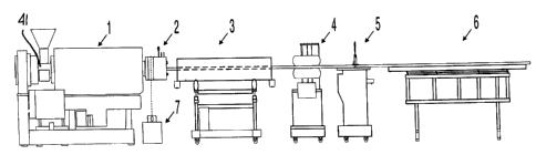
3o FIG. 1 is a simplified side view of an apparatus
constructed in accordance with the present invention for
producing extruded profile of thermoplastic composites with
very high filler content;
FIG. 2 is a detailed cross sectional view of a
35 portion of the apparatus in Figure 1, namely a die assembly
for the production of a non-hollow profile;
CA 02316057 2000-08-16
- 10 -
FIG. 3 is a cross section of a solid profile
extruded employing the die assembly of Figure 2;
FIG. 4 is a detailed cross sectional view of a
portion of the apparatus in Figure 1, namely a die assembly
s for the production of a hollow profile;
FIG. is a vertical cross-section through the mandrel
of the die assembly in Figure 4; and
FIG. 6 is a cross section of a hollow profile
extruded employing the die assembly of Figure 4.
DESCRIPTION OF PREFERRED EMBODIMENTS
Referring to Figure 1, a thermoplastic compound with
40-80% by weight filler content with the remainder 60-20% by
weight thermoplastic resin is continuously extruded using an
extrusion apparatus, for example, a conventional
plasticating extruder 1 (single or twin screw), through a
die assembly 2 which includes a cooled shaper, into a vacuum
or cooling tank 3, followed by a puller conveyor 4, a cut-
off saw 5 and a dump table 6. A lubricant pump 7 is
zo connected to the die assembly.
The compound is prepared a priori in a high speed,
high shear thermokinetic mixer (not shown) which melts the
thermoplastic component of the compound, breaks any
agglomeration of filler particles, and disperses the filler
z5 particles, thus producing a homogenous compound. One or
more additives may be needed to assist the dispersion of the
filler particles, and to improve the bonds between the
filler particles and the polymer.
The compound can be directly fed into a melt-fed
3o extruder, but more commonly the compound is cooled and
shaped into small particles suitable for feeding into a
conventional extruder. In the latter case, the extruder re
melts the compound and pushes the material through the die
assembly. When using cellulose filler, the preferred filler
35 for the process of the invention, an extruder with
ventilation is preferred in order to reduce the moisture
CA 02316057 2000-08-16
- 11 -
level in the molten compound before it enters a die
assembly. The temperatures of the extruder barrel zones
should be low enough to prevent scorching of the cellulosic
filler, and to allow the compound to be solidified before it
s exits the cooled shaper 13, as shown in Figure 2. Typically
the temperatures are between 140°C and 180°C.
The thermoplastic component of the compound may
comprise any thermoplastic polymer (i.e., polyethylene,
polypropylene, polyvinylchloride, polystyrene, etc.). The
~o polymer used depends on the desired properties of the final
product. Thermosetting resins are excluded. Both virgin
and recycled (waste) polymers can be used. For economic
reasons, regrinds of high-density polyethylene (HDPE) from
bottles and film are preferred.
15 In choosing between various grades of a particular
polymer, attention should be paid to the fact that the
molecular weight, and thus, viscosity, of a given grade can
significantly affect the ease of processing. With the
higher molecular weight polymer, a homogeneous compound is
2o more difficult to achieve because of the higher polymer
viscosity. However, a relatively high molecular weight HDPE
(fractional melt HDPE) from waste bottles and film is
preferred due to its abundance and low cost.
The filler component of the compound may be
z5 comprised of either or both reinforcing (high aspect ratio)
and non-reinforcing (low aspect ratio) fillers. Aspect
ratio is defined as the ratio of the length to the effective
diameter. High aspect ratio offers an advantage, i.e.,
higher strength and modulus for the same level of filler
3o content. Inorganic fillers include glass fibres, carbon
fibres, talc, mica, kaolin, calcium carbonate and the like.
Organic fillers include polymeric fibre and cellulose based
filler.
Cellulose based filler is particularly important,
35 and preferred, because of its low cost. It may be derived
from wood/forest and agricultural by-products. Cellulose
CA 02316057 2000-08-16
- 12 -
based filler also offers additional advantages: light
weight, ability to maintain high aspect ratio after
processing in high intensity thermokinetic mixer and low
abrasive properties (thus, extending machine life).
s However, cellulose based filler has several
disadvantages including poor moisture resistance,
biodegradability and poor flame resistance. In addition,
cellulosic fillers are highly hygroscopic. In the raw form,
cellulose fibres can absorb moisture in excess of 40% by
~o weight. Prior to compounding, the cellulosic filler
particles should be dried to less than 10% by weight
moisture content. After compounding and during storage, the
compound can absorb moisture again to an equilibrium level,
which is dependent on the temperature and humidity of the
environment. On a hot and humid day, the moisture level of
the compound can reach as high as 10°s of the weight of the
cellulosic filler. Therefore, pre-drying of the compound
prior to extrusion or the use of ventilated extruder are
recommended to reduce the moisture level of the compound
2o prior to entering the die assembly. For these reasons it is
sometimes desirable to use inorganic fillers to partially or
completely replace the cellulose fibre.
To promote complete and uniform dispersion and
compatibilization of the filler particles with the polymer,
z5 it is recommended to use one or more additives, for example,
dispersing/coupling agents. This agent wets the surface of
the filler particles providing improved dispersion and
adhesion. Carboxylated and maleated polyethylenes have been
found most effective for compounds based on HDPE. Other
3o agents, such as titanates and zirconates may also be used.
Due to the high filler content (40-80o by weight)
and high molecular weight of polymer (such as fractional
melt HDPE) of the compounds used in preferred embodiments of
the process, the mixing process cannot be done in
35 conventional compounding equipment, such as extruders
(single and twin screw) and most high intensity mixers
CA 02316057 2000-08-16
- 13 -
(Henschel, Banbury, etc.). Compounding is ideally conducted
in a high intensity thermokinetic mixer, such as Gelimat*
mixer (Draiswerke), LEX* Mixer (Lex) and K-Mixer*
(Synergistics). It is a semi-batch process, where pre-
y weighed polymer and filler are fed into a chamber with a
blade rotating at a speed up to 3000 RPM.
The heat required to melt the polymer is derived
from the high shearing of the material. In addition, the
high intensity mixing action also reduces the size of
~o oversized particles, separates the particles into fibres
(thus improving reinforcing ability) and mixes the two
components together. Compared to other compounding
equipment, the high intensity thermokinetic mixers produces
a more homogeneous compound, which is necessary for
15 producing products with higher tensile, flexural and impact
strengths and water resistance.
The die assembly used in the preferred process
according to the invention comprises shaping, stabilization
and solidification stages. The first two stages (shaping
zo and stabilization) are commonly applied in regular profile
extrusion, i.e., for thermoplastic compounds with no or low
filler content. The last stage, i.e., the solidification
stage is novel. The solidification stage has been designed
to extrude highly filled thermoplastic compounds into
z5 profiles. Conventional profile extrusion processes employs
a vacuum or cooling tank, which is not directly attached to
the die assembly, to bring molten extrudate into a solid
profile. In the present process, the solidification of
extrudate begins to take place in the last part of the die
3o assembly, i.e., the cooled shaper, which is in direct
contact with the die land, via a thermal heat barrier. The
vacuum/cooling tank is used to further cool the extrudate to
achieve complete solidification and to ease the handling of
the extrudate.
* (Registered Trade Mark)
CA 02316057 2000-08-16
- 14 -
The die shapes the molten compound to the final
shape of the profile. The die must be contoured so that a
balanced and streamlined flow is achieved. Such a contour
can usually be simulated using various polymer flow
simulation packages using finite element and finite
difference calculations for a given compound. For a
compound with such high filler content, the design of the
contour is aimed at minimizing pressure drop across the die,
increasing the throughput and reducing flow instability
~o (imbalance flow, melt fracture and die swell).
The extrudate is stabilized after deformation in the
die. This is done in a die land at a temperature above the
melting/softening point. Thus a more balanced flow is
achieved. Simultaneously, the compound is relaxed from the
stresses resulting from the deformation.
The last part of the die assembly, the cooled
shaper, is set at a low enough temperature so that the
extrudate will be fully or partially solidified in the
cooled shaper. Accordingly, there is a large temperature
2o differential between the end of the die land and the cooled
shaper. The extrudate must not be radially unconstrained at
this point; otherwise radial forces within the heat-softened
mixture will cause expansion and loss of profile shape.
Therefore, an open space between the die land and the cooled
z5 shaper, to limit the heat transfer therebetween, cannot be
arranged. This would cause the unconstrained profile to
swell. It would be impracticable to force the swollen
profile into the cooled shaper. Instead, the cooled shaper
and die land are in direct contact via a thermal barrier.
3o Lubricant is also applied to the surface of the
extrudate as it enters the cooled shaper. This eases the
passage of the extrudate through the cooled shaper. The
solid extrudate leaving the die assembly is then conveyed
through conventional equipment normally used for profile
3s extrusion, e.g., cooling bath, puller, cut-off saw and dump
table.
CA 02316057 2000-08-16
- 15 -
According to the preferred embodiments of the
invention, no significant tension can be applied on to the
extrudate, because molten compound has very low tensile
strength. Tension at the extrudate can cause tensile
failure at the die or die land where the compound is still
hot. Therefore, this process is highly dependent on the
pushing mechanism from the extruder.
Referring to Figure l, the extrusion apparatus 1,
which may be one of many different types of single or twin
1o screw extruders known to those skilled in the art, is used
to melt and convey the plastic composite material through a
passageway in the die assembly 2 shown in detail in Figure
2. The processing conditions in extrusion apparatus 1 are
chosen to ensure that the composite material is completely
melted without causing excessive torque to the extruder
drive and scorching the cellulosic filler. An extruder with
ventilation is recommended to reduce the moisture level in
the compound.
Figure 2 shows a cross-section of a die assembly for
2o producing a non-hollow profile. By way of example, the die
assembly is configured for producing the non-hollow profile
shown in Figure 3. It will be appreciated by someone
skilled in the art that this process applies to a variety of
profiles.
Referring to Figure 2, the die assembly for a non-
hollow profile comprises of a die 10, a land 11, a thermal
barrier 12 and a cooled shaper 13. The conveying action of
the extruder screw located in the extruder barrel forces the
molten compound through a commonly used breaker plate 8 into
so the die 10. This die 10 is so shaped that it will deform
the molten compound from the circular shape of the extruder
barrel into the shape of Figure 3. A cone 9 is used to
improve the flow balance from the breaker plate 8 to the
land 11. The downstream end of the die 10 contacts the
upstream end of a die land 11. The die 10 has a recessed
portion 35 into which a protruding portion 36 on the surface
CA 02316057 2000-08-16
- 16 -
of the die land 11 protrudes, as in a male and female
connection. In the die land 11 the material flow is
stabilized and relaxed after a deformation.
The die land 11 is in contact with a thermal barrier
s 12, which in turn is in contact with the cooled shaper 13.
The thermal barrier 12 has a purposely small cross section
to limit conduction of heat from the land 11 to the cooled
shaper 13. The cooled shaper 13 and die land 11 are
effectively thermally insulated from one another by the
1o thermal barrier 12. Thus the cooled shaper 13 and land 11
can be maintained at different temperatures. The die land
is maintained above the melting point of the profile. The
cooled shaper is below the melting point of the polymer.
Typically the cooled shaper is maintained at a temperature
15 less than 30°C. Thus the temperature drop across the
thermal barrier is as much as 150°C for HDPE-cellulose
composites. The thermal barrier 12 fits into the recess 37
in the cooled shaper 13 and die land 11. The channel 38
through the thermal barrier 12 matches that of the land 11
2o and cooled shaper 13. An oil injection fitting 40 supplies
lubricant to the composite material for the purpose as
described herein. It is pointed out that a lubricant may
also be mixed with the composite material in the mixer and
this lubricant will bleed to the surface of the composite
z5 material and provide the same result. Accordingly, the
lubricant need not be injected at the inlet of the cooled
shaper 13.
The cooled shaper 13 is the last part of the die
assembly. It has a straight channel 39 of the final desired
so dimension of the product. Holes for the cooling system 14
provide intense cooling. The cooled shaper 13 cools the
molten extrudate as quickly as possible so that the
extrudate will be fully or partially solidified before
exiting the cooled shaper. As the molten extrudate flows in
35 the channel 39 of the cooled shaper 13, heat is transferred
from the compound to the metal block of the cooled shaper
CA 02316057 2000-08-16
- 17 -
13, then to a cooling fluid flowing through passageways in
the cooled shaper 14. Various designs of cooling system and
various types of cooling fluid are known to those skilled in
the art.
s While the die land 11 is intended to stabilize the
material flow and relax the material from any residual
stresses and orientation resulted from deformation in the
die 10, the cooled shaper 13 is intended to maintain the
desired shape of the extrudate while it is solidified.
~o Without the cooled shaper 13, not only would the extrudate
melt fracture, it would also swell due to the elastic
property of the polymer and the existence of residual
moisture (especially in the case of cellulosic fillers)
which can act as a foaming agent.
15 The length of the cooled shaper 13 is selected based
on the cooling capability (heat transfer and design) and
production speed. For the same cooling capability, the
length of the cooled shaper 13 is proportional to the
extrusion speed. However, the length of the cooled shaper
20 13 must be limited for economic reasons by improving the
efficiency of heat removal from the extrudate. The cooled
shaper 13 can be cooled using various heat transfer liquids,
including water, directed to flow through channels or
passageways 14 in the cooled shaper metal block near the
2s extrudate channel 39. Cooling techniques are known to
persons skilled in the art, as previously mentioned.
As the extrudate solidifies, the material will
shrink and reduce the pressure it exerts on the surface of
the metal in the shaper 13. As a result, the friction
3o between the solid extrudate and the inner surface of the
cooled shaper is reduced, but not eliminated. Therefore, it
is sometimes necessary to have external lubricant at the
interface to further reduce the friction. Without the
lubricant, the pressure drop across the cooled shaper can
3s exceed the acceptable limit of the extruder. Also the
molten core may flow faster through the channel inside the
CA 02316057 2000-08-16
- 18 -
solid skin formed in the cooled shaper, than the flow of the
solid skin, disturbing the balance of material flow. The
lubricant should be injected as early as possible to allow
good distribution around the profile, but after the
s extrudate is partially cooled to avoid absorption of
lubricant by the cellulosic filler. In this particular
embodiment the external lubricant may be injected through an
injection port located at the thermal barrier (see Figure
4). Various types of lubricant can be used, such as
1o silicone oil, wax, fatty acids, etc.
Referring to Figure 3 the profile produced by the
die assembly of Figure 2 is shown. This cross section shows
a solid skin 15 surrounding a molten core 16. Solid skin 15
is formed near the cooled shaper 13 wall. As the extrudate
1s moves along the cavity in the cooled shaper 13, the solid
skin 15 becomes thicker, while the molten core 16 becomes
thinner. As the extrudate exits the cooled shaper 13 to the
open atmosphere, the solid skin 15 must be thick enough to
provide strength to prevent the molten core 16 from
zo bursting. The pressure that causes bursting comes from two
main sources: the elastic property of the molten
thermoplastic compound after undergoing various stresses and
deformation (memory effect) and the presence of moisture in
the cellulose which will act as foaming agent at an elevated
z5 temperature. Therefore, material formulation and
preparation can affect the ease of processing. For example,
decreasing the thermoplastic component in the compound or
using thermoplastics with low elastic property can reduce
the overall elastic property of the compound. The present
30 process works well with thermoplastic compound with filler
content in excess of 40% by weight. In addition, reducing
the moisture content in the compound, preferably below 10%
of the weight of the cellulosic filler, is also beneficial
to the process.
35 Figure 4 shows a cross section of a specific
embodiment of the present invention for the production of a
CA 02316057 2000-08-16
- 19 -
hollow profile, as shown in Figure 6. Referring to figure
4, the compound enters the breaker plate 21 from the screw
tip. The breaker plate 21 homogenizes the melt. The
polymer then enters the channel formed by the annulus
s between the die 17 and the mandrel 20. The die 17 is heated
to a temperature above the softening point of the composite.
It should be noted that in this embodiment of the present
invention the last length of the die 17 acts as the die land
17' . It is of constant cross-section to allow the material
~o to relax. In effect the die 17 and the die land 17' are
integral.
The mandrel 20 in this region is not heated but is
maintained at a temperature above the softening point of the
compound by conductive heat transfer from the breaker plate
and the die. From this point the composite converges to the
end of the channel to the thermal barrier member 19 and the
cooled shaper 18. The cooled shaper 18 contains holes for
cooling system 24, which traverse the perimeter of the
cooled shaper. The thermal barrier member 19 and the cooled
zo shaper 18 are of the same design and purpose as those
described for the solid profile above. For the hollow
profile the mandrel 20 is cooled in the section in the
cooled shaper 18. Cooling fluid is supplied to the mandrel
20 by pipe 23. The cooling system in the mandrel 20 is such
z5 that the cooling water is insulated from the mandrel 20 in
the section of the die but cools the mandrel 20 in the
section 20' of the cooling shaper. Thus the hollow profile
can be cooled on both the inside and outside to create a
solid skin. Lubricant is supplied by the oil injection
3o fitting 22.
The cooling system of the mandrel is best
illustrated by Figure 5. This figure shows a section of the
mandrel 25 and cooling system. Cooling fluid enters the
cooling system for the outer leg 31 in the cooling end 26.
35 The fluid flows through the center pipe of the cooling rod
29. At the end of the cooling rod 29 the fluid exits the
CA 02316057 2000-08-16
- 20 -
center pipe radially and travels back to the cooling end 26.
In the section of the cooling shaper the cooling fluid is in
intimate contact with the mandrel, thus cooling the
composite. The fluid is insulated from the mandrel in the
s section of the die by an additional pipe. A thermal
gradient exists such that the mandrel is below the softening
point of the composite in the area of the cooled shaper and
above the softening point of the composite in the area of
the die.
~o The cooling fluid enters the cooling system for the
inner leg 30 via a cooling insert 27. The fluid travels in
a pipe of the cooling subassembly 28 insulated from the
mandrel to a point where it is forced out radially and comes
into contact with the mandrel. The fluid travels to the end
of the mandrel and then back to the cooling insert 27 in a
similar assembly in the mirrored half of the inner leg (not
shown).
Figure 6 shows the hollow profile produced by the
die assembly of Figures 4 and 5. Figure 6 illustrates the
zo solid skin 32 encompassing the molten core 33. The solid
skin 32 grows in thickness as the composite passes through
the cooled shaper. At the exit of the shaper the solid skin
32 must be of sufficient thickness to resist deformation.
In the vacuum sizer the profile is further cooled so that
z5 the entire profile is solid.
The overall design of the die assembly is aimed at
obtaining balanced flow (which is very critical for non-
symmetrical profiles), reducing pressure drop across the die
assembly and minimizing surface defects, such as shark skin,
3o melt fracture and extrudate swell. Considering the high
melt viscosity of the compound, such defects are difficult
to avoid in a conventional profile extrusion.
The melt viscosity of a compound with 50% by weight
of fractional melt HDPE and 50o by weight of cellulosic
35 filler at a shear rate of 100 s 1 and 180°C is 7000 Pa-s, as
compared to that of the same HDPE at the same conditions is
CA 02316057 2000-08-16
- 21 -
450 Pa-s. For higher filler content, the difference will be
even higher (more than two orders of magnitude). Computer
simulation and actual experimentation prove that such a
compound cannot be extruded in a conventional way, i.e.,
above the melting point, without surface defects. However,
the process and apparatus of the present invention can be
used to produce a smooth extrudate with controlled
dimensions.
~o EXAMPLES
The following examples further illustrate the
invention; however, they are not meant to limit the scope of
the possible applications of the described invention.
Example 1
This example describes the production of the non-
hollow profile of Figure 3.
The thermoplastic compound used in this sample
zo comprised 59 parts by weight fractional melt HDPE (MI = 0.4)
from milk bottles with no colour added (natural), 40 parts
by weight of ground wood waste/saw dust (20-80 mesh) and 1
part by weight of maleated polyethylene (Fusabond MB 226D,
Dupont) as a coupling agent. The apparatus used in this
z5 example was a 4.5 inch single screw vented extruder (L/D
ratio 32:1) with a die assembly (Figure 2) with proper
dimension to produce a non-hollow profile (Figure 3).
The processing conditions were as follows:
(i) Setting for the extruder barrel temperature
so control zones (upstream end to downstream end):
165, 165, 160, 160, 155, 155°C.
(ii) Setting for die assembly temperature control zones
(die, die land, cooled shaper): 145, 140, 20°C.
The product has the following flexural strength and
35 modulus: 48 MPa and 2.8 GPa.
CA 02316057 2000-08-16
- 22 -
Exaatple 2
This example describes the production of a non-
hollow corrugated profile as in example 1.
The thermoplastic compound used in this example is
s similar to example 1 except that the composition is 48 parts
by weight of the same HDPE, 50 parts by weight of saw dust
and 2 part by weight of maleated polyethylene. The same
apparatus and processing conditions were used in this
example as in Example 1. The product has the following
~o flexural strength and modulus: 60 MPa and 3.5 GPa.
Example 3
This example describes the production of a non-
hollow profile as in example 1.
15 The thermoplastic compound used in this example is
similar to example 1 except that the composition is 38 parts
by weight of the same HDPE, 60 parts by weight of saw dust
and 2 part by weight of maleated polyethylene. The same
apparatus and processing conditions were used in this
zo example as in Example 1. The product has the following
flexural strength and modulus: 69 MPa and 4.5 GPa.
Example 4
This example describes the production of the hollow
2s profile of Figure 6.
The thermoplastic compound used in this sample
comprised 59 parts by weight fractional melt HDPE (MI - 0.4)
from milk bottles with no colour added (natural), 40 parts
by weight ground wood waste/saw dust (20-80 mesh) and 1 part
so by weight of maleated polyethylene (Fusabond MB 226D,
Dupont) as a coupling agent. The apparatus used in this
example was a 4.5 inch single screw vented extruder (L/D
ratio 32:1) with a die assembly (Figure 4) with proper
dimension to produce a non-hollow profile (Figure 6).
35 The processing conditions were as follows:
CA 02316057 2000-08-16
- 23 -
(i) Setting for the extruder barrel temperature
control zones (upstream end to downstream end):
165, 165, 160, 160, 155, 155°C.
(ii) Setting for die assembly temperature control zones
s (die, mandrel, cooled shaper): 155, 65, 20°C.
The product has the following flexural strength and
modulus: 47 MPa and 2.8 GPa.
Example 5
~o This example describes the production of a hollow
profile as in example 4.
The thermoplastic compound used in this example is
similar to example 4 except that the composition is 38 parts
by weight of the same HDPE, 60 parts by weight of saw dust
~s and 2 part by weight of maleated polyethylene. The same
apparatus and processing conditions were used in this
example as in Example 4. The product has the following
flexural strength and modulus: 68 MPa and 4.3 GPa.