Note: Descriptions are shown in the official language in which they were submitted.
CA 02316555 2000-08-21
TITLE
DEVICE FOR ABSORBING VIBRATION OF RAIL
BACKGROUND OF THE INVEH3'ION
1. Field of the Invention
The present invention relates to a device for
absorbing the vibration of the rail which is capable of
protecting the train, the concrete roadbed. and the
buildings near the railroad from the vibration and the shock
generated when the train travels on the rail and which is
capable of improving the passenger's feeling of the boarding
of the train through the enhancement of the silence in
travel of the train.
2. Description of the Prior Art
In subway, it is a general tendency that the concrete
roadbed is substituted for the gravel roadbed for the
purpose of accomplishing the convenience of maintenance and
preventing the environment pollution.
Since the rail is laid on the concrete roadbed in the
subway of the city, the effect of absorbing the vibration is
inferior to that obtained from the gravel roadbed of the
prior art. Consequently, there are generated noises beyond
the critical values between the rail and the wheel of the
running train. As a result, there occur several problems,
' CA 02316555 2000-08-21
such as difficulty in conversation between the passengers,
inconvenience in use of the mobile phone, several bad
effects applied to the structure, the train, rail, etc.
Fig. 1 shows a device for absorbing the vibration of
the rail according to the prior art which is installed in
the railway bridge, the subway, etc. As shown in Fig. 1, a
thin support plate B is laid on a rail tie A. A rubber plate
C is laid on the thin support plate H . A lower plate D around
the rubber plate C is mounted on the roadbed by means of an
anchor bolt E. A rail G is laid on a upper plate F. The rail
G is fixed to the upper plate F by means of an insulating
plate H, a cover plate I, and a rail fixing member J.
When the train passes on the rail, noise and vibration
are generated. These noise and vibration are absorbed by
virtue of the rubber plate of the upper plate D. Molten
rubber is poured from the top of the lower plate L, and then
the upper plate D is pressed against th~s bottom of the lower
plate, whereby the rubber is squeezed between the lower
plate and the upper plate. In this way, the device for
absorbing the vibration of the rail according to the prior
art is produced.
However, the costs for manufacturing the device for
absorbing the vibration according to the prior art are very
heavy, and the costs and the times necessary for replacing
the device for absorbing the vibration of the rail according
-2-
CA 02316555 2000-08-21
to the prior art since the entire device is substituted if
an abnormal condition of the vibration absorbing rubber is
detected.
Furthermore, even if the elasticity of the rubber
plate 3 is deteriorate a little bit, the shock generated
from the rail may be transmitted directly to the upper plate
L, thereby the traffic safety being endangered.
SUI~iARY OF THE INVENTION
Accordingly, it is an object of the present invention
is to provide a device for absorbing the vibration of the
rail by which the efficiency for absorbing the vibration of
the rail is improved, the replacement of the vibration
absorbing pad is easy the maintenance of the railroad is
convenient the thrust of the rail is prevented and thus
the safe train service is accomplished.
The foregoing object is accomplished in one embodiment
by providing a device for absorbing the vibration of the
rail comprising: a support plate having an anchor hole for a
stay anchor formed around one of the diagonally opposite
corners; a thick vibration absorbing pad having a anchor
hole for the stay anchor formed at the position
corresponding to that of the anchor hole; a support plate
for the rail having an anchor tube which is projected
upwardly on the support plate for rail with an anchor hole
-3-
CA 02316555 2000-08-21
formed therein, and an fixing hole formed at the anchor
tube, said fixing hole being formed through the support
plate for the rail in parallel with the direction in which
the rail is laid; a stay anchor inserted into the anchor
hole of the support plate, the anchor hole of the vibration
absorbing pad and the anchor hole of the support plate for
the rail for stabilizing the connection therebetween; a
fixing nut engaged with the thread provided at the upper end
of the stay anchor; and a cap for protecting the fixing nut
engaged with the stay anchor.
The present invention also provides a vibration
absorbing pad for repair of the rail which is divided into a
main body and a corner portion by the means of the boundary
line which is cut diagonally at the inward portion of the
center of the anchor hole.
BRIEF DESCRIPTION OF THE DRAWINGS
The preferred embodiment of the present invention will
now be described by way of example with reference to the
accompanying drawings in which:
Fig. i is a cross-sectional view of a rail with a
device for absorbing the vibration of the rail according to
the prior art:
Fig. 2 is an exploded view of a device for absorbing
the vibzation of a rail according to the present invention;
-4-
CA 02316555 2000-08-21
Fig. 3 is a plan view of the rail with the device for
absorbing the vibration of the rail according to the present
invention;
Fig. 4 is a cross-sectional view taken along the line A
- A of Fig . 3; and
Fig. 5 is a perspective view of a replaceable vibration
absorbing pad according to the present invention.
DETAILED DESCRIPTION OF THE PREF~RF.D EMBODIMENT
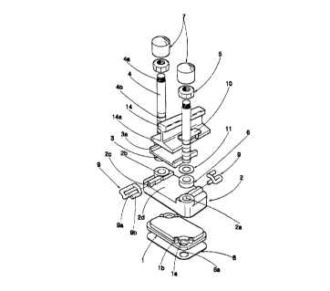
As shown in Fig.2, a device for absorbing the vibration
of a rail according to the present invention includes a
vibration absorbing pad i, a support plate for the rail 2, a
rail pad 3, a stay anchor 4, a fixing nut 5, a packing 6, and
a cap 7.
The vibration absorbing pad 1 is mounted on a
well-known support plate 8 which is arranged on the location
where the rail is laid at a concrete roadbed, for
accomplishing a secondary vibration absorbing function to
the rail. The vibration absorbing pad 1 is in the form of a
rectangle with the a lateral width being longer than a
longitudinal width, which is made of thick rubber or
urethane with low elasticity. The vibration absorbing pad 1
is provided at the two corners opposite diagonally with
anchor holes la through which the stay anchor 4 is inserted.
Also, a pair of positioning set pins lb is provided at
-5-
CA 02316555 2000-08-21
predetermined intervals around each of the anchor holes la.
The positioning set pins ib are inserted into pin holes
formed around an anchor holes at the lower surface of the
support plate for the rail 2, for reinforcing its stability
on the stay anchor 4 and its engagement with the support
plate for the rail 2.
The support plate for the rail 2 is provided to the
support the rail which is laid on the concrete railroad
substantially. The support plate for the rail 2 is made of
metal, which is of the same type and also of the same area
as the absorbing pad 1. And the support plate for the rail 2
is provided at the locations corresponding to that of the
anchor holes is of the absorbing pad 1 with anchor tubes 2b
which is projected upwardly on the support plate for rail 2.
Each of the anchor tubes 2b has an anchor hole 2a formed
therein. Near the opposite sides of seats for the rail pads
2d which is provided on the support plate for the rail 2 are
formed fixing holes 2c, which are formed through the support
plate for the rail 2 in parallel with the direction in which
the rail is laid.
The rail pad 3 is provided to accomplish a primary
vibration absorbing function, which is made of thick rubber
or urethane with low elasticity. The rail pad 3 is fitted
into the seats for the rail pads 2d of the support plate of
the rail 2. The rail pad 3 is provided at the opposite ends
-6-
CA 02316555 2000-08-21
thereof with low-cut portions 3a for protecting the sides of
the lower portions of the rail, which is of the width
thicker than that of the vibration absorbing pad i .
The stay anchor 4 is stuck in the concrete roadbed,
which is inserted into the anchor hole ea of the support
plate e, the anchor hole is of the vibration absorbing pad i
and the anchor hole 2a of the support plate for the rail 2
for stabilizing the connection thereb~etween. In addition,
the stay anchor 4 acts as a guiding bar which is capable of
guiding smoothly the rail pad 3, the support plate for the
rail 2 and the vibration absorbing pad 1 upward and downward
as the rail pad 3, the support plate for the rail 2 and the
vibration absorbing pad 1 are pressed down when the train
passes on the rail, and as the rail pad 3, the support plate
for the rail 2 and the vibration absorbing pad Z are
returned to their positions upwardly after the dynamic load
of the train disappears . The stay anchor 4 is provided at
the upper end thereof with a thread 4a, and at the lower end
thereof with an anchor portion 4b which is inserted into the
anchor hole formed perpendicular to the concrete roadbed.
Strong adhesives are filled the gap between the anchor
portion 4b and the anchor hole so that the anchor portion 4b
is fixedly mounted into the concrete roadbed.
The fixing nut 5 is engaged with the thread 4a provided
at the upper end of the stay anchor 4, for preventing the
CA 02316555 2000-08-21
support plate for the rail 2, the vibration absorbing pad 1
a.nd the support plate 8 from leaving their positions
respectively.
The packing 6 is provided to prevent the physical
contact between the upper surface of the anchor hole 2a of
the support plate for the rail 2 and the lower surface of the
fixing nut 5 and to maintain the tightness of the support
plate for the rail 2 when the support plate 8, the vibration
absorbing pad 1 and the support plate for the rail 2 are
arranged above and below by means of the stay anchor 4
fixedly mounted in the concrete roadbed, and thereafter the
f fixing nut 5 is engaged with the upper end of the stay anchor
4. The packing 6 is made of rubber or urethane with low
elasticity.
Alternatively, a spring may be used instead of the
packing 6.
The cap 7 is provided to protect the fazing nut 5
engaged with the stay anchor 4. The cap 7 is provided at the
inner circumference thereof coming down by the thickness of
the edge of a washer ii from the top with a locking jav~ 7a as
shown in Fig. 2. which is provided to prevent the cap 7 from
coming off unless the cap is forced to separate from the
fixing nut 5.
A rail ffixing member 9 and a insulating block 10, which
are not mentioned in the aforesaid description of the
-8-
CA 02316555 2000-08-21
constructions, are of the same constructions as those of the
prior art. And the reference numeral 11 indicates a washer
provided on the packing 6.
Fig. 3 and Fig. 4 are a plan view and a cross-sectional
view of the rail with the device for absorbing the vibration
of the rail according to the present invention,
respectively. A vertical anchor hole 12a is formed in the
concrete roadbed 12 on the concentric line with the anchor
holes 8a, is and 2a, in which strong adhesives 13 is filled.
And then, the stay anchor 4 is inserted into the vertical
anchor hole 12a. The stay anchor 4 ars fixedly mounted in
the vertical anchor hole 12a after the strong adhesives is
hardened. The anchor hole 12a is of the depth sufficient to
depress the shaking of the support plate for the rail 2
insofar as the dynamic load of the train is not activated
through the depression of the vibration absorbing pad 1 and
the packiag 6 caused by the pressure of the engagement
therewith when the fixing nut 5 is completely tightened
of ter the support plate 8, the vibration absorbing pad 1,
the support plate for the rail 2, the packing 6 and the
washer 11 are f ixed into the exposed portions of the stay
anchor 4 on the concrete roadbed 12 uad~er the condition that
the stay anchor 4 is mounted normally in the concrete
roadbed 12.
After the stay anchor 4 is mounted, the stay anchor 4
_g_
CA 02316555 2000-08-21
is inserted into the anchor hole 8a of the support plate 8,
the anchor hole la of the vibration absorbing pad 1 and the
anchor hole 2a of the support plate for the rail 2.
Thereafter, The packing 6 and the waster 11 are arranged one
after another on the anchor tube 2b of the support plate for
the rail 2. At this time, the total heights of the support
plate e, the vibration absorbing pad 1, the support plate
for the rail 2, the packing 6 and the washer 11 are higher
than the lower boundary line of the thread 4 of the stay
anchor 4. As the heights of the vibration absorbing pad i
and the packing 6 are reduced resiliently by means of the
engagement of the fixing nut 5, however, the support plate
for the rail 2 is depressed at the suitable pressure,
thereby the shaking of the support plate for the rail 2
being prevented.
At this time, any error in the height of the concrete
roadbed may be compensated by adjusting the thickness of the
support plate 8.
After the fixing nut 5 is completely engaged, the rail
pad 3 is placed firmly on the seats for the rail pads 2d of
the support plate for the rail 2. At this time, the rail pad
3 is in contact with the opposite sides of the support plate
for the rail 2 by the low-cut portions 3a of the rail pad 3.
The rail 14 is laid on the rail pad 3. Then, the
insulating block 10 is arranged on the flange 14a of the
-10-
CA 02316555 2000-08-21
rail Z4, on which the pressing portion is placed.
Thereafter, the fixing end 9a of the rail fixing member 9 is
inserted by force into the fixing hole 2c of the support
plate for the rail 2. As a result, the rail 14 is stabilized
by the pressing portion 9b applying the strong force to the
upper surface of the insulating block 10.
Finally, the cap 7 is applied to the fixing nut 5 to
protect the fixing nut 5 and provide the good appearance. In
addition, the cap 7 can not come off from the fixing nut 5
easily by virtue of the locking jaw 7a. Consequently, the
f fixing nut 5 can not be released eas ily .
The vibration absorbing pad 1 as mentioned above is
used for the initial construction of the rail, while a
vibration absorbing pad 5 as shown in Fig. 5 is used for
repair of the rail. When it is required to replace the used
vibration absorbing pad i whose endurance term expired with
a new vibration absorbing pad, it is necessary for
unfastening the fixing nut 5, and then pulling out the
support plate for the rail 2 in order to the replace the
vibration absorbing pad 2. However, such a replacement
requires excessive costs, takes a plenty of time, and is
very inconvenient.
In order to eliminate the drawbacks caused in
replacement of the rail pad, it is required to provide a
novel method for replacing only the vibration absorbing pad
_ 11 _
CA 02316555 2000-08-21
1 easily without pulling out the other elements under the
condition that the rail 14 is laid on the concrete roadbed.
The vibration absorbing pad 1-i and 1-2 for repair as shown
in Fig. 5 eliminates the drawbacks as mentioned above. The
vibration absorbing pad 1-1 and 1-2 are divided into the
main body 1-1 and the corner portion 1-2 by the means of the
boundary line which is cut linearly at the side edge and the
front edge or, at the side edge and the rear edge such that
the it passes the location spaced inwardly from the set pins
ib .
Nhen it is required to replace the vibration absorbing
pad 1 with the replaceable vibration absorbing pad 1-1 and
1-2, a few rail fixing members of the device for absorbing
vibration of the rail are pulled out from the fixing holes
of the support plate for the rail 2 to lift up the rail to be
replaced. The cap 7 is released from the rail to be
replaced, and then the fixing nut 5 is loosened properly to
remove the vibration absorbing pad i. Next, the support
plate for the rail 2 is lifted up by means of a lever or s
hydraulic jack in order to obtain space necessary to remove
the vibration absorbing pad 1 and insert a new vibration
absorbing pad. Thereafter, the used vibration absorbing pad
1 is removed, the main body of the nevr vibration absorbing
pad 1-1 is inserted from the lower side surface of the
support plate for the rail 2, the corner portion of the new
-~a-
CA 02316555 2000-08-21
vibration absorbing pad 1-2 is inserted from the left and
the right, and then the rail is returned to the original
position. The new vibration absorbing pad 1-1 and Z-2 is not
come off by means of the set pins ib.
Regardless of the vibration absorbing pads 1 and 1-1,
in case that the rail 14 is laid as sho~~n in Fig. 2, when the
train passes on the rail, the dynamic load of the train is
absorbed first at the rail pad 3 before it is transmitted to
the support plate for the rail 2. However, the unabsorbed
dynamic load is transmitted to the support plate for the
rail 2. The support plate for the rail ~ is lowered a little
bit under the guidance of the stay anchor 4 by virtue of the
dynamic load transmitted to the support plate for the rail
2. The vibration absorbing pads i and 1-i are depressed by
the lowered support plate for the rail 2 to accomplish the
secondary absorbing function.
Upon accomplishment of the secondary absorbing, the
vibration caused by the dynamic load of the train is almost
never transmitted to the concrete roadbed i2. As soon as the
train is passed, the support plate for the rail 2 is
returned upwardly by virtue of the force of the restitution
of the vibration absorbing pad 1. As a result, the rain 1~ is
returned to the original position by virtue of the force of
the restitution of the vibration absorbing pad as mentioned
above and the force of the restitution of the rail pad 3.
-13-
CA 02316555 2000-08-21
As mentioned above, with the device for absorbing the
vibration of the rail, the up-and-down motion thereof is
carried out freely as the support plate for the rail 2 is
lowered dowawardly under the guidance of the stay anchor 4
when it is subject to the dynamic load and the support plate
for the rail 2 is returned upwardly under the guidance of
the stay anchor 4 when the dynamic load transmitted to the
support plate for the rail 2 disappears, whereas the front
and rear motion as well as the right and left motion, and
the unequal subsidence thereof are prevented completely. As
a result, there is no possibility of derailment of the
train.
The device for absorbing the vibration of the rail
according to the prior art uses hour small anchor bolts (~
26 1~I), which are replaced frequently due to corroEion
thereof at the damp weather. In contrast, the device for
absorbing the vibration of the rail according to the present
invention has an excellent durability since the device for
the absorbing the vibration uses two larger anchor bolts (~
40 ~) .
Particularly, if the thickness of the vibration
absorbing pad. it is possible to maaamize the vibration
absorbing effect since the support plate for the rail is
stabilized in engagement with the stay anchor. In addition,
it is possible to improve the durability of the concrete
-14-
CA 02316555 2000-08-21
roadbed and the train, and to improve the passengers
feeling of the boarding of the train.
Also, with the vibration absorbing pad (Fig. 5)
comprising the main body and the corner portion which
includes a portion of the anchor hole, it is convenient to
replace the vibration absorbing pad when it is antiquated or
damaged, it is easy to maintain the vibration absorbing pad,
and it is possible to reduce the costs including the
replacement time for the vibration absorbing pad and the
personnel expenses.
Furthermore, it is possible to form the good
appearance, and to reduce the size and the weight as
compared to the device for absorbing the vibration of the
rail according to the prior art since only the cap and the
fail fixing member are exposed.
-15-