Note: Descriptions are shown in the official language in which they were submitted.
CA 02316608 2000-08-24
SURGE SUPPRESSION APPARATUS INCORPORATING A
PRESSURE REGULATION ASSEMBLY
Technical Field
This invention relates to a surge suppression apparatus incorporating a
pressure regulation assembly. More particularly, but not exclusively, the
invention relates to a surge suppression apparatus having means for
regulating the pressure of a pressurised gas therein.
Background Art
It is known to use a reciprocating pump for the pumping of a liquid in a
delivery system. Such reciprocating pumps do not have a smooth output and
a pressure drop occurs in the liquid during the reversal of the pump stroke.
Surge suppression apparatus is used to negate the drop in pressure and
thereby improve the constancy of the liquid output pressure.
A known surge suppression apparatus comprises a passive surge bottle which
is basically a captive (static) gas volume acting as a pressure reservoir. A
passive surge bottle inevitably loses pressure in use and thus there is a
necessity for the periodic recharging of the bottle with compressed gas and
the subsequent, associated recalibration of the system utilising the bottle.
European Patent Application No. EP 0 707 173 A1 discloses a surge
suppression apparatus incorporating an active pressure regulation
arrangement which recharges the gas pressure therein automatically. Such an
active pressure regulation arrangement in a surge suppressor removes the
necessity for the periodic recharging of a passive surge bottle, but the
apparatus disclosed in EP 0 707 173 A 1 tends to be bulky and inconvenient in
CA 02316608 2003-08-06
'F
~,.~,~,.~3t"~'~~~:#~'~'. ~~~#s~ ~:~'~?#~a~s iP~#.~W'~~~.#.~3i'#. ~~'.~~ ~;E.'t
~?~..~~,~#~~. a3, 53.3~'~~' ~a~#.~~'i~'s~z~ils~X~
~~~~ ~x~~~~~~ ~~' ~~ ~~~~~~~~
~#-#~~~~~~~~~~, ~ s;~~;~,a~#~~Sz°~° ~3a~t~~c~ ~~~~~. ~~~v~
>~a~s~ :~~:c:~~~:~;:~ ~~~~~~:.;~~.~z~~~.~~~ ~5~~ a, ~~.<~~s~.~f~~~s~~o ~.
~~_~:~~,~~xt~~~~~~ f~~~~3°3~~:~° ~~ ~.~~:~ ~'~:~~i~~~;i~~~; taw
~~~~~~~~r~~~~~~ ~~ t~~~ ~~~~~~:~~~;~~~~ i~~ z~~~a~~~~.~ ~~ a~
~~e~.s~~ s~~~.~'~~~~~~~~~I ~»~:3~~~;:c:~ ~.1~~, f~~~~~t. ~~aci s~,~.~~ ~~~~.~s-
~~~~x~~.~~, ~~~~ ~~~:~,~~;.xw~~.~~
.~~sI.IF~~~w ~~ir~~ ~-#~E»>si:~~~. ~°~:~~~~:~v>~ ~v~ ~W~ ~:~.~~~r~~>~~
~~,~~:~~ 4~~~ ~ ~.~~A#~.~ ~v~-- ~~~S~r~~~w~~ 4:~~~#~~~;~~~
~~c~ o~ '~3~"i~, v<#.~."S'>':;' ~.$"s ~~~i.~F'°~'#."#.~.~'e$'~3~
~.s~.s.4: 'w'.,~.~ ~'<'~.~'#>.4~..s~'° s.~3F~
~'9~';~c3'~"~."v'~'.~°~54: ''~3~~ :3,
'w'CDxs'.s_~~~l'~.~.~lxi::c'%.~t.'~~k$"f
~~<~~~~~ lse~.v~,w~~ t~a~. ~~:n;~~~~~~ :~~-~~~~~~~~:~ ~.#~a~~ _~ ~s~~ i~~~~~.
~~~~~ ~~~:~~~~ ta~~. ~~.i~v~s~~~~
~~~r~a~.~#.~. t3~~ <~ ~~~:~~.r~~~ ~e ~~~>~.~ ~t3~- ~e~:~r~~ia~~x~~ ~~:u ~~:as~-
~~#.~~ ~~ ~t~t~~~~is~ ~t~~ ;~
s~~~,,~~~~~~~.~;~~ ~a:~~~~4e~~~~ ~.~: ~:~s~~.~ X53 ~~~x#:~:::~~:~: ~~~;:.
~~~~~>~r~~~~~~E a~~ ~.~~ ~:i~4~~~ ~w~> <~ ~:::r4~;~~~~
~~~r~s~~;s~ ~'~~~~~~~ ~~~~:~s~~i: ~t~ ~.1~~: ~c~.~#~~Ex s~~~#-~;.~~~~~~~~r.
~~~~~~%~~.~.~x~~v'~ ~,c ~,ah A.j.t:~<~~;:~.~:a~~. ~,~ ~~~>, ~~35.~i~-~o~.,
~~~,~ ~~~.~~~~~~~~~ ~~~~~x~s=~;~~ i:~ ~:~~~,~~~~~ ~~
~-.~~~ ~~i.;~Lf~~~°~~;~v~.~
~~>~ L~~.~.~.'~c~. ~~~g:~ ;:~~ <~z ~:~3 ~~~~.~~ ~ ~a;~.~vf~~~~z~ ~~1~~:,~ ~~,~
~~~~~~~~.a~~; ø.~~a~~~~~~~~ .~>:i~.~ ~~a;
~:;~~~~:~r~~~~~v~= ~;~~~ ~:~~.a~j~_~ ~;~~~ ~:~ ~~~ar~- f~~ ~ ~~#a.~~~~~~
~~~~~~~~ ~:~~.~~:. ;.~~~~~~~ st~~ic
~a.~r~:~ a:~~ ~~~~ ~:~rz~: a~.~ s~~;~-~~~~~ ~~<~a~~;~.w,
CA 02316608 2000-08-24
-3-
Preferably said first and second valves are so arranged that there is a range
of
movement of the diaphragm on opposite side of a central equilibrium position
in which neither valve is operated so as to define a "dead band" in the
operation of the apparatus.
Conveniently said diaphragm follower includes a disc of larger diameter than
the shaft and smaller diameter than the diaphragm engaging the diaphragm
and controlling flexure thereof.
Brief Description of the Drawings
The invention will now be described, by way of example only, with reference
to the accompanying drawings in which:
Figure 1 is a sectional view of a surge suppressor incorporating a pressure
regulation apparatus according to the present invention; and
Figure 2 is a sectional view of a surge suppression apparatus according to the
present invention in an equilibrium configuration;
Figure 3 and Figure 4 are sectional views of the apparatus of Figure 2 in
alternative non-equilibrium configurations; and Figure 5 is across sectional
view illustrating a desirable modification.
Description of the Preferred Embodiments
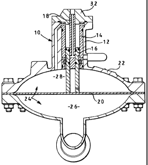
A surge suppression apparatus 10 includes a circular housing 12, a circular
cylindrical sleeve 14, a follower shaft 16, in the form of a sleeve, a centre
feed shaft 18 and a flexible diaphragm 20.
CA 02316608 2000-08-24
-4-
In the embodiment shown in the Figures the housing 12 is an integral part of
a surge suppressor body 22 and the diaphragm 20 divides a chamber 24
thereof into first and second sub-chambers 26, 28.
The housing 12 comprises a substantially cylindrical hollow body part 30 and
a substantially annular cap 32.
A wall 34 of the body part 30 is of differing thickness about its
circumference such that the longitudinal axis of a cavity 36, defined by the
wall 34, is not coincident with the longitudinal axis of the body part 30. The
internal surface of the wall 34 has an outwardly extending ledge 38 at the
upper end thereof. A passageway 40 extends through the thickest part of the
wall 34 from the second sub-chamber 28, communicating with the cavity 36
above the ledge 38. A passageway 41 extends through the narrowest part of
the wall 34 near to the surge suppressor body 22. A top surface 44 of the
body part 30 engages an annular base 46 of the cap 32, a ring seal 52 being
seated therebetween.
A small chamfered annular projection 54 depends from the base 46 of the cap
32 and the cap 32 has a central longitudinal bore 49 therethrough, the bore 49
having a step 56 therein, the lower portion of the bore 49 being wider than
the upper portion thereof.
The cylindrical sleeve 14 has an outer surface 58 and an inner surface 60. A
lip 62 projects radially from the outer surface 58 at a level near the upper
end
of the sleeve 14. A series of passageways 63 extend radially between the
CA 02316608 2000-08-24
-5-
inner and outer surfaces 60, 58 of the sleeve 14 above the level of the lip
62.
The outer surface 58 has a first circumferentially extending groove 64 which
is slightly below the level of the lip 62 and accommodates a first annular
ring
seal 66 and a second circumferentially extending groove 68 near to the
bottom of the sleeve which accommodates a second annular ring seal 70. An
axial elongate gallery 72 is formed on the outer surface 58 extending
substantially between the first and second grooves 64, 68. A plurality of
circumferentially spaced passages 74 extend radially through the sleeve 14
from near the base of the gallery 72. A third circumferentially extending
groove 76 is formed in the inner surface 60 of the sleeve 14 at a level
between the passages 74 and the second groove 68 so as to accommodate a
first radial lip seal 78.
The follower shaft 16 has a head portion 80 and a body portion 82, the body
portion 82 having a smaller diameter than the head portion 80. The head
portion 80 has a first circumferentially extending groove 86 in the outer
surface thereof provided so as to accommodate a second radial lip seal 88. A
second circumferentially extending groove 90 in the inner surface of the
follower shaft 16, slightly below the first groove 86, accommodates a third
radial lip seal 92. Immediately below the head portion 80 there is a shallow
annular recess 94 in the body portion 80. A third circumferentially extending
groove 96 is formed in the inner surface of the follower shaft 16 immediately
below the recess 94 to accommodate a fourth radial lip seal 98. A radially
extending bore 100 is provided towards the lower end of the body portion 82.
The centre feed shaft 18 has an circumferential groove 102 near the lower
end thereof, a cross-drilling 104 which communicates with said groove 102
CA 02316608 2000-08-24
-6-
and a central longitudinal bore 106 extending from the top of the centre feed
shaft 18, intersecting the drilling 104.
In use, the cylindrical sleeve 14 is fixed inside the housing 12 coaxial
therewith, the underside of the lip 62 engaging the upper surface of the ledge
38. The centre feed shaft 18 is fixed in the cap 32 such that the upper end of
the centre feed shaft 18 abuts the step 56 and the bore 49 and the drilling
104
are coaxial. The lower end of the centre feed shaft 18 is aligned with the
lower end of the sleeve 14 by the step 54 locating on the inner surface 60.
The follower shaft 16 is slidably received by the inner wall 60 of the sleeve
14 and in turn slidably receives the centre feed shaft 18. The lower end of
the follower shaft 16 rests on the diaphragm 20 such that shaft 16 moves with
the diaphragm relative to the sleeve 14 and the feed shaft 18, in response to
flexure of the diaphragm 20.
The passageway 40 and the passageways 63 provide communication between
the second sub-chamber 28 and a chamber 108 defined between the head
portion 80 of the follower shaft 16 and the projection 54 so as to maintain an
equal pressure therein. As the pressures in the second sub-chamber 28 and
the chamber 108 are equal the vertical forces exerted on the head portion 80
and body portion 82 of the follower shaft 16 are determined by their effective
areas. As the head portion 80 has a larger diameter than the body portion 82
the head portion 80 presents a larger effective area than the body portion 82.
Thus there is a net downward force exerted upon the follower shaft 16
maintaining it in contact with the diaphragm 20.
CA 02316608 2000-08-24
In use, compressed air is supplied to the centre feed shaft 18 via the
longitudinal bore 49 through the cap 32 at a pressure in excess of the
pressure of the liquid medium present in the sub-chamber 26 in use.
Figure 2, shows the surge suppression apparatus 10 in an equilibrium
configuration, the pressure in the first sub-chamber 26 being approximately
equal to that in the second sub-chamber 28. In this configuration the first
radial lip seal 78 is in engagement with the follower shaft 16 below the
annular recess 94, the second radial lip seal 88 correspondingly engages the
sleeve 14 above the recess 94, thereby preventing the venting of air from the
second sub-chamber 28 to atmosphere via the passageway 41. The third and
fourth radial lip seals 92, 98 respectively engage the centre feed shaft 18
above and below the recess 102 ( and cross drilling 104 ), thereby preventing
the ingress of the compressed air into the second sub-chamber 28.
Figure 3, shows the surge suppression apparatus 10 in a configuration
corresponding to a greater pressure in the first sub-chamber 26 than in the
second sub-chamber 28. In this configuration the follower shaft 16 is
displaced upwards by the flexure of the diaphragm 20, causing the fourth
radial lip seal 98 to move above the level of the annular groove 102.
Compressed air supplied at the cap 32 can flow through the bore 106, the
drilling 104, a clearance 110 defined between the follower shaft 16 and the
centre feed shaft 18, into the second sub-chamber 28 through the bore 100
thereby increasing the pressure in the second sub-chamber 28.
As the pressure in the second sub-chamber 28 increases the pressure
difference between the first and second sub-chambers 26, 28 is reduced thus
CA 02316608 2000-08-24
_g_
restoring the equilibrium condition, the diaphragm 20 flexing downwardly.
The follower shaft 16 follows this flexure, causing the fourth radial lip seal
98 to return to a position below the annular groove 102, thereby preventing
further ingress of air into the second sub-chamber 28.
Figure 4, shows the surge suppression apparatus 10 in a configuration in
which there is a lesser pressure in the first sub-chamber 26 than in the
second
sub-chamber 28. In this configuration the follower shaft 16 follows the
downward flexure of the diaphragm 20.
The downward displacement of the follower shaft 16 results in the lower end
of the recess 94 passing below the level of the first radial lip seal 78. The
second chamber 28 and the passageway 41 are placed in communication with
each other via the passages 74 and the gallery 72 allowing excess gas to be
vented to atmosphere via the passageway 41. In order to provide a low
volume bleed to the exhaust passageway 41 immediately prior to recess 94
passing the seal 78 the shoulder of the recess at the end of the recess
closest
to the diaphragm, is provided with one or more narrow V-section grooves
94a which, when aligned with the seal 78, allow a bleed of pressure past the
seal to the passage 74. The groove 102 is bounded above and below by the
third and fourth radial lip seals 92, 98 respectively thus preventing the
ingress of compressed gas into the second sub-chamber 28.
As the pressure in the second sub-chamber 28 decreases the pressure
difference between the first and second sub-chambers 26, 28 is reduced
restoring the equilibrium condition, the diaphragm 20 flexing upwardly. The
follower shaft 16 follows this flexure, causing the first radial lip seal 78
to
CA 02316608 2000-08-24
_g.
return to a position below the recess 94, thereby preventing communication
between the second sub-chamber 28 and the passageway 41 and further
venting of air from the second sub-chamber 28.
Once the pressures in sub-chambers 26 and 28 are in equilibrium ( the Figure
2 condition ), small flexures of the diaphragm are accommodated without
adding or exhausting compressed air to or from the sub-chamber 28 by
providing a small range of movement of the shaft 16 (referred to as the "dead
band") in which the operative positions of the recesses and the seals does not
change. The "dead band" avoids continual pressure adjustments, generally
restricting adjustment of the pressure in the sub-chamber 28 to those
conditions where there is a significant change in the fluid pressure in the
sub-
chamber 26.
In the majority of applications the shaft 16 accurately follows the movement
of the diaphragm by being biased against the diaphragm. However in
addition to the biasing of the follower shaft 16 into contact with the
diaphragm 20 it may be desirable in some circumstances to link the shaft 16
physically to the diaphragm so that it will follow the diaphragm movement
irrespective of the biasing. In such circumstances it would be possible to
dispense with the biasing of the shaft 16 against the diaphragm.
Figure 5 illustrates a modification which desirably will be incorporated in
the
embodiment disclosed in Figures 1 to 4. The shaft 16 engages the
diaphragm 20 through the intermediary of a disc 110 the diameter of which is
between the diameter of the diaphragm and that of the shaft. The disc thus
increases the area of contact of the shaft with the diaphragm and in supports
CA 02316608 2000-08-24
-10-
the diaphragm controlling the shape which the diaphragm assumes when
subject to a pressure differential. The disc has a hollow, externally screw
threaded spigot 112 received in threaded engagement in the end of the shaft
16 to secure the disc to the shaft, and there is a cross drilling 114 whereby
the interior of the shaft 16 communicates with the sub-chamber 28. In
Figure 5 the shaft is shown as two concentric components, the inner
component simply being a sleeve used to hold the seal 98 in place in the shaft
16. It will be understood that in those circumstances where connection of
the shaft 16 to the diaphragm is preferred the disc 110 can still be provided
and if desired a second similar disc can be provided at the opposite side of
the diaphragm, linked to the disc 110. by a component extending through the
diaphragm in sealing engagement therewith.
The arrangements described above will be used, inter alia , to eliminate
pressure changes in the supply of liquid or fluid paint from a reciprocating
supply pump to one or more paint spraying stations, the sub-chamber 26
communicating with the supply line from the pump. Pressure "spikes" to be
eliminated by the above described suppressor can occur in the supply line as
a result, for example, of the reciprocating pump changing stroke direction
and one or more spray guns becoming inoperative.