Some of the information on this Web page has been provided by external sources. The Government of Canada is not responsible for the accuracy, reliability or currency of the information supplied by external sources. Users wishing to rely upon this information should consult directly with the source of the information. Content provided by external sources is not subject to official languages, privacy and accessibility requirements.
Any discrepancies in the text and image of the Claims and Abstract are due to differing posting times. Text of the Claims and Abstract are posted:
| (12) Patent: | (11) CA 2316983 |
|---|---|
| (54) English Title: | CONNECTOR FOR USE IN CATHODIC PROTECTION AND METHOD OF USE |
| (54) French Title: | CONNECTEUR UTILE DANS LA PROTECTION CATHODIQUE ET PROCEDE D'UTILISATION ASSOCIE |
| Status: | Expired and beyond the Period of Reversal |
| (51) International Patent Classification (IPC): |
|
|---|---|
| (72) Inventors : |
|
| (73) Owners : |
|
| (71) Applicants : |
|
| (74) Agent: | ADE & COMPANY INC. |
| (74) Associate agent: | |
| (45) Issued: | 2007-01-09 |
| (86) PCT Filing Date: | 1999-10-28 |
| (87) Open to Public Inspection: | 2000-05-11 |
| Examination requested: | 2003-11-20 |
| Availability of licence: | N/A |
| Dedicated to the Public: | N/A |
| (25) Language of filing: | English |
| Patent Cooperation Treaty (PCT): | Yes |
|---|---|
| (86) PCT Filing Number: | PCT/GB1999/003517 |
| (87) International Publication Number: | WO 2000026439 |
| (85) National Entry: | 2000-06-28 |
| (30) Application Priority Data: | |||||||||
|---|---|---|---|---|---|---|---|---|---|
|
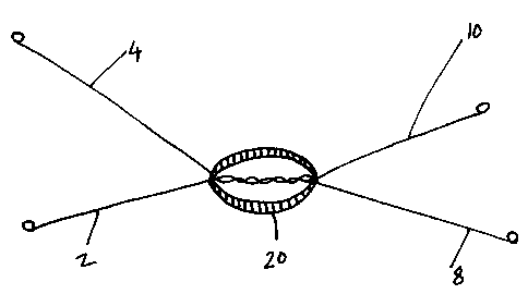
An assembly for use in the cathodic protection of steel reinforcement in
reinforced concrete said assembly comprises: (i) an anode
of a metal having a more negative electrode potential than steel and, in
electrical contact therewith, (ii) an elongate electrical connector eg
a wire made of a ductile metal capable of being wound around the steel
reinforcing element to be protected. The anode may be in the
form of a block cast around a portion of the length of the elongate connector
and preferably the elongate connector comprises a plurality
of wires twisted together over a portion of their length with the anode cast
around the twisted portion.
L'invention concerne un ensemble, utile dans la protection cathodique d'une armature en acier de béton et comprenant : (i) une anode en métal laquelle possède un potentiel d'électrode négatif supérieur à celui de l'acier et est placée en contact avec l'acier, (ii) un connecteur électrique de forme allongée, par exemple un fil métallique en métal ductile, pouvant être enroulé autour de l'élément d'armature en acier à protéger. L'anode peut être sous la forme d'un bloc coulé autour d'une portion de la longueur du connecteur, lequel comprend, de préférence, plusieurs fils métalliques torsadés ensemble sur une portion de leur longueur, l'anode étant coulée autour de cette portion torsadée.
Note: Claims are shown in the official language in which they were submitted.
Note: Descriptions are shown in the official language in which they were submitted.
2024-08-01:As part of the Next Generation Patents (NGP) transition, the Canadian Patents Database (CPD) now contains a more detailed Event History, which replicates the Event Log of our new back-office solution.
Please note that "Inactive:" events refers to events no longer in use in our new back-office solution.
For a clearer understanding of the status of the application/patent presented on this page, the site Disclaimer , as well as the definitions for Patent , Event History , Maintenance Fee and Payment History should be consulted.
| Description | Date |
|---|---|
| Common Representative Appointed | 2019-10-30 |
| Common Representative Appointed | 2019-10-30 |
| Time Limit for Reversal Expired | 2019-10-28 |
| Letter Sent | 2018-10-29 |
| Inactive: Agents merged | 2012-03-06 |
| Appointment of Agent Requirements Determined Compliant | 2009-07-09 |
| Inactive: Office letter | 2009-07-09 |
| Inactive: Office letter | 2009-07-09 |
| Revocation of Agent Requirements Determined Compliant | 2009-07-09 |
| Letter Sent | 2009-06-25 |
| Appointment of Agent Request | 2009-05-15 |
| Revocation of Agent Request | 2009-05-15 |
| Inactive: Single transfer | 2009-05-15 |
| Grant by Issuance | 2007-01-09 |
| Inactive: Cover page published | 2007-01-08 |
| Pre-grant | 2006-10-10 |
| Inactive: Final fee received | 2006-10-10 |
| Notice of Allowance is Issued | 2006-08-17 |
| Notice of Allowance is Issued | 2006-08-17 |
| Letter Sent | 2006-08-17 |
| Inactive: First IPC assigned | 2006-08-06 |
| Inactive: Approved for allowance (AFA) | 2006-07-27 |
| Amendment Received - Voluntary Amendment | 2006-06-07 |
| Inactive: IPC from MCD | 2006-03-12 |
| Inactive: S.30(2) Rules - Examiner requisition | 2005-12-07 |
| Inactive: S.29 Rules - Examiner requisition | 2005-12-07 |
| Letter Sent | 2003-12-04 |
| All Requirements for Examination Determined Compliant | 2003-11-20 |
| Request for Examination Requirements Determined Compliant | 2003-11-20 |
| Request for Examination Received | 2003-11-20 |
| Letter Sent | 2001-01-09 |
| Inactive: Single transfer | 2000-12-06 |
| Inactive: Cover page published | 2000-10-12 |
| Inactive: First IPC assigned | 2000-10-05 |
| Inactive: Courtesy letter - Evidence | 2000-09-26 |
| Inactive: Notice - National entry - No RFE | 2000-09-21 |
| Application Received - PCT | 2000-09-18 |
| Application Published (Open to Public Inspection) | 2000-05-11 |
There is no abandonment history.
The last payment was received on 2006-09-18
Note : If the full payment has not been received on or before the date indicated, a further fee may be required which may be one of the following
Please refer to the CIPO Patent Fees web page to see all current fee amounts.
Note: Records showing the ownership history in alphabetical order.
| Current Owners on Record |
|---|
| VECTOR CORROSION TECHNOLOGIES LTD |
| Past Owners on Record |
|---|
| CHRISTOPHER GORRILL |
| NIGEL DAVISON |

