Sélection de la langue

Search

Sommaire du brevet 2316983 

Énoncé de désistement de responsabilité concernant l'information provenant de tiers

Une partie des informations de ce site Web a été fournie par des sources externes. Le gouvernement du Canada n'assume aucune responsabilité concernant la précision, l'actualité ou la fiabilité des informations fournies par les sources externes. Les utilisateurs qui désirent employer cette information devraient consulter directement la source des informations. Le contenu fourni par les sources externes n'est pas assujetti aux exigences sur les langues officielles, la protection des renseignements personnels et l'accessibilité.

Disponibilité de l'Abrégé et des Revendications

L'apparition de différences dans le texte et l'image des Revendications et de l'Abrégé dépend du moment auquel le document est publié. Les textes des Revendications et de l'Abrégé sont affichés :

  • lorsque la demande peut être examinée par le public;
  • lorsque le brevet est émis (délivrance).
(12) Brevet: (11) CA 2316983
(54) Titre français: CONNECTEUR UTILE DANS LA PROTECTION CATHODIQUE ET PROCEDE D'UTILISATION ASSOCIE
(54) Titre anglais: CONNECTOR FOR USE IN CATHODIC PROTECTION AND METHOD OF USE
Statut: Périmé et au-delà du délai pour l’annulation
Données bibliographiques
(51) Classification internationale des brevets (CIB):
  • C23F 13/16 (2006.01)
  • C23F 13/20 (2006.01)
(72) Inventeurs :
  • DAVISON, NIGEL (Royaume-Uni)
  • GORRILL, CHRISTOPHER (Royaume-Uni)
(73) Titulaires :
  • VECTOR CORROSION TECHNOLOGIES LTD
(71) Demandeurs :
  • VECTOR CORROSION TECHNOLOGIES LTD (Canada)
(74) Agent: ADE & COMPANY INC.
(74) Co-agent:
(45) Délivré: 2007-01-09
(86) Date de dépôt PCT: 1999-10-28
(87) Mise à la disponibilité du public: 2000-05-11
Requête d'examen: 2003-11-20
Licence disponible: S.O.
Cédé au domaine public: S.O.
(25) Langue des documents déposés: Anglais

Traité de coopération en matière de brevets (PCT): Oui
(86) Numéro de la demande PCT: PCT/GB1999/003517
(87) Numéro de publication internationale PCT: WO 2000026439
(85) Entrée nationale: 2000-06-28

(30) Données de priorité de la demande:
Numéro de la demande Pays / territoire Date
09/306,419 (Etats-Unis d'Amérique) 1999-05-06
9823654.0 (Royaume-Uni) 1998-10-29

Abrégés

Abrégé français

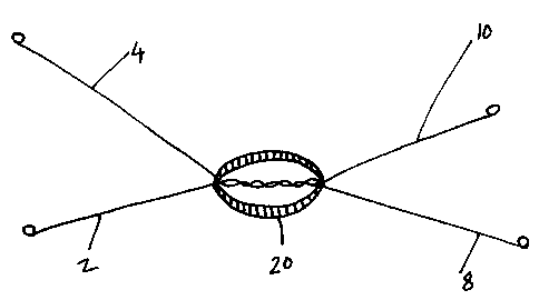
L'invention concerne un ensemble, utile dans la protection cathodique d'une armature en acier de béton et comprenant : (i) une anode en métal laquelle possède un potentiel d'électrode négatif supérieur à celui de l'acier et est placée en contact avec l'acier, (ii) un connecteur électrique de forme allongée, par exemple un fil métallique en métal ductile, pouvant être enroulé autour de l'élément d'armature en acier à protéger. L'anode peut être sous la forme d'un bloc coulé autour d'une portion de la longueur du connecteur, lequel comprend, de préférence, plusieurs fils métalliques torsadés ensemble sur une portion de leur longueur, l'anode étant coulée autour de cette portion torsadée.


Abrégé anglais


An assembly for use in the cathodic protection of steel reinforcement in
reinforced concrete said assembly comprises: (i) an anode
of a metal having a more negative electrode potential than steel and, in
electrical contact therewith, (ii) an elongate electrical connector eg
a wire made of a ductile metal capable of being wound around the steel
reinforcing element to be protected. The anode may be in the
form of a block cast around a portion of the length of the elongate connector
and preferably the elongate connector comprises a plurality
of wires twisted together over a portion of their length with the anode cast
around the twisted portion.

Revendications

Note : Les revendications sont présentées dans la langue officielle dans laquelle elles ont été soumises.


-7
What is claimed is:
1. An assembly for use in the cathodic protection of steel reinforcement in
reinforced concrete said assembly comprising:
(i) an anode of a metal having a more negative electrode potential than steel;
and
(ii) an elongated electrical connector physically and electrically connected
to
said anode and made of a ductile metal; and
wherein said anode is in the form of a block formed around a portion of the
length of
said elongated connector.
2. An assembly as claimed in claim 1 wherein said elongated connector is in
the
form of at least one wire.
3. An assembly as claimed in claim 1 wherein said elongated connector
comprises a plurality of wires twisted together over a portion of their
length, and
wherein said anode has been formed around said twisted portion.
4. An assembly as claimed in claim 3 wherein said wires are twisted together
at
a position intermediate their ends so that said wires extend outwardly from
more than
one side of said anode.
5. An assembly as claimed in claim 1 wherein said anode is enclosed in a
porous material which has been cast around said anode, said porous material
containing an electrolyte solution whose pH is sufficiently high for corrosion
of said
anode to occur and passive film formation on said anode to be avoided when the
anode is galvanically connected to a concrete steel reinforcement.
6. An assembly as claimed in claim 5 wherein said anode is made of zinc and
said porous material is a cementitious mortar containing an electrolyte
solution of pH
at least about 14.

-8
7. An assembly as claimed in claim 1 in combination with a concrete steel
reinforcing element; and wherein said assembly is connected to said
reinforcing
element by winding said elongated connector around said reinforcing element.
8. An assembly as claimed in claim 7 wherein said elongated connector
comprises at least one wire of a material as noble or more noble than the
steel of
said steel reinforcing element.
9. An assembly as recited in claim 8 wherein said elongated connector
comprises a plurality of wires twisted together over a portion of their
length, and
wherein said anode has been formed around said twisted portion.
10. An assembly as claimed in claim 9 wherein said wires are twisted together
at
a position intermediate their ends so that said wires extend outwardly from
more than
one side of said anode.
11. An assembly for use in the cathodic protection of concrete-reinforcing
steel
reinforcing elements, said assembly comprising:
at least first and second wires twisted together at a position intermediate
their ends to
form a twisted portion;
a block of anode material cast around said twisted portion, so that at least
four wire
arms extend outwardly from said block; and
wherein said wires are of ductile metal.
12. An assembly as recited in claim 11 wherein said anode is made of zinc, and
wherein said wires are mild steel, and wherein said anode is enclosed in a
porous
cementitious mortar containing an electrolyte solution of a pH at least about
14.
13. A method of making an assembly for use in the cathodic protection of steel
reinforcement in reinforced concrete using an anode of a metal having a more
negative electrode potential than steel, and an elongated electrical connector
made
of a ductile metal, said method comprising:

-9
(a) melting the metal for the anode, so that it is in liquid form;
(b) placing a part of the length of the connector in a mold; and
(c) casting the anode from the liquid metal in the mold to form a block of
metal
around a portion of the length of the elongated electrical connector.
14. A method as claimed in claim 13 further comprising (d) producing a liquid
or
semi-liquid mixture of a porous material containing an electrolyte solution
having a
pH sufficiently high for corrosion of the anode to occur and passive film
formation on
the anode to be avoided when connected to a steel reinforcement; and (e)
forming a
solid block of the mixture around the anode from (c).
15. A method of installing a sacrificial anode to protect the steel
reinforcement of
reinforced concrete which method comprises in any order:
(a) making an electrical connection between the sacrificial anode and an
elongated connector made of a ductile metal;
(b) making electrical contact between the elongated connector and the steel
reinforcement by winding the elongated connector around the steel
reinforcement;
and after (b)
(c) tightening the electrical connector around the reinforcement by twisting
the
ends of the elongated connector together using a twisting tool.
16. A method as claimed in claim 15 wherein (a) is practiced by casting the
anode from a liquid metal in a mold containing part of the connector to form a
block
of metal around a portion of the length of the elongated connector.
17. A method as claimed in claim 16 further comprising, carried out before or
after (b), (c) casting around the anode a porous material containing an
electrolyte
solution having a pH sufficiently high for corrosion of the anode to occur and
passive
film formation to be avoided.

-10
18. A method as claimed in claim 17 wherein (a)-(c) are practiced using a zinc
anode and using an electrolyte solution having a pH of at least about 14.


Description

Note : Les descriptions sont présentées dans la langue officielle dans laquelle elles ont été soumises.


CA 02316983 2000-06-28
wo oon~9 rc~rics~ro3sm
CONNECTOR FOR USE IN CATHODIC
PROTECTION AND METHOD OF USE.
Field of the Invention
s This invention relates to the cathodic protection of steel in reinforced
concrete
employing a sacrificial anode, more particularly to an electrical connector
for
connecting the sacr~cial anode to the reinforcing steel it is intended to
protect and
to a method for the installation of the anode.
to Background of the Invention
Sacrificial anodes are well known. To be effective the sacrificial anode is
made of
a metal which has a more negative electrode potential than the steel to be
protected so that it will corrode in preference to the steel. Sacrificial
anodes are
described in European Patent No 0707667 and United States Patent No 5292411.
is
Problem to be solved by the Invention
To fulfil its purpose the sacrificial anode needs to be connected electrically
to the
steel to be protected. Metal conductors have been previously used for this
purpose. Previously these metal conductors such as wires, have been attached
to
2o the steel reinforcement by drilling a hole into which a self tapping screw
is
inserted. Alternative methods have involved the use of clips or clamps to
secure
the wire to the metal to be protected.
These methods have problems in that the drifting of holes and use of self
tapping
2s screws is time consuming and there is always a risk that the clips and
clamps may
be dislodged.
The present invention provides a solution to these problems by the use of a
ductile elongate connector that is connected to the steel reinforcing element
by
3o winding the connector around the reinforcing element..

CA 02316983 2000-06-28
wo oons~9 rcrics~ro3s~ ~
-2-
Summary of the Invention
According to the present invention there is provided an assembly for use in
the
catholic protection of steel reinforcement in reinforced concrete said
assembly
comprising:
s (i) an anode of a metal having a more negative electrode potential than
steel and,
in electrical contact therewith,
(ii) an elongate electrical connector made of a ductile metal capable of being
wound around the steel reinforcing element to be protected.
to Advantageous Effect of the Invention
The connector can be installed in less time than the previously used methods
involving the use of self tapping screws and is more secure than the clips or
clamps:
~s Brief Description of the Drawings
Fig 1 is a perspective view of one embodiment of the invention in which two
wires
are twisted together
Fig 2 is a perspective view on a smaller scale than Fig 1 in which the anode
has
been cast around the wires of the connector and
20~ Fig 3 is a perspective view on the same scale as Fig 2 of another
embodiment in
which the anode is surrounded by a mortar which been cast around it.
Detail~d Description of the Invention.
The anode is preferably zinc but aluminium, cadmium or magnesium may be
2s used. References to these metals include alloys containing them.
The electrical contact between the connector and the anode is preferably
provided
by having the anode in the form of a block which has been cast (by cast we
mean
allowing the liquid metal to solidify to form the block) around a portion of
the length
30 of the elongate connector. Alternatively the electrical contact may
provided by the
elongate connector being wound around the anode or by the connector being
soldered or similarly attached to the anode.
The elongate connector is conveniently in the form of a wire, although other
elongate forms may be used. The wire may conveniently be of steel, preferably
a
3s mild steel.
Preferably the wire is as noble or more noble than the steel of the
reinforcement.

CA 02316983 2000-06-28
wo oon~9 rcricB~ro3si ~
-3-
The connector may comprise a plurality of wires twisted together over a
portion of
their length and the anode may be cast around the twisted portion. By the word
twisted we mean to include folded or bent or crimped. The purpose of the
twisted
portion is to increase the surface area of the wire forming the interface with
the
s cast anode and thereby improve the electrical contact. The wires may be
twisted
together at a position which is intermediate their ends (for example near the
middle of their lengths) so that lengths of wire extend on both sides of the
cast
anode.
io Patent Application No WO 94/29496 (European Patent Application No 0707667)
describes a method of cathodic protection in which to maintain the cathodic
protection over a sustained period of time the anode is surrounded by a
material
containing an electrolyte of high pH. To avoid passivation of the anode it
recommends that in the case of a zinc anode the pH is at least about 14.
~s
Suitable materials described in this patent are cementitious mortars which may
be
cast around the anode to form a unit. It is not essential that the mortar is
cementitious although such mortars are more readily available. The mortar may
be prepared from a cement that has an intrinsically high alkali content or
additions!
2o alkali may be added to the mortar eg sodium hydroxide or lithium hydroxide,
the
latter being preferred.
The assembly of anode and - connector of the present invention may have a
porous material eg a cementitious mortar cast around the anode. By cast we
2s mean forming a solid block from the liquid or semiliquid mortar. The
casting is
preferably carried out in a mold. The porous material is one that preferably
contains a high pH electrolyte as described in European Patent Application No
0707667 ie one containing an electrolyte solution whose pH is sufficiently
high to
maintain corrosion of the anode and passive film formation on the anode to be
3o avoided when the anode is galvanically connected to the steel
reinforcement. In
the case of a cementitious mortar the electrolyte solution is the pore
solution.
The mortar will preferably.have a content of alkali equivalent to at least 1 %
lithium
hydroxide based on the dry weight of the ingredients used to make the mortar.
An
3s equivalent amount of sodium hydroxide is 2% by weight. Conveniently the
amount
of lithium hydroxide is greater than 2% or an equivalent amount of sodium
hydroxide of 4%.

CA 02316983 2000-06-28
wo eons~9 rcrics~ro3sm
Lithium hydroxide is the preferred alkali because lithium ions provide
protection
against alkali silica (or alkali aggregate) reactions in concrete. However
mixtures
of alkalis may be used for example mixtures of lithium hydroxide and sodium
hydroxide.
s
The anode, the porous material eg mortar and the casting may also be as
described in European Patent Application No 0707667.
~o
According to another aspect of the present invention there is provided a
method of
installing a sacrificial anode to protect the reinforcement of reinforced
concrete
which method comprises the following steps (a) and (b) in any order
(a) making an electrical connection between an elongate connector and the
anode
i s and
(b) making electrical contact with the steel reinforcement by winding the
elongate
connector around the steel reinforcement.
The step (a) may comprise casting the anode around a portion of the length of
the
2o elongate connector.
A further step (c) may be carried out before or after step (b) which step (c)
comprises casting around the anode a porous material containing an electrolyte
solution having a pH suffcciently high for corrosion of the anode to occur and
2s passive film formation to be avoided.
Preferably the anode is zinc in which case the pH of the electrolyte solution
is
desirably at least about 14. When the anode is of another metal such as
aluminium the pH may be lower, for example at least 13.3 or 13.5
3o The pH may be determined by measuring the hydroxyl ion concentration and
applying the equation
pH = 14 + log (OH-) after Sorensen.
The invention is applicable to the construction of new reinforced concrete
3s structures in which the anode assembly is connected to the reinforcement by
means of the connector and a high pH porous material such as a mortar cast
around the anode.

CA 02316983 2006-06-07
-5-
The invention is also applicable to the protection of existing concrete
structures in
which method a hole may be made in the concrete and (l) the anode inserted
into
the hole and (ii) the connector connected to the reinforcement and (iii) the
high
pH material cast around the anode. Steps (l), (ii) and (iii) may be carried
out in any
3 order
Referring to 1=ig 1 of the drawings two wires each being a 18 8WG (standard
wire
guage) mild steel wire are twisted together over part of their length at 6_
The
length Of the twisted portion 6 is typically from about 38 to 42 mm. Four
lengths of
vo uvire in the form of arms 2, 4. 8 and 'I0 extend from the twisted portion
6. The
length of the arcns 2, 4. 8 and I o is typically from about 148 to 152mm and
at the
end of each arm are loops 12, 13 'i4 and 5. The arms are each wound around
the reinforaetllent. Usually one or two complete winds around the
reinforcement is
sufficient to make a satisfactory electrical contact. The diameter of the
Poops is
l s typically from about 9 to 1 t mm. The purpose of the loops is to
facilitate the use of
a toot of the type used to close paper sacks for potatoes and the tike. A
suitable
too! iS a spring loaded watchet twisting tool known as the Stanley tying tool
and is
available from Direct Wtre Ties Limited. 8y means of the toot the arms which
have
been wound around the steel reinforcement (not shown) in reinforced concrete
2o may then be twisted together. This has the effect of tightening the wire
around the
reinforcement.
In Fig z a cylindrical zinc block 2t) of about 40 mm diameter and about 7mm
thleKness has been cast around the twisted wires. tn the Figure the centre of
the
~s cylindrical biook 20 has been omitted to show the wires. The top and bottom
edges of the btOdc 20 have been rounded to prevent crack inducement.
The assembly shown in Fig 2 was made by first twisting the wires together neat
the middle of their length and placing the twisted portion in a ceramic
casting
30 mould. Molten zinc was then poured into the mould. After solidifying the
product
which was recroved from the mould. The wire arms 2, 4 8, and 1U extend on both
sides of the anode and enable the anode to be connected to more than one
reinforcing element if desired.
as !n Fig 3 a block of mortar 2~ has been cast around the zinc shown in Fig 2
to give
a thickness of 10 mm all round the zinc.

CA 02316983 2000-06-28
wo oor~r~9 Pc~ricB~ro3sm
The assembly shown in Fig 3 was made by positioning the assembly shown in Fig
2 in a previously vacuum formed plastic mould so as to locate the zinc
centrally in
the mould. A high pH cementitious mortar containing a pore solution of pH
greater
than 14 was prepared by mixing a Portland cement powder (containing 2% by
s weight of added lithium hydroxide based on the weight of the cement powder)
with
water and poured into the mould. This was allowed to harden for four hours and
then removed from the mould to yield the product shown in Fig 3.

Dessin représentatif
Une figure unique qui représente un dessin illustrant l'invention.
États administratifs

2024-08-01 : Dans le cadre de la transition vers les Brevets de nouvelle génération (BNG), la base de données sur les brevets canadiens (BDBC) contient désormais un Historique d'événement plus détaillé, qui reproduit le Journal des événements de notre nouvelle solution interne.

Veuillez noter que les événements débutant par « Inactive : » se réfèrent à des événements qui ne sont plus utilisés dans notre nouvelle solution interne.

Pour une meilleure compréhension de l'état de la demande ou brevet qui figure sur cette page, la rubrique Mise en garde , et les descriptions de Brevet , Historique d'événement , Taxes périodiques et Historique des paiements devraient être consultées.

Historique d'événement

Description Date
Représentant commun nommé 2019-10-30
Le délai pour l'annulation est expiré 2019-10-28
Lettre envoyée 2018-10-29
Inactive : Regroupement d'agents 2012-03-06
Exigences relatives à la nomination d'un agent - jugée conforme 2009-07-09
Inactive : Lettre officielle 2009-07-09
Exigences relatives à la révocation de la nomination d'un agent - jugée conforme 2009-07-09
Lettre envoyée 2009-06-25
Demande visant la nomination d'un agent 2009-05-15
Demande visant la révocation de la nomination d'un agent 2009-05-15
Inactive : Transfert individuel 2009-05-15
Accordé par délivrance 2007-01-09
Inactive : Page couverture publiée 2007-01-08
Préoctroi 2006-10-10
Inactive : Taxe finale reçue 2006-10-10
Un avis d'acceptation est envoyé 2006-08-17
Lettre envoyée 2006-08-17
Inactive : CIB en 1re position 2006-08-06
Inactive : Approuvée aux fins d'acceptation (AFA) 2006-07-27
Modification reçue - modification volontaire 2006-06-07
Inactive : CIB de MCD 2006-03-12
Inactive : Dem. de l'examinateur par.30(2) Règles 2005-12-07
Inactive : Dem. de l'examinateur art.29 Règles 2005-12-07
Lettre envoyée 2003-12-04
Toutes les exigences pour l'examen - jugée conforme 2003-11-20
Exigences pour une requête d'examen - jugée conforme 2003-11-20
Requête d'examen reçue 2003-11-20
Lettre envoyée 2001-01-09
Inactive : Transfert individuel 2000-12-06
Inactive : Page couverture publiée 2000-10-12
Inactive : CIB en 1re position 2000-10-05
Inactive : Lettre de courtoisie - Preuve 2000-09-26
Inactive : Notice - Entrée phase nat. - Pas de RE 2000-09-21
Demande reçue - PCT 2000-09-18
Demande publiée (accessible au public) 2000-05-11

Historique d'abandonnement

Il n'y a pas d'historique d'abandonnement

Taxes périodiques

Le dernier paiement a été reçu le 2006-09-18

Avis : Si le paiement en totalité n'a pas été reçu au plus tard à la date indiquée, une taxe supplémentaire peut être imposée, soit une des taxes suivantes :

  • taxe de rétablissement ;
  • taxe pour paiement en souffrance ; ou
  • taxe additionnelle pour le renversement d'une péremption réputée.

Veuillez vous référer à la page web des taxes sur les brevets de l'OPIC pour voir tous les montants actuels des taxes.

Titulaires au dossier

Les titulaires actuels et antérieures au dossier sont affichés en ordre alphabétique.

Titulaires actuels au dossier
VECTOR CORROSION TECHNOLOGIES LTD
Titulaires antérieures au dossier
CHRISTOPHER GORRILL
NIGEL DAVISON
Les propriétaires antérieurs qui ne figurent pas dans la liste des « Propriétaires au dossier » apparaîtront dans d'autres documents au dossier.
Documents

Pour visionner les fichiers sélectionnés, entrer le code reCAPTCHA :


Pour visualiser une image, cliquer sur un lien dans la colonne description du document. Pour télécharger l'image (les images), cliquer l'une ou plusieurs cases à cocher dans la première colonne et ensuite cliquer sur le bouton "Télécharger sélection en format PDF (archive Zip)" ou le bouton "Télécharger sélection (en un fichier PDF fusionné)".

Liste des documents de brevet publiés et non publiés sur la BDBC .

Si vous avez des difficultés à accéder au contenu, veuillez communiquer avec le Centre de services à la clientèle au 1-866-997-1936, ou envoyer un courriel au Centre de service à la clientèle de l'OPIC.


Description du
Document 
Date
(aaaa-mm-jj) 
Nombre de pages   Taille de l'image (Ko) 
Abrégé 2000-06-28 1 55
Description 2000-06-28 6 282
Revendications 2000-06-28 3 109
Dessins 2000-06-28 2 20
Page couverture 2000-10-12 1 41
Dessin représentatif 2005-11-21 1 5
Description 2006-06-07 6 280
Revendications 2006-06-07 4 120
Page couverture 2006-12-29 1 39
Avis d'entree dans la phase nationale 2000-09-21 1 193
Courtoisie - Certificat d'enregistrement (document(s) connexe(s)) 2001-01-09 1 113
Rappel de taxe de maintien due 2001-07-03 1 112
Accusé de réception de la requête d'examen 2003-12-04 1 188
Avis du commissaire - Demande jugée acceptable 2006-08-17 1 162
Courtoisie - Certificat d'enregistrement (document(s) connexe(s)) 2009-06-25 1 102
Avis concernant la taxe de maintien 2018-12-10 1 184
Avis concernant la taxe de maintien 2018-12-10 1 183
Correspondance 2000-09-21 1 15
PCT 2000-06-28 1 38
Taxes 2003-09-17 1 20
Taxes 2002-10-01 1 68
Correspondance 2006-10-10 2 45
Correspondance 2009-05-15 2 72
Correspondance 2009-07-09 1 13
Correspondance 2009-07-09 1 16