Note: Descriptions are shown in the official language in which they were submitted.
CA 02317122 2000-06-30
WO OOI25692 PCT/US99I25Z60
METHOD AND APPARATUS FOR REMOVING TISSUE
FROM A REGION OF INTEREST
USING STEREOTACTIC RADIOGRAPHIC GUIDANCE
BACKGROUND OF THE INVENTION
Field of the Invention
The present invention generally relates to a method and apparatus for the
removal of tissue from a region of interest in a body part of a patient. More
particularly, the present invention relates to a method and apparatus for the
removal of tissue from a region of interest in a body part of a patient, such
as a
breast, wherein the tissue removal is guided by stereotactic radiography.
Description of the Prior Art
Stereotactic mammographic devices have been used to determine the three
dimensional coordinates of a region of interest in a breast relative to a
point of
reference on the stereotactic devices. The three dimensional coordinates are
generally used for diagnostic and surgical procedures, and more particularly
to
insert the end of a wire, the tip of a biopsy needle or the tip of a rotary
cutting
tool into the region of interest in the breast. Wires are generally used to
guide a
surgeon to the region of interest to remove part or all thereof. The biopsy
needle
is typically used to sample cells or tissue from the region of interest. The
rotary
cutting tool is generally used for the removal of tissue from the region of
interest.
One example of a stereotactic mammographic device is described in U.S.
Patent No. 5,289,520, which is incorporated by reference in its entirety. The
commercial embodiment of the device described and illustrated in the patent
has
been used to guide a biopsy needle into a region of interest to obtain samples
of
cells and tissue. Also, such device has been used to guide rotary surgical
cutting
instruments to remove tissue from a region of interest.
As described in C.W. Putnam, "Techniques of Ultrasonic Dissection in
Resection of the Liver", Surgery. Gynecolo~v & Obstetrics, Vol. 157, pgs. 474-
478, November, 1983, ultrasonic aspirated dissectors, such as the Cavitron
CA 02317122 2000-06-30
WO 00/25692 PCT/US99/25260
Ultrasonic Surgical Aspirator, comprise a handpiece which is connected to a
control console. The handpiece contains a water-cooled magnetostrictive
transducer that activates a hollow titanium tip along its longitudinal axis at
a
frequency of approximately 23,000 cycles per second. The tip of the handpiece
is
irrigated and a suction line is connected to the hollow tip to aspirate the
irrigant,
blood and tissue fragments. The instrument works by generating ultrasonic
vibrations which selectively fracture tissue in proportion to its water
content. The
fractured tissue is removed via the suction line.
Typically such ultrasonic surgical aspirators are controlled by hand in an
open surgical procedure which is not minimally invasive. However, as the above
referenced article suggests, such devices are used because they afford greater
differentiation between the various types of tissue structure found during a
surgical
procedure involving a liver, for example. Heretofore, it is not believed that
an
ultrasonic surgical aspirator has generally been used as a minimally invasive
tool
to remove tissue from a region of interest in a patient's body part, such as a
breast, nor has such a tool been guided by a stereotactic radiographic device
to
remove tissue from the region of interest.
SUMMARY OF THE INVENTION
Accordingly, it is a principal object of the present invention to guide an
ultrasonic surgical aspirating tissue removal tool to a region of interest
inside a
patient's body part.
It is another object of the present invention to guide and control a tissue
removal tool within a volume surrounding a region of interest inside a
patient's
body part.
These objects are accomplished, at least in part, by providing a method and
apparatus for removing tissue from a volume surrounding a region of interest
within the body part of a patient. The apparatus comprises a body part holder
adapted to hold the body part immobile. It also defines a predetermined point
of
reference relative to the immobile body part. The apparatus employs a
stereotactic
imaging assembly having an radiation transmission source adapted to receive
2
CA 02317122 2000-06-30
wo oor~s6n rcrius99ns26o
operating instruction signals and to irradiate the body part, and a radiation
receiver
adapted to transmit image signals corresponding to radiation received from the
transmission source passing through the body part to obtain stereotactic
images of
the held body part and the region of interest therein. The apparatus includes
a
display adapted to receive display signals and to display stereotactic images
of the
body part and region of interest therein corresponding to the display signals
received. A user interface, adapted to interactively enable a user to place a
boundary around the region of interest 'of the body part displayed, provides
boundary signals representing the dimensions and location thereof around the
region of interest. The apparatus also includes a motorized tissue removal
tool
guiding stage capable of moving relative to the predetermined point of
reference.
The removal tool guiding stage is adapted to receive drive signals to drive
the
stage to a position relative to the predetermined point of reference and is
further
adapted to provide position indicating signals to indicate the position of the
stage
relative to the predetermined point of reference. A tissue removal tool is
held by
the tool guiding stage. The tissue removal tool has a fragmenting tip and a
means
for extracting or removing fragmented tissue from the fragmenting tip. The
apparatus is directed by a controller adapted to: provide operating signals to
the
radiation source to cause the radiation source to transmit radiation; receive
image
signals from the radiation receiver; provide display signals to the display
based
upon the image signals received; receive boundary signals from the user
interface;
provide boundary display signals to the display based upon the boundary
signals
received; calculate the size and location of a tissue removal volume relative
to the
predetermined point of reference based upon the boundary signals received;
provide drive signals to the motorized guiding stage to command the stage to
move
to a position within the calculated tissue removal volume; and receive
position
indicating signals from the guiding stage.
The method of the present invention comprises several steps including:
holding a body part of a patient having a region of interest therein relative
to a
predetermined point of reference; obtaining stereotactic images of the body
part
containing the region of interest therein; and displaying the stereotactic
images.
3
CA 02317122 2000-06-30
wo oons6~ PcT~s~ns26o
Once the stereotactic images are displayed, the method involves the following
additional steps: placing a boundary around the region of interest in each
displayed
stereotactic image; determining the size and location of a tissue removal
volume
surrounding the region of interest relative to the predetermined point of
reference
from the location, dimensions and relative geometry of the boundaries; holding
a
tip of a tissue removal tool relative to the predetermined paint of reference;
and
moving the tip of the tissue removal tool within the tissue removal volume to
remove tissue from within the tissue removal volume.
Other objects and advantages of the present invention will become apparent
to those skilled in the art from the following detailed description read in
conjunction with the attached drawings and claims appended hereto.
BRIEF DESCRIPTION OF THE DRAWINGS
The drawings, not drawn to scale, include:
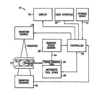
FIG. 1 is a schematic diagram of the apparatus for removing tissue and for
monitoring the tissue removal method
Fig. 2 is a side view of a stereotactic mammography needle biopsy
apparatus for guiding and controlling an ultrasonic surgical aspirating tissue
removal tool according to the method of the present invention;
FIG. 3 is a perspective view of an ultrasonic aspiration device;
FIGS. 4A, 4B and 4C are side, front and overhead schematic views of the
aspirator and stage;
FIGS. SA and SB are schematic illustrations of the aspirator and stage
pivoting about a pivot point;
FIG. 6 is a flow diagram of the method of the present invention;
FIGS. 7A and 7B are plan views of left and right stereotactic images of a
breast containing a region of interest;
FIG. 8 is a combined perspective view of the geometrical relationship of
the boundaries drawn around the region of interest displayed in the
stereotactic
images;
4
CA 02317122 2000-06-30
WO 00125692 PCT/US99/25260
FIG. 9 is a plan view of the geometrical relationship of the boundaries
drawn around the region of interest further illustrating the derivation of the
tissue
removal volume; and
FIG. 10 is a three dimensional plot of the sensor indications versus the
removal tool position in terms of Cartesian coordinates.
DETAILED DESCRIPTION OF THE INVENTION
The present invention relates to 'a method and apparatus for removing tissue
from a volume surrounding a region of interest in a body part. While the
present
invention will be discussed in the context of a suspicious lesion contained
within a
breast which has been previously diagnosed by mammographic biopsy procedures,
those skilled in the art will appreciate that the present invention may be
used on
other body parts containing regions of interest in which tissue is to be
removed.
The apparatus of the present invention will be discussed first followed by a
discussion of the method.
The Apparatus
Referring to FIG. 1, the apparatus for removing tissue from a volume
surrounding a region of interest within the body part of a patient is
comprised of
several components. The apparatus 10 includes a body part holder 12 adapted to
hold a body part 14, such as a breast, immobile and to define a predetermined
point of reference. It also includes a stereotactic imaging assembly having a
radiation transmission source 16 adapted to receive operating instruction
signals
and to irradiate the body part 14, and a radiation receiver 18 adapted to
transmit
image signals corresponding to radiation received from the transmission source
16
passing through the body part 14. The imaging assembly is further adapted to
obtain stereotactic images of the body part 14 held by holder 12 and the
region of
interest therein.
The apparatus also includes a display 24 which adapted to receive display
signals and to display stereotactic images of the body part 14 and region of
interest
therein corresponding to the display signals received. The display 24 may be
an
S
CA 02317122 2000-06-30
WO 00/25692 PCT/US99I25260
ordinary video display having suitable contrast and spatial resolution
capacity to
permit visualization of the region of interest within the body part.
The apparatus is further provided with a user interface 26 that is adapted to
enable a user to interactively provide a visible boundary around the region of
interest in the body part 14 displayed in each stereotactic image. Such an
interface
may be a keyboard, mouse, joystick or trackball, for example, which interfaces
with controlling software. The interface also enables a boundary signal
representing the dimensions and position of the visible boundary to be formed
for
each boundary which is used for calculating a tissue removal volume as
described
below.
The apparatus further includes a motorized tissue removal tool guiding
stage 28 capable of moving relative to the predetermined point of reference
defined by the holder 12. The removal tool is adapted to receive drive signals
to
drive the stage 28 to one or more positions relative to the predetermined
point of
reference. The stage is also adapted to provide position indicating signals to
indicate the position of the stage relative to the predetermined point of
reference
defined by the holder 12.
A tissue removal tool 30 is held by the tool guiding stage 28. Preferrably,
the tissue removal tool has a fragmenting tip 32 and a conduit 34 for
extracting or
removing fragmented tissue from the fragmenting tip 32.
The above described components of the apparatus are controlled by a
controller 36, which may be formed by any commercially available computer
having sufficient processing speed and memory such as a computer having a
Intel
Pentium II ~''~'' processor operating at 300 Mhz with 64 MBytes of RAM. The
controller 36 is adapted to coordinate a number of functions of the apparatus
including: providing operating signals to the radiation source 16 to cause the
radiation source to transmit radiation; receiving image signals from the
radiation
receiver 18; providing display signals to the display 24 based upon the image
signals received; receiving boundary signals as created by the user interface
26;
providing boundary display signals to the display 24 based upon the boundary
signals received; calculating the size and location of a tissue removal volume
6
CA 02317122 2000-06-30
WO 00/25692 PCT/US99/25260
relative to the predetermined point of reference defined by the holder 12
based
upon the boundary signals received. The controller also provides drive signals
to
the motorized guiding stage 28 to command the stage to move to a position
within
the calculated tissue removal volume, and receives position indicating signals
from
the guiding stage 28.
A more advanced embodiment of the present invention includes a removed
tissue sensor 38 connected to the tissue removal tool's conduit 34. Extracted
tissue is passed through the tissue sensor via the conduit 34. The tissue
sensor 38
is adapted to sense whether removed tissue contains a detectable marking
substance which has been injected into the body part with the intention of
marking
the tissue in the region of interest with the detectable marking substance.
The
removed tissue sensor is further adapted to provide sensing signals to the
controller 36 and it in turn is suitably adapted tv receive such signals from
the
tissue sensor. it is known to use certain radioactive isotopes to mark
cancerous
tissue because such isotopes tend to concentrate around such tissue. Thus,
assuming that the region of interest is comprised of cancerous tissue, the
tissue
removed from the region of interest should cause the sensor 38 to indicate
that the
tissue was in the region of interest due to the high concentration of
radioactive
isotopes being present in the removed tissue. Assuming that the tissue
surrounding
the region of interest is not cancerous and therefore there is no
concentration or a
low concentration of radioactive isotopes, the material removed around the
region
of interest, but outside thereof, will typically not be sensed by the tissue
sensor 38
if the threshold for the sensor is correctly calibrated.
The apparatus may be provided with an optical or magnetic data storage
device 37 that can store the signals generated by the tissue sensor and the
position
indicating signals from the stage 28. The data may be recalled from the
storage
device 37 by the controller to form and display a map of the tissue sensor
signal
versus the position indicating signal.
FIG. 2 illustrates a prone stereotactic mammography apparatus which is
typically used for stereotactic mammographic guided needle biopsies of the
breast
and which may be used with the present invention. A detailed description of
the
7
CA 02317122 2000-06-30
wo oonssn Pcrius99ns26o
prone stereotactic apparatus 10 can be found in U.S. Patent No. 5,289,520,
which
is incorporated herein by reference. The StereoGuiderM stereotactic
mammography apparatus which is commercially available from Trex Medical
Corporation is a device operating under the configurations and principals
described
in U.S. Patent No. 5,289,520.
Generally, the stereotactic apparatus depicted in FIG. 1 has a stereotactic
imaging assembly comprising an X-ray tube 16 and an image receiver 18 mounted
on an imaging arm 42 capable of moving relative to the breast to provide two
stereotactic images. The apparatus has a holder 12 for holding the breast
immobile and compressed. More specifically, the holder 12 comprises a movable
compression paddle 44 and movable compression plate 46 and these define a
predetermined point of reference about the breast 14.
The configuration of the stereotactic apparatus illustrated in FIG. 1 is
preferred in the present invention due to image acquisition advantages
resulting
from the relative configuration of the imaging arm and compression arm. Such
advantageous configuration is described in U.S. Patent No. 5,289,250 and U.S.
Patent No. 5,594,769, which is incorporated herein by reference. However,
other
stereotactic mammography biopsy devices, including both upright and prone
using
other imaging and compression configurations may also be used. An example of
such other configurations may be found in Ericson, U.S. Patent No. 4,727,565,
entitled "Method of Localization. "
The stereotactic apparatus IO illustrated in FIG. I contains a motorized
guiding stage 28 which may be adapted for the purposes of the present
invention.
Typically the stage is used for guiding a biopsy needle instrument or rotary
cutting
tool, held in holder 48 that is suitably adapted for holding such devices.
According to the present invention, the holder 48 may be modified, as
required, to
hold an ultrasonic surgical aspiration tissue removal tool in a manner in
which the
tip of such tool may be guided to a region of interest within a breast
pendulantly
presented in the stereotactic apparatus, as illustrated. In the case of the
ultrasonic
aspirated tool depicted in FIG. 3, as further discussed below, the holder
needs to
be fabricated so that it will not interfere with the tool's operation.
8
CA 02317122 2000-06-30
WO 00125692 PCT/US99/25260
FIG. 3 illustrates a commercially available ultrasonic aspirated tissue
removal tool 50 made by Valleylab, Inc., and marketed under the trademark
CUSA°. The tool comprises a transducer 52 surrounded by an electric
coil 54.
The coil causes the transducer, and the tip 32 thereof, to vibrate at
ultrasonic
frequencies. The tool also includes an irrigation duct 58 for providing
irrigation at
the tip 32 and the aspiration conduit 34 which provides an aspiration source
to
remove tissue fragments located at or near the tip 32. As described above, the
conduit 34 may be connected to the tissue sensor 38. Removed tissue in the
conduit 34 may be passed through the sensor to determine whether the tissue
removed is from the region of interest as such tissue contains a marking
substance
that can be detected by the sensor. While the CUSA° ultrasonic
aspirated tissue
removal tool has been discussed herein, those skilled in the art will
appreciate that
other configurations of ultrasonic aspirated tissue removal tools will also
work for
the proposes of the present invention. Also, those skilled in the art will
also
appreciate that other types of tissue removal tools may also be employed in
the
present invention.
FIGS. 4A, 4B and 4C are side, front and overhead schematic views of the
aspirator and stage illustrating the X, Y and Z directions of the orthogonal
movement of the stage 28 and ultrasonic aspirated tissue removal tool 30.
FIGS. SA and SB illustrate that the stage 28 may be further pivoted, if
desired,
about an arbitrarily selected pivot point 60 of the aspirator.
The Method
The method for removing tissue from a volume surrounding a region of
interest within the body part of a patient comprises several steps which will
be
described further below with general reference to FIG. 6. In the method 100,
the
first step (step 102) is to hold a body part of a patient having a region of
interest
therein. Such holding also establishes a predetermined point of reference for
the
apparatus.
The next step (step 104) in the method is to obtain stereotactic images of
the body part 14 containing the region of interest 15 therein. This step is
9
CA 02317122 2000-06-30
WO 00/25692 PCT/US99/25260
performed in an ordinary manner, for example, as described in U.S. Patent No.
5,289,520. Once the images are obtained, they are displayed (step 106) as
illustrated in FIGS. 7A and 7B together with the point of reference 17.
As further illustrated in FIGS. 6, 7A and 7B, via the user interface, a
boundary 62a, 62b is interactively placed (step 108) around the region of
interest
appearing in each displayed stereotactic image 64a, 64b. Referring to FIGS.
6, 8 and 9, the controller 20 calculates the size and three dimensional
location of a
tissue removal volume 66 surrounding the region of interest 15 relative to the
predetermined point of reference based upon the location, relative geometry
and
10 dimensions of the boundaries 62a, 62b. The three dimensional location of
the
removal volume is calculated in an ordinary manner for calculating the
position of
a region of interest appearing in stereotactic images relative to the point of
reference 17 appearing in the images. A description. of such calculations is
provided in U.S. Patent No. 5,289,520.
15 The dimensions of the removal volume 66 are defined by the letters a, b, c
in FIGS. 8 and 9. As illustrated in FIG. 9, the dimensions a and b are derived
by
drawing a rectangular perimeter around the crossing diagonals formed by the
boundaries 62a, 62b when the perspective view of FIG. 8 is viewed overhead as
in FiG. 9. Dimensions a and b will vary according to the dimensions of the
boundaries 62a, 62b drawn around the region of interest and the angle (alpha)
used for stereotactic imaging. Dimension c is the height of the boundaries,
which
will vary according to the dimensions of the boundaries drawn around the
region
of interest. The method preferably assumes that the dimensions of the
boundaries
62a, 62b placed over the regions of interest in the respective stereotactic
images
64a, 64b are the same. This will have the affect of simplifying and speeding
the
calculations. However, the assumption is not absolutely required for the
purpose
of the present invention. Also, the boundaries 62a, 62b have been illustrated
as
being square. However, those skilled in the art will now appreciate that the
boundaries 62a, 62b need not be square in shape, they could be rectangular,
CA 02317122 2000-06-30
wo oons69z rcTms~nsa6o
circular or elliptical, for example, and the shape of the calculated removal
volume
66 will change accordingly since its dimensions and shape are dictated by the
dimensions and shape of the boundaries 62a, 62b.
As further illustrated in FIG. 6, the next step (step 110) is holding a tip of
a tissue removal tool relative to the predetermined point of reference and
such step
is followed by moving the tip of the tissue removal tool (step 112) within the
tissue removal volume 66 to remove tissue from within the tissue removal
volume.
If desired, the tissue in the region of interest 15 may be marked with a
radioactive
isotope and the removal of such tissue may be monitored (step 114) to develop
a
three dimensional map of the tissue removal process versus coordinates of the
tissue removal tool's tip, which is derived from knowledge of the position of
the
tip relative to the guiding stage and guiding stage position.
An exemplary map 70 from such step is illustrated in FIG. 10. A three
dimensional pattern 72 versus the orthogonal coordinates of the tip of the
tissue
removing tool is depicted. The pattern is comprised of a plurality of points
indicating that the tissue sensor detected marked tissue or did not detect
marked
tissue. The pattern provides an image of the results from the tissue removal
surgical procedure.
It will thus be seen that the objects and advantages set forth above and
those made apparent from the preceding descriptions, are efficiently attained
and,
since certain changes may be made in the above construction without departing
from the scope of the invention, it is intended that the matter contained in
the
above description or shown in the accompanying drawings shall be interpreted
as
illustrative and not in a limiting sense. It is also to be understood that the
following claims are intended to cover all of the generic and specific
features of
the invention herein described, and all statements of the scope of the
invention
which, as a matter of language, might be said to fall therebetween.
11