Note: Descriptions are shown in the official language in which they were submitted.
~ CA 02317279 2007-07-04
"Flooring"
Field of the Invention
The present invention relates to floorings having a
treading layer extending in a given plane and supporting
formations which extend from the treading layer. Some of the
supporting formations extend in a direction that is oblique
with respect to the given plane of the treading layer.
Background of the Invention
Floorings of the type specified above have, over the
years, found extensive use in a very wide range of
applications. A particularly extensive sector of use is that
of floorings for sports and athletics facilities, the two terms
"sports" and "athletics" being here used in their widest
acceptation, i.e., also comprising installations such as
gymnasia or fitness centres or medical centres, surgeries for
carrying out medical examinations on sportsmen, etc.
Figure 1 represents an ideal vertical cross section of a
flooring according to the prior art. In particular, it is the
flooring sold under the trade name SPORTFLEX SUPER X'r" by the
present applicant.
The flooring in question consists of a generally laminar
or sheet-like 1, in which it is possible to distinguish:
- a treading layer 2 designed to face upwards in normal
conditions of laying of the flooring 1; and
- an ensemble of supporting formations 3, in general
presenting a structure that may be defined as pedunculate.
In practice, the flooring 1 is made, for example, starting
from mixtures of isoprene rubber by means of one or more
cascaded calendering operations. In this way it is possible to
provide on the upper face 4 of the treading layer 2 with a
generally corrugated pattern, which is primarily aimed at
providing a non-slip surface. The ensemble of supporting
formations 3 usually takes the form of a reticulated-type
structure comprising one first array made up of a series of
ribs 5 connected together by a second array formed by
respective ribs 6, which are orthogonal to the former
CA 02317279 2000-08-29
2
ones and which basically resemble formations that
extend like bridges connecting adjacent ribs 5.
In the specific solution according to the prior art
illustrated in Figure 1, the height or depth of the
bridges 6 (with respect to the general plane of
extension of the treading surface 2) is slightly
smaller than that of the ribs 5.
The characteristics of a flooring of the type
described above can be identified in a quantitatively
precise way by resorting to the elastic impact test
according to the DIN 18035/6 Standard. This standard,
in agreement with the DIN 18032/2 Standard, makes it
possible to define a parameter, referred to as KA
(abbreviation of the German word Kraftabbau), which
substantially corresponds to a characterization, in
percentage terms, of the behaviour of the flooring
subjected to the fall of a weight of standard
dimensions with respect to the behaviour of a rigid
plane, typically a cement floor, when subjected to the
same impact.
The floorings designed to be used in gymnasia
generally have a KA coefficient of between 15-20% and
30-50%. The lower value of the aforesaid range
corresponds to a flooring that can be characterized as
rather "hard", whereas the upper limit corresponds to a
flooring that proves somewhat "soft" in regard to the
loads to which it is subjected.
In EP-A-0 913 524, a flooring is described which,
re-proposing a structure that is basically similar to
the one illustrated in Figure 1, is characterized in
that at least some of the supporting formations
(namely, the ribs 5) extend with their respective
direction of extension monotonically oblique (usually
at an angle of between 25 and 500 approximately) with
respect to the plane of the treading layer 2.
CA 02317279 2000-08-29
3
In this way, it is possible to make a flooring that
presents characteristics of compliance with respect to
the stress exerted by an athlete who is running on a
flooring that is differentiated according to the
direction in which he is proceeding.
The present invention deals specifically with the
problem of making a flooring of the type currently
referred to as "free laid", i.e., a flooring designed
to be applied on a substrate without the application of
means of adhesive connection to the substrate itself.
It may, for example, be a flooring designed for being
laid in a gymnasium without a specific preparation of
the foundation (for example, because it is laid on an
underlying flooring) and/or because the aim is to have
available a flooring which, if desired, can be removed.
To provide a concrete example, it may be a flooring
that is generally soft, and hence with high compliance,
designed for being temporarily laid, for carrying out
particular exercises or types of sports, on an
underlying floor that is generally hard or rigid (for
instance, a playground for playing basket ball or
volley ball).
A typical problem linked to the use of free-laid
floorings is related to the need for ensuring a
sufficiently firm anchorage of the flooring on the
substrate in order to prevent, for instance, the
flooring (which is not adhesively anchored to the
substrate) from sliding with respect to the substrate
when subjected to loadings according to the principal
direction of extension.
To overcome this drawback, it is possible to think
of configuring the formations for supporting the
flooring in the form of sucker-type structures making
up an array of small feet designed to support and
anchor the flooring to the substrate.
CA 02317279 2007-07-04
4
This solution, however, presents three fundamental
drawbacks.
In the first place, the elements acting at the same
time as feet and as suckers, with their discretized
distribution, exert an action of support likewise
discretized for the treading layer. When the latter is,
as frequently occurs, quite soft and compliant in
itself, the result is that the person walking on the
flooring wearing rather light footwear or in bare feet
clearly perceives the presence and discrete
distribution of the supporting feet underneath the
flooring.
In the second place, this solution presents the
drawback of offering a good resistance to the undesired
sliding of the flooring on the substrate only as long
as a very high percentage of feet/suckers are
performing the desired function of anchoring the
flooring to the substrate. If, for any reason (for
example, owing to the undesired lifting of an edge or a
corner of the flooring, if accessible), a substantial
percentage of the feet located there lose the sucker-
type relationship of co-operation with the substrate,
there exists a high likelihood of this phenomenon
rapidly extending towards other areas of the flooring
as soon as an appreciable sliding stress takes place.
A third drawback is linked to the fact that the
characteristics of anchorage to the substrate, provided
basically by the characteristics (shape, size, and
distribution) of the feet functioning as suckers, play
an important role in establishing the degree of
compliance of the flooring, so that this degree of
compliance ends up by being affected - frequently in an
undesired way - by the characteristics of connection to
the substrate that it is intended to achieve.
Summary of the Invention
The object of the present invention is to provide a
CA 02317279 2007-07-04
flooring of the type specified above having characteristics of
a free-laid flooring in which the above-mentioned problems are
overcome.
In accordance with one aspect of the present invention,
5 there is provided a flooring (1) comprising a treading layer
(2) extending in a given plane, and supporting formations (5,
6) which extend from said treading layer (2) along respective
directions of extension, in which at least some (5) of said
supporting formations (5, 6) extend with their respective
direction of extension (X5), which is oblique with respect to
said given plane of the treading layer, wherein said supporting
formations (5, 6) comprise: first supporting formations (5) in
the form of a first array of ribs (5), which are substantially
parallel to one another and extend from said treading layer (2)
with their respective directions of extension (X5), which are
oblique with respect to said given plane of the treading layer;
and second supporting formations (6) consisting of a second
array of ribs (6) which extend from said treading layer (2) in
a substantially orthogonal direction with respect to said given
plane of the treading layer (2) and are set crosswise with
respect to said first array of ribs (5) characterized in that
said first (5) and second (6) supporting formations form a
texture of cells adapted to co-operate in a sucker-type
relationship with a substrate on which the flooring is laid,
the configuration being such that characteristics of compliance
of the flooring (1) are determined primarily by said second
array of ribs (6) .
Brief Description of the Drawings
The invention will now be described, purely by way of non-
limiting example, with reference to the attached drawings, in
which:
- Figure 1, which refers to the prior art, has already
been described previously;
- Figure 2 illustrates, in a sectional view substantially
corresponding to the sectional view of Figure 1, the
CA 02317279 2007-07-04
5a
characteristics of a flooring made according to the present
invention; and
- Figure 3 illustrates, in an overall perspective view of
a flooring according to the invention, the underside surface
which is designed to face the substrate on which the flooring
is laid.
In Figures 2 and 3, the same reference numbers as the ones
already used for the description of Figure 1 are used to
designate parts or elements that are identical of functionally
equivalent to those already described with reference to
Figure 1.
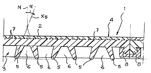
Description of the Preferred Embodiments
As may be appreciated by a comparison between Figure 1 and
Figure 2, an important characteristic of the solution according
to the invention is provided by the fact that the ribs 5 are
not arranged with their principle direction of extension
orthogonal with respect to the treading layer 2, but rather
generically inclined with respect to that layer. By "direction
of extension" is of course meant the direction along which the
ribs 5 (or, more precisely, their cross-sectional
CA 02317279 2000-08-29
6
profiles) extend as they depart from the treading layer
2.
In particular, the ribs 5 extend with their
respective direction of extension oblique with respect
to the surface of the treading layer. More precisely,
the ribs 5 are arranged with their general direction of
extension X5 forming an angle a with respect to the
direction of the normal N to the general plane of
extension of the treading layer 2. The value of the
angle a is chosen within a range which typically
extends from about 100 to about 30 , with a
preferential choice of between about 18 and about 20 .
In particular, it may be noted that in the
embodiment at present preferred the ribs 5 are not all
inclined in the same direction (i.e., monotonically)
with respect to the treading layer 2. Whilst the value
of the angle a preferably remains within the range
referred to above, the direction of inclination
alternates; i.e., with the angle a that changes sign in
an alternating sequence as the flooring is ideally
traversed in its plane of extension and in a direction
perpendicular to the direction of extension of the ribs
5.
At least in principle, the sequence of alternation
of the angle of inclination could be different from the
one illustrated, in which each rib 5 presents a
direction of inclination opposite to that of the two
adjacent ribs 5 (that is, if we refer to the sign of
the angle a, the sequence to which Figure 2 refers is a
sequence of the type +a, -a, +a, -a, etc.). The
sequence of alternation could be, however, of a
different type, for example with pairs of adjacent ribs
5 having a direction of inclination that is the same,
set between pairs of adjacent ribs having an opposite
direction of inclination (i.e., following a sequence of
CA 02317279 2000-08-29
7
the type +a, +a, -(X, -a, +a, +a, -a, -a, etc.) . Of
course, also non-symmetrical sequences of alternation
could be proposed (for example, +a, -a, -a, +a, -a, -a,
etc.).
More in general still, also the fact that there is
an alternation in the direction of inclination, albeit
constituting a preferential characteristic, does not
represent an indispensable element of the invention.
Hence, the ribs 5 could also be all inclined in the
same direction, as is envisaged in the solution
described in EP-A-0 913 524.
As compared to the solution described in this
previous application and also to the solution according
to the prior art represented in Figure 1, the solution
according to the present invention, as this is
represented in Figure 2, also presents the further
characteristic given by the fact that the ribs 5 are,
as a whole, quite slender, and hence thin above all at
their distal margins, which are designed to co-operate
directly with the substrate on which the flooring is
laid. It will be appreciated that distal margins of
this kind are usually at least slightly protruding with
respect to the corresponding margins of the ribs 6.
Preferably, the necessary characteristics of
slenderness, and hence of flexibility, referred to
above are achieved by giving to the ribs 5 a generally
tapered pattern (preferably with a triangular profile,
or quasi-triangular profile), which makes it possible
(to provide an immediately perceptible reference) to
liken them to the lip parts of windscreen-wiper blades.
In this way, it is possible to make the ribs 5, and
in particular their distal parts, so that they bend
(thanks to their general inclined arrangement) as soon
as the flooring 1 is laid on the corresponding
substrate in order to achieve a lip connection with the
CA 02317279 2000-08-29
8
substrate itself, the purpose being to get each portion
of the bottom face of the flooring 1 (see Figure 3)
between two adjacent ribs 5 and two correspondingly
adjacent ribs 6 to constitute a sucker-type formation
(of a generally rectangular shape, in the embodiment
illustrated) that is able to co-operate with the
substrate so as to provide firm anchorage of the
flooring 1 on the substrate itself even in the absence
of an adhesive layer (hence, working in conditions of
free laying).
It will be appreciated that the above-mentioned
sucker effect is obtained both in the regions of the
underside of the flooring delimited by diverging ribs 5
and in the portions delimited by converging ribs 5. It
is very likely (the applicant has, however, at the
moment not conducted specific investigations into the
matter) that the action occurs to a slightly greater
extent at the sections delimited by divergent ribs 5.
In any case, it will be appreciated that the effect
of sucker-type co-operation with the substrate develops
on the underside of the flooring (the one more clearly
visible in Figure 3) over the entire development of the
flooring itself, hence preventing the drawbacks
illustrated in the introductory part as being linked to
the use of foot-type formations.
Since the ribs 5 are arranged generically inclined
with respect to the treading layer 2 and are preferably
slender at least in their distal parts, they afford a
rather limited resistance to the loads applied
vertically on the flooring 1 starting from the treading
layer 2. It may thus be said that the ribs 5 play a
generally modest role in defining the overall
characteristics of compliance of the flooring 1.
This role is instead performed by the other ribs 6,
which extend in a direction orthogonal to the ribs 5,
CA 02317279 2000-08-29
9
preferably both in a direction orthogonal to the ribs 5
themselves and at fixed distances apart, said distances
being identified by d in Figure 3.
In this connection, it is to be noted that this
specific embodiment, although at the moment preferred,
is of itself not imperative for the purposes of the
implementation of the invention, given that the ribs 6
could extend also in inclined directions (for example,
following a zigzag or serpentine pattern) with respect
to the ribs 5, which could be distributed also at non-
uniform distances apart, possibly to vary selectively
the characteristics of compliance of the flooring from
one area to another.
In any case, for reasons of simplicity of
illustration, the principle lying at the basis of the
invention will now be illustrated with reference to the
embodiment shown in Figures 2 and 3.
As has already been said, both on account of their
inclined arrangement and on account of their
slenderness, the ribs 5 do not play a determining role
in identifying the characteristics of compliance of the
flooring 1. These characteristics are, instead,
identified by the ribs 6, and in particular by the
profile and spatial distribution of the same.
The ribs 6 extend in a direction orthogonal to the
treading layer 2, consequently not in an inclined
direction as do the ribs 5. Furthermore, they present a
preferably more massive structure, as compared to the
ribs 5.
This means that the mechanism of reaction of the
ribs 6 with respect to the vertical loading stresses
applied on the flooring 1 is substantially different
from that of the ribs 5. The ribs 6 are, in fact,
loaded perpendicularly as a result of the stress
applied on the flooring, and hence primarily determine,
CA 02317279 2000-08-29
on account of their characteristics of deformation
(cross section, profile, constitutive material, etc.)
and their spatial distribution (basically their
distribution density, and hence the distance d), the
5 characteristics of compliance of the flooring.
The fact that the aforesaid characteristics are
identified primarily by the ribs 6 makes possible a
convenient experimental check, since it can in fact be
verified that, all other factors being equal (and, in
10 particular, given the same dimensions, distribution,
density, and angle of inclination of the ribs 5), it is
possible to get the degree of compliance of the
flooring 1 to vary in a controlled manner by
intervening solely on the distribution density of the
formations 6 (for example, on their distance apart d)
and/or on the characteristics of deformability of the
formations 6 themselves.
The experiments carried out by the applicant show
that this result is achieved in an even more effective
way by setting a stabilization structure 7 between the
treading layer 2 and the ensemble of supporting ribs 3,
the said stabilization structure 7 consisting, for
example, of a stabilizing mesh made up, for instance,
of polyolefin fibres, such as polyester fibres.
In addition to exerting, in accordance with
criteria known in themselves, a stabilizing action in
regard to the treading layer 2, the stabilization
structure 7 unexpectedly plays a significant role in
causing the characteristics of compliance of the
flooring to be dictated primarily by the ribs 6. Albeit
not wishing to tie down to any specific theory in this
regard, the applicant believes that this action is very
probably linked to the fact that the stabilization
structure 7, characterized primarily by a considerable
resistance to tensile stresses, is able to perform an
CA 02317279 2000-08-29
11
action of connection between adjacent ribs 6, so
favouring the uniform distribution of the stresses
applied to the ribs themselves as a result of a load
that bears upon the flooring 1.
On the other hand, the stabilization structure 7
with all likelihood plays a similar role also in regard
to the ribs 5 by causing the action of connection to
the substrate achieved by the ribs 5 to be exerted in
an extremely uniform way over the entire development of
the flooring 1, further preventing the risk of
occurrence of undesired phenomena of local detachment
from the floor foundation.
Preferably, the flooring 1 according to the
invention is made starting from mixtures of synthetic
rubbers through one or more cascaded calendering
operations.
In particular, the flooring in question may be
obtained using the same materials currently used for
making similar floorings according to the prior art,
applying a process of single-layer or multi-layer
calendering generally identical to those adopted for
producing floorings according to the known art.
Of course, in the presently preferred embodiment of
the invention, it is necessary to envisage the step of
inserting a mesh functioning as a stabilization
structure 7. In any case, the insertion of such a
structure is carried out according to known criteria,
such as not to require a specific description herein.
In particular, a flooring of the type illustrated
in Figures 2 and 3 may be made using the same materials
currently used for making similar floorings according
to the prior art (in this connection, see what has been
said in the introductory part of the present
description with reference to Figure 1), adopting a
single-layer or multi-layer calendering process that is
CA 02317279 2000-08-29
12
basically identical to those used for the production of
floorings according to the prior art. The result of
providing the ribs, and in particular the ribs 5 (as
has been seen, the ribs 6 conserve a pattern that is
generically orthogonal to the treading layer 2) with
the desired angle may be obtained according to a
solution that has been tested with complete success by
the applicant, simply by providing, as regards the
calendering roller for sculpturing the supporting ribs
3, grooves or slits corresponding to and complementary
to the ribs 5 having their principal direction of
extension, in the direction of depth, oriented in a
direction that is at least slightly skewed with respect
to the corresponding diameter of the calendering
roller.
Purely to provide a non-limiting indication, the
flooring 1 illustrated in Figure 1 may present the
following characteristics:
- thickness (measured between the surface 4 of the
treading layer 2 and the distal margins of the ribs 5):
12.5 mm;
- overall thickness of the assembly made up of the
treading layer 2 and the plane part comprised between
the ribs 5 and 6: 6-7 mm;
- dimensions and shape of the plane of section of
the ribs 5: basically resembling a scalene triangle
having a base of 3.5 mm, and a distance between the
centre of the base and the vertex of approximately 6
mm; and
- inclination of the principal axis of the ribs
with respect to the treading layer 2 (angle a in Figure
2): approximately 18.5 .
The ensuing Table 1 gives the various values of
compliance (i.e., the coefficient KA measured according
to the DIN 18032/2 Standard) measured for the flooring
CA 02317279 2000-08-29
13
1 having the characteristics specified above, obtained
starting from a mix comprising, for the treading layer
2, a mixture of synthetic rubber (hardness, approx. 70
Shore A), and for the supporting formations 3, a
mixture of synthetic rubber (hardness approx. 55 Shore
A), with the interposition of a polyester-fibre mesh 7
between the two layers.
In particular,, the various values of compliance
were measured as a function of different values of the
distance of separation (d in Figure 3) between the ribs
6, referring to ribs 6 having a height (measured in a
direction orthogonal to the treading layer 2) of
approximately 6 mm, and a width of the base of 3 mm
with a pattern that is at least slightly tapered
towards the distal margin.
TABLE 1
DISTANCE d (mm) %KA
29
32
36
37.5
39
The various samples of flooring made according to
the criteria described above have shown, on the other
20 hand, a substantially identical behaviour as regards
anchorage to the substrate (achieved by free laying,
hence without any adhesive connection) and an
absolutely homogeneous behaviour as regards compliance
over the entire surface of the flooring, and
25 consequently without the formation of more or less
CA 02317279 2000-08-29
14
resistant surface areas that might possibly be detected
by treading.
From what has been described herein it is evident
that the solution according to the invention enables
the characteristics of compliance of the flooring to be
rendered altogether independent of the characteristics
of interaction with the substrate on which the flooring
is laid, with the consequent possibility of varying
selectively, even with a high degree of precision, the
values of compliance, it being possible moreover to
rely on a behaviour of the flooring determined and
reproducible in a deterministic way as regards the
characteristics of laying and of interaction with the
substrate.
It has in particular been possible to note that, at
the same time as being able to count on a complete
interaction, as well as an interaction that is
distributed in a uniform way between the underside of
the flooring 1 and the surface of the substrate on
which the flooring is laid, the flooring according to
the invention does not give rise to particular problems
when it is required to remove the flooring by lifting
it up from the substrate. The flooring may in fact be
easily removed simply by lifting up the sheets of which
it is normally made at one side and rolling it up
gradually. This is possible in so far as the sucker-
type relationship of co-operation with the substrate
described previously is achieved primarily (in a
precise and reliable way) when the flooring is
subjected to loads, in particular to treading loads,
without there being, on the other hand, any undesired
residual phenomena of connection of interaction when
the flooring, when not subjected to loads, is to be
removed.
From the foregoing it is evident that the invention
CA 02317279 2000-08-29
enables an assortment of floorings to be obtained
characterized by different values of compliance
depending primarily upon a different characteristic of
at least one property of the ribs of said second array
5 6, the floorings 1 of the assortment being, otherwise,
basically identical to one another.
Preferably, as has been seen previously, the said
at least one characteristic of a property is
represented by the spatial density of the ribs of the
10 second array 6.
Preferably, the flooring according to the invention
is made in the form of sheets, for example having a
width of approximately 130 cm. The sheets, set side by
side when the flooring is laid, may then be connected
15 together by means of elements, for instance of plastics
material (polypropylene, polyethylene, etc.) having a
C-shaped cross section or the like, designed to co-
operate with respective pairs of protruding ribs 8 made
on the bottom face of the flooring along the
longitudinal edges of the sheets, as illustrated in
Figure 3.
Of course, without prejudice to the principle of
the invention, the details of construction and the
embodiments may vary widely with respect to what is
described and illustrated herein, without thereby
departing from the scope of the invention.