Note: Descriptions are shown in the official language in which they were submitted.
CA 02317512 2000-09-07
PATENT
540593-2003
MEMORY SUPPORT CARD
BACKGROUND OF THE INVENTION
A. Field of the Invention
The present invention relates to a support card for a data storage unit, and
more
particularly, to an engagement member for engaging the support card to the
data storage unit.
B. Related Art
It is known that there are various types of cards of standardized rectangular
shape,
such as the standardized rectangular shape of credit cards or telephone
carfls, for example, which
are typically formed of a plate-like or flat support of plastic material which
includes a digital
memory unit.
In a first known type of card, the digital memory essentially consists of a
magnetic band extending over one of the two opposite faces of the flat body,
which is parallel to
one of the major sides of the flat body.
In a second known type of card commercially known as a "Smart Card", the
digital memory is essentially composed of a microchip incorporated into the
thickness of the flat
body. This microchip in a "Smart Card" has contact elements exposed on one of
the faces of the
flat body.
Recently, cards of standardized rectangular shape have been proposed in which
the digital memory is of the optical type, i.e. of the type commonly utilized
in manufacturing
compact discs. These cards which store optical memory are described for
example in Patent
Applications JP 4040586 and WO 99/00765.
The structure of those known cards storing optical memory do not have
important
differences in comparison to the features usually employed in known compact
discs. Therefore,
mrh1410
CA 02317512 2000-09-07
PATENT
540593-2003
the features of the known cards storing optical memory essentially are the
same as the features of
a compact disc of rectangular configuration, in which the area intended for
data storage is
bounded by an annulus substantially tangent to the major sides of the card and
concentric with a
through opening disposed at a centered position on the card.
Appropriate centering elements, for example, in form of ridges in the shape of
an
arc of a circle or projections of different shapes, are arranged on a reading
face of the card.
Those centering elements are intended to rest on an extractable tray of a
typical reading unit for
compact discs in order to correctly position the card on the tray. r
OBJECTS OF THE INVENTION
It is therefore an object of the present invention to provide an improved
storage
card in comparison to be known storage cards of the prior art.
It is also an object of the present invention to provide a storage card with
significantly improved versatility of use and memory capabilities as compared
with the storage
cards of the known art.
It is a further object of the present invention to provide a support card
which can
be used in conjunction with a storage data unit supported thereby.
It is further an object of the present invention to provide a support card
which can
be used in conjunction with several memory units even of different kinds on
one and the same
card.
It is a further object of the present invention to provide a storage card
wherein at
least one of the memory units is omitted, removed and/or replaced by combining
that unit with
the card.
MRH1410
CA 02317512 2000-09-07
PATENT
540593-2003
Various other objects, advantages and features of the present invention will
become readily apparent from the ensuing detailed description and the novel
feature will be
. particularly pointed out in the appended claims.
SUMMARY OF THE INVENTION
In accordance with the present invention, the foregoing and further objects
are
attained by a support card for data storage unit, which includes a plate-like
support having a
perimetral edge of a substantially rectangular profile having minor sides and
major sides and
which separates respective opposite first and second faces. The plate-
like,support also includes a
through opening extending through the first and second faces. In the present
invention, at least
the first face is coupled to a data storage unit which circumscribes the
through opening. Further,
an engagement member for engaging the data storage unit on the support card is
disposed on the
first face at the through opening of the support card.
BRIEF DESCRIPTION OF THE DRAWINGS
Further features and advantages of the present invention will become more
apparent from the detailed description of a preferred but non-exclusive
embodiment of a support
card for a data storage unit in accordance with the present invention. This
description will be
taken hereinafter with reference to the accompanying drawings, given by way of
a non-limiting
example, in which:
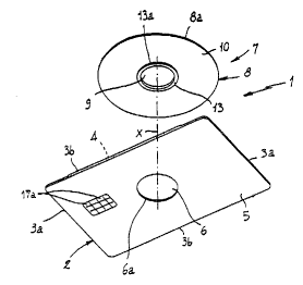
Fig. 1 is an exploded perspective bottom view of a preferred embodiment of a
support card in accordance with the present invention.
Fig. 2 illustrates the card of Fig. 1 with the optical memory unit mounted on
the
flat support thereof.
3 ~t,iaio
CA 02317512 2000-09-07
PATENT
540593-2003
Fig. 3 illustrates an enlarged view relative to Figs. 1 and 2 of a flat
support of the
cards as viewed from the opposite side relative to Fig. 1.
Fig. 4 is an exploded perspective top view of a support card in accordance
with a
second preferred embodiment of the invention.
Fig. 5 illustrates the card of Fig. 4 in an assembled condition.
Fig. 6 illustrates an enlarged view of a flat support of the card shown in
Figs. 4
and 5.
Fig. 7 is a sectional taken along line VII-VII of Fig. 2, shoving the coupling
between a first memory unit and the flat support, in accordance with
a.preferred embodiment of
the present invention.
Fig. 8 illustrates an alternate embodiment with respect to the coupling
between a
first memory unit and the flat support of Fig. 7.
Fig. 9 is a sectional view taken along line IX-IX of Fig. S, showing a
different
embodiment for achieving coupling between the first memory unit and the flat
support.
Fig. 10 illustrates an alternative embodiment in respect of Fig. 8.
DETAILED DESCRIPTION OF CERTAIN PREFERRED EMBODIMENTS
With reference to the drawings, a support card for a data storage unit in
accordance with the present invention has been generally identified by
reference numeral 1.
Card 1 includes a flat support 2, preferably made of plastic material, having
a
perimetral edge of a substantially rectangular profile defined by minor sides
3a and major sides
3b preferably of standardized sizes, corresponding to those of a conventional
credit card.
The respective minor and major sides 3a, 3b of the perimetral edge 3a, 3b of
the
flat support 2 separate respective opposite first and second faces 4, 5. The
first and second faces
4 mrh 1410
CA 02317512 2000-09-07
PATENT
540593-2003
4, 5 have a through opening 6 preferably disposed at a centered position in
the flat support 2.
More particularly, the through opening 6 has a geometric axis "X" intersecting
the crossing point
between the diagonals in the rectangular configuration of the flat support 2.
The first face 4 is advantageously intended for carrying a first data storage
unit 7,
hereinafter referred to as the first storage unit, circumscribing the through
opening 6.
The first storage unit 7 is preferably of a disc-shaped type, i.e., the first
storage
unit 7 has a plate-like body 8 including a centering through hole 9 and at
least one data storage
area 10, preferably of the optical type. The data storage area 10 is disposerd
so as to form an
annulus extending concentric with the centering through hole 9 and
substantially tangent to the
major sides 3b of the flat support 2.
In particular, the first storage unit 7, or at least the plate-like body 8
thereof, is
preferably defined by one side half of a DVD (digital versatile disc). The
outer diameter of this
DVD disc-half substantially corresponds to the size of the minor sides 3a of
the flat support 2.
As used herein, the term "disc-half ' is intended to mean one of the two disc-
shaped elements that
are usually coupled in mutual superposed relationship to form DVDs in the
conventional manner
(see document EP 86640 for example and further explanation).
The plate-like body 8 preferably has a circular configuration, bounded by an
outer
circumferential edge 8a. However, the plate-like body 8 may also have a
different configuration,
such as a quadrangular shape for example, provided the plate-like body 8 is
contained within the
extension of the minor and major sides 3a, 3b of the perimetral edge of the
flat support 2.
As shown in Fig. 1, the means for engagement of the first storage unit 7 to
the flat
support 2 is disposed on the first face 4 of the flat support 2 at the through
opening 6. This
engagement means of the flat support 2, preferably comprising a surface recess
1 I formed on the
mrh1410
CA 02317512 2000-09-07
PATENT
S40S93-2003
first face 4 (see Fig. 4). The surface recess 11 is able to house the first
storage unit 7 when the
latter, through a locating surface 7a thereof, is brought into abutment on the
surface recess 11
(see, for instance Fig. 7).
Preferably, the shape of the surface recess 11 matches that of the first
storage unit
7 and its depth corresponds to the thickness of the first storage unit 7. In
this way, the first
storage unit 7, when housed in the surface recess 11, has a reading surface 7b
disposed flush with
the first face 4 of the flat support 2.
In_particular, in the embodiment shown, the surface recess ~ 1 has a generally
circular configuration and is defined by a circumferential ridge 12 forms
substantially tangent
to the major sides 3b of the flat support 2.
Advantageously, the engagement of the first storage unit 7 with the flat
support 2
further involves the aid of a mechanical-interfacing member. This mechanical
interfacing
member comprises, for example, a fitting element which provides for engagement
between the
storage unit and the support card 1, preferably in a removable manner.
This mechanical-interfacing means preferably includes a collar 13 projecting
axially from the locating surface 7a at the centering through hole 9 having an
inner diameter
con esponding to that of the centering hole usually provided in a conventional
compact disc or
DVD. Collar 13 defines a shoulder 13a facing away from the geometric axis of
the centering
through hole 9. Shoulder 13a is able to cooperate with an inner
circumferential edge 6a of the
through opening 6 to accomplish a tight mechanical-interference fit with the
opening 6.
In a preferential embodiment shown in Fig. 7, the shoulder 13a of the collar
13
has a substantially cylindrical configuration which is in the same
configuration as the inner
circumferential edge 6a of the through opening 6. The outer diameter of the
collar 13 is slightly
mrh 1410
CA 02317512 2000-09-07
PATENT
540593-2003
greater than the inner diameter of opening 6, so as to achieve a tight
interference fit of the collar
within the opening.
In accordance with an alternative embodiment of the present invention shown in
Fig. 8, it may be advantageous to provide that the shoulder 13a defined by
collar 13 and/or the
inner circumferential edge 6a of the through opening 6 can be of a truncated
conical form. In
this manner, the shoulder 13a defines an angled cut extending towards the flat
body 8, whereas
the inner circumferential edge 6a defines an angled cut extending towards the
second face 5 of
the flat support 2, Due to these angled cuts, a mechanical-interference snap
fitting of collar 13 in
opening 6 is achieved.
In order to make snap-fitting easier, radial cuts may be advantageously
arranged
at the collar 13 andlor the opening 6. These cuts divide the collar 13 and/or
the inner
circumferential edge 6a into a plurality of elastically deformable portions in
the form of an arc of
a circle.
In a different embodiment, shown in Figs. 4, 5, 9 and 10, instead of the
collar 13
being associated with the first memory unit 7, at least one grip lug 14 can be
formed at the inner
circumferential edge 6a of the through opening 6. This grip lug 14, preferably
having an annular
configuration concentric with the through opening 6, defines a coupling ridge
14a facing away
from the geometric axis X of the through opening 6. This coupling ridge 14a
engages by
interference fit the centering hole 9 arranged in the first storage unit 7. In
this embodiment, the
through opening 6 has the same inner diameter as the centering hole usually
provided in compact
discs or DVDs, whereas the centering hole 9 arranged in the first storage unit
7 will have a
conveniently larger diameter.
7 mrh1410
CA 02317512 2000-09-07
PATENT
540593-2003
In the embodiment of Figs. 4, 5, 9 and 10, both the grip lug 14 and the
centering
hole 9 may have a cylindrical configuration, with the diameters thereof
slightly differentiated
from each other to cause mutual coupling by forced fitting (See Fig. 9).
Alternatively, the grip
lug 14 and/or centering hole 9 may be of a truncated conical form as shown in
Fig. 10, so as to
define mutually opposite angled cuts extending towards the second face 5 of
the flat support 2
and the reading surface 7b of the first storage unit 7, respectively.
In addition to, or in place of the collar 13 and/or the grip lug 14, the outer
circumferential edge 8a of the plate-like body 8 and the circumferential ridge
12 of the surface
recess 11 can be arranged such that the flat support 2 and the first
storag~unit are mutually
engaged by a mechanical-interference fit. Here, the outer circumferential edge
8a and the
circumferential ridge 12 may have a cylindrical configuration, with
differentiated diameters to
obtain a forced coupling of the plate-like body 8 within the surface recess
11. Alternatively, the
outer circumferential edge 8a and/or the circumferential ridge 12 may have, at
least as part of
their circumferential extension, a frusto-conical configuration, to form
mutually opposite angled
cuts extending towards the reading surface 7b and the surface recess 1 l,
respectively.
A centering member 15, 16 may also be included in the support card 1 for
centering of the flat support 2 in a known reading and/or data recording
device (not shown) for
the first storage unit 7. Advantageously, this centering member 1 S, 16 rnay
include centering
shoulders 1 S defined by auxiliary surface recesses 16, of a curved profile
for example, formed in
the first face 4 close to the minor sides 3a of the perimetral edge of the
flat support 2.
In addition, the support card 1 may advantageously include at least one
additional
data storage unit 17 accessible from the second face 5 of the flat support 2.
This additional
storage unit 17 can be advantageously made in the form of a microchip
incorporated into the flat
mrh1410
CA 02317512 2000-09-07
PATENT
540593-2003
support 2 within a seat arranged therein. In addition, this microchip has
contact elements 17a
exposed from the second face 5.
The present invention achieves its aforementioned intended purposes.
Unlike the known art, in which any type of memory must necessarily be part of
a
single unit provided on the flat support of the card, the present invention
enables a memory unit,
in particular of the optical type, to be coupled or associated on the card,
subsequent to production
of the card. This creates new possibilities for use of the cards as digital
memory media.
In.particular, a support card can be provided with a fixed digital storage
unit, of
the microchip type, for example. In this card, an optical memory can be-
optionally
interchangeable with a digital memory, depending upon need.
An optical memory made in the form of one side half of a DVD disc can also
advantageously coexist with a microchip memory even if, as it appears from the
depicted
examples, these memories extend over mutually superposed regions on the flat
support. This
would not be possible if the optical memory were in the form of a compact
disc. With a compact
disc, due to the thickness of the memory corresponding to the overall
thickness of the card, the
microchip memory would penetrate into regions intended for receiving optical
data.
On the contrary, due to the use of one side half of a DVD disc of a thickness
of
approximately 0.6 mm, a sufficient thickness is left free in the flat support
for containing the
microchip without the microchip memory projecting in the surface recess 11 and
thereby
occupying regions intended for optical memory. Further, due to dimensional
standardization of
the cards of the type in reference, the thickness of the card must not exceed
1.2 mm, of which the
thickness of the microchip memory only encompasses about 0.5 mm.
mrh1410
CA 02317512 2000-09-07
PATENT
540593-2003
It should be also appreciated that since several memory units can be
integrated
into one and the same card, an increased amount of data storable on the card
can be attained. In
addition, with use of a DVD optical memory, storage capacities close to about
1 GB can be
easily obtained.
Although the invention has been particularly shown and described with
reference
to certain preferred embodiments, it will be readily appreciated by those or
ordinary skill in the
art that various changes and modifications may be made therein without
departing from the spirit
and scope of the ~.nyention. It is intended that the appended claims be
interpreted as including
the foregoing as well as other such changes and modifications.
mrniaio