Note: Descriptions are shown in the official language in which they were submitted.
CA 02317553 2000-07-04
PCT/NZ99/00001
Received 13 October 1999
1
A DRILL PIPE AND METHOD OF FORMING AND RECONDITIONING A
DRILL PIPE
Technical Field
The present invention relates to a drill pipe, a method of forming drill pipe
and drill pipe formed thereby as well as to a method of reconditioning drill
pipe formed by conventional methods.
Background to the Invention
Some currently available torque and drag reducing tools used in drilling
applications installed directly onto drill pipes. Such tools may rotate about
the drill pipe to reduce rotational torque. As the outer surface of standard
drill pipe is neither perfectly round nor smooth, such tools have
compromised torque reduction performance. Additionally, the fluid film
operational principle of such tools sees drilling fluid, containing abrasive
drill cuttings, passing between the tool and the drill pipe. This creates
wear on the drill pipe and may compromise the strength of the drill pipe,
particularly as the wear patterns can be deep circumferential grooves
which may act as stress raisers in the tubular wall.
Disclosure of the Invention
The object of the present invention is to provide a drill pipe having an
integrally formed journal area having improved hardness, roundness and
smoothness and methods of forming a journal on a drill pipe, or to at least
provide the public with a useful choice.
According to a first aspect of the invention there is provided a drill pipe
having coupling sections at either end thereof:
a pair of stop collars integrally formed with the drill pipe and
extending radially outward; and
AMEN-DED SHEET
IpEA/AU
CA 02317553 2000-07-04
PCT/NZ99/00001
Received 3 February 2000
2
wherein a hardfacing material has been applied to the outer
surface of the drill pipe between the stop collars to form a journal for
supporting a rotating tool.
According to a further aspect of the invention there is provided a set of
drill pipes as hereinbefore described wherein the stop collars of the drill
pipes are located at different positions along the drill pipes to facilitate
efficient stacking of the drill pipes.
According to a further aspect of the invention there is provided a
combination comprising a drill pipe as hereinbefore described and a drilling
tool. The length of the journal is sufficiently longer than the length of the
drilling tool to facilitate lubrication and cooling of the interface between
the journal and the tool to reduce friction therebetween.
According to another aspect of the invention there is provided a method of
forming a journal on a drill pipe during manufacture comprising the steps
of:
i/ applying a hardfacing material to a section of the drill pipe
between a pair of intregally formed stop collars prior to heat
treating the drill pipe,
ii/ heat treating the drill pipe; and
iii/ precision grinding the section to which the hardfacing material has
been applied to form a smooth journal surface on the drill pipe.
The hardfacing is preferably an amorphous type hardfacing. The
hardfacing may be applied by high velocity oxy fuel, plasma spray,
combustion powder, combustion wire, arc wire spraying, flame thermal
spray, nitriding, carburising or other case hardening techniques.
Alternatively, the hardfacing may be a ceramic material or PDC
(polycrystalline diamond compact).
According to another aspect of the invention there is provided a method of
forming a journal on a section of preformed drill pipe comprising:
CA 02317553 2005-11-09
3
i/ lightly machining a section of the drill pipe between a pair of
intregrally formed stop coliars;
ii/ applying a hardfacing material to the section of the drill pipe; and
iii/ grinding the hardfaced section so that it is round and smooth.
The hardfacing material is preferably applied by spluttering, for example by
twin arc or high velocity oxy fuel spraying the hardfacing material directly
onto the existing drill pipe. The hardfacing material is preferably
ARMORCOR M or ARNCO with options being Rolls Wood or other suitable
materials.
There is further provided a drill pipe having coupling sections at either end
thereof and a journal formed on the drill pipe between said coupling
sections, the ovality of the journal being less than or equal to 0.7 mm.
According to an aspect of the invention there is provided a drill pipe having
coupling
sections at either end thereof and a journal formed on the pipe between said
coupling
sections, wherein the journal has a surface hardness of greater than or equal
to 35 Rc.
According to another aspect of the invention there is provided a drill pipe
comprising
coupling sections at either end thereof, and a pair of stop collars integrally
formed with
the drill pipe and extending radially outward, wherein a surface of the pipe
between that
stop collars has a roughness of less than 0.8 micrometers to form a journal
for supporting
a rotating tool.
Brief Description of the Drawings
The invention will now be described with reference to the accompanying
drawings in which:
Figure 1 a: shows a partial sectional side view of drill pipe with an
integrally formed journal surface;
CA 02317553 2005-11-09
3a
Figure 1 b: shows a partial sectional side view of a drill pipe with a
drilling tool secured thereto;
Figure 1 c: shows a partial sectional side view of a drill pipe having
separate stop collars fitted thereto;
Figure 2: shows a section of conventional drill pipe;
Figure 3: shows the drill pipe of figure 2 after machining;
Figure 4: shows the application of a hardfacing material to the drill
pipe shown in figure 3;
CA 02317553 2000-07-04
WO 99/35366 4 PCT/NZ99/00001
Figure 5: shows the drill pipe of figure 4 after grinding.
Best Mode for Carrying out the Invention
Referring to figure la there is shown a drill pipe 1 having an integrally
formed journal generally indicated by the numeral 2. The drill string has a
female coupling section 3 at one end, a male coupling section 4 at the
other end and a pipe section 5 therebetween.
IU
Female coupling 3 and male coupling 4 are preferably formed by forging
and are friction welded to respective ends of pipe section 5 at areas 6 and
7. The thickness of the drill pipe is seen to vary gradually from female
coupling 3 and male coupling 4 to pipe section 5 at points 8 and 9. This
gradual tapering avoids the creation of a stress point at a rapid transition.
Integrally formed collars 10 and 11 define a journal surface 12
therebetween.
The pipe string is formed substantially in accordance with standard
procedures apart from the procedures for forming journal 2. Female
portion 3 and male portion 4 (including journal 2) are formed by forging
and are friction welded to pipe section 5. Male fitting 4 is forged in a
shape including collars 10 and 11 and journal surface 12.
Prior to heat treating the drill pipe in a standard forming procedure an
amorphous type hardfacing material is applied to journal surface 12. The
hardf acing surface may be formed on journal surface 12 using case
hardening techniques, such as nitriding or carburising. Alternatively high
velocity oxy fuel, plasma spray, combustion powder, combustion wire, arc
wire spraying, or flame thermal spray techniques may be used.
Alternatively, a ceramic layer or a PDC (polycrystalline diamond compact)
layer may be applied.
CA 02317553 2000-07-04
WO 99/35366 5 PCT/NZ99/00001
The drill pipe is then heat treated in the normal manner. The journal
surface 12 of the drill pipe so formed is then precision ground to form a
smooth round journal surface upon which a tool may be fitted. As collars
and 1 1 are integrally formed during manufacture of the drill pipe 1 no
5 additional collars need to be provided. Due
to the smoothness of journal 12 the problems associated with fitting tools
directly to drill pipes encountered in the prior art may be substantially
overcome.
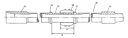
10 Referring now to figure lb there is shown a drill pipe 19 having male and
female coupling sections 13 and 14 at either end thereof. Journal 15 is
located at a central region of the drill pipe 19 and stop collars 16 and 17
are integrally formed with drill pipe 19 at either end of journal 15. A
rotatable drilling tool 18 is secured about journal 15. A rotatable drilling
tool 18 may be a multi-part drilling tool as described in WO 96/34173, or
similar, which is able to be secured about journal 15 in use.
The length b of journal 15 is preferably sufficiently greater than the length
a of rotatable drilling tool 18 to allow effective lubrication and cooling of
the interface between journal 15 and rotatable drilling tool 18. Length b is
preferably at least 20% greater than length a, preferably length b is more
than 35% greater than length a, more preferably length b is more than
50% greater than length a. By allowing the rotatable drilling tool 18 to
move along joumal 15 lubricant may be introduced to the interface
between journal 15 and rotatable drilling tool 18 as well as allowing heat
to dissipate from journal 15, thus reducing wear.
In the embodiment shown in figure lb collars 16 and 17 are provided at a
central location along drill pipe 19. In the embodiment of figure 1 a the
stop collar 10 and stop collar formed by male coupling section 11 were
provided at one end of the drill pipe 1. By providing a set of drill pipes
having the collars located at different positions along the drill pipes the
drill
CA 02317553 2000-07-04
WO 99/35366 PCT/NZ99/00001
6
pipes may nestle together when stacked to achieve more efficient
stacking.
Referring now to figure 1 c there is shown a drill pipe 25 having male and
female coupling sections 26 and 27 at either end thereof. Journal 28 is
formed on drill pipe 25 and a rotatable tool 29 is mounted upon journal 28.
In this case moveable stop collars 30 and 31 are secured at either end of
journal 28. Stop collars 30 and 31 may be of two part construction so
that they can be secured to drill pipe 25 in use. This arrangement allows
the spacing between the stop collars to be varied depending upon the tool
secured to the drill pipe. It also simplifies the manufacture of drill pipe as
the stop collars do not need to be integrally formed, particularly for central
areas of the drill pipe. This approach is also applicable where a journal is
to be formed upon an existing section of drill string.
0
The journals of the drill pipes described in figuees 1 a to 1 c should be
round, hard and smooth to minimise wear of the journal surface and
rotatable tool. The surface of the tool should have a roughness of less
than 0.8 micrometres. The journal should have an ovality of less than or
equal to 0.7 mm, preferably less than 0.5 mm and more preferably less
than 0.25 mm. The journal should also have a surface hardness of greater
than or equal to 35 Rc, preferably greater than 38 Rc. The length of the
journal will typically be less than 3 metres. Methods of forming the
journals will be described in conjunction with figures 2 to 5 below.
When machining or treating preformed drill pipes care must be taken not
to heat the drill pipe in such a manner that it loses its temper. Referring
now to figures 2 to 5 a method of reconditioning a drill pipe is shown
schematically.
In figure 2 a drill pipe 20 is shown prior to reconditioning. In the first
step
shown in figure 3 a section 21 of the drill pipe is lightly machined,
preferably by rotating the drill pipe in a lathe relative to bit 22 which
CA 02317553 2000-07-04
WO 99/35366 PCT/1VZ99/00001
7
moves along the section 21. The extent of machining has been greatly
exaggerated for illustrative purposes.
In the next step shown in figure 4 a hardfacing material is applied. The
procedure used to form the hardfacing must not heat the drill pipe 20 in
such a manner as to affect its temper. One method is to apply material by
sptuttering, preferably by twin arc or high velocity oxy fuel spraying
hardfacing material 23 directly onto section 21 of the drill pipe. This
technique requires careful preheating of the drill pipe to a temperature
which is not so hot as to affect the temper of the pipe but not so cold that
the hardfacing will not be successfully applied. The hardfacing material 23
is deposited using a finely calibrated arc transfer pressure. A back-step
application technique may be required to ensure that the base material
temperature remains within acceptable limits.
Preferred hardfacing materials are ARMORCOR M or ARNCO. It will,
however, be appreciated that other suitable techniques or materials may
be employed as long as the above requirements are met.
In the final step, shown in figure 5, the hardfaced section 21 is ground by
aluminium oxide grinder 24 so that the journal surface 21 is round and
smooth. A drilling tool may then be installed onto the drill pipe in the
normal way. If required, collars may be provided at either end of journal
section 21.
The invention thus provides an improved drill pipe including an integrally
formed journal which enables rotatable toots to be directly mounted to the
journal surface resulting in decreased friction between the tool and the drill
pipe and minimising wear on the drill pipe.
There is also provided a method of reconditioning existing drill pipe to
provide a journal for receiving a tool which results in reduced friction
between the tool and the drill pipe and minimises wear on the drill.
CA 02317553 2000-07-04
WO 99/35366 PCT/NZ99/00001
8
Where in the foregoing description reference has been made to integers or
components having known equivalents then such equivalents are herein
incorporated as if individually set forth.
Although this invention has been described by way of example it is to be
appreciated that improvements and/or modifications may be made thereto
without departing from the scope of the present invention as defined in
the claims.