Language selection

Search

Patent 2317913 Summary

Third-party information liability

Some of the information on this Web page has been provided by external sources. The Government of Canada is not responsible for the accuracy, reliability or currency of the information supplied by external sources. Users wishing to rely upon this information should consult directly with the source of the information. Content provided by external sources is not subject to official languages, privacy and accessibility requirements.

Claims and Abstract availability

Any discrepancies in the text and image of the Claims and Abstract are due to differing posting times. Text of the Claims and Abstract are posted:

  • At the time the application is open to public inspection;
  • At the time of issue of the patent (grant).
(12) Patent: (11) CA 2317913
(54) English Title: SIDE FRAME-BOLSTER INTERFACE FOR RAILCAR TRUCK ASSEMBLY
(54) French Title: JOINT D'UNE TRAVERSE PIVOT D'UN LONGERON DE BOGIE POUR CHARIOT-DIABLE
Status: Deemed expired
Bibliographic Data
(51) International Patent Classification (IPC):
  • B61F 5/00 (2006.01)
  • B61F 5/12 (2006.01)
(72) Inventors :
  • SPENCER, CHARLES P. (United States of America)
(73) Owners :
  • AMSTED INDUSTRIES INCORPORATED (United States of America)
(71) Applicants :
  • AMSTED INDUSTRIES INCORPORATED (United States of America)
(74) Agent: GOWLING WLG (CANADA) LLP
(74) Associate agent:
(45) Issued: 2003-06-03
(22) Filed Date: 2000-09-07
(41) Open to Public Inspection: 2001-03-16
Examination requested: 2000-09-07
Availability of licence: N/A
(25) Language of filing: English

Patent Cooperation Treaty (PCT): No

(30) Application Priority Data:
Application No. Country/Territory Date
09/397,584 United States of America 1999-09-16

Abstracts

English Abstract


A three-piece railcar truck assembly is disclosed. The truck assembly has two
side
frames and a bolster extending between the side frames. Each side frame has
spaced columns
defining an opening which receives one end of the bolster. Each side frame
also has forward
and rearward lugs at the columns, both on the inboard side and the outboard
side. Each side
frame lug has a stop surface that is aligned in a facing relationship with a
stop surface of one
bolster gib. There is a gap between the opposed side frame lug and bolster gib
stop surfaces.
The gap distance is limited to limit the truck warp angle. The neighboring
side frame lugs and
bolster gibs may be sized, shaped and spaced so that the truck warp angle may
be limited to an
angle of less than two degrees. The various stop-surfaces may be hardened to a
desirable
range of hardness over at least the contact portion of either contacting lug
or gib, or both
contacting surfaces may be hardened above the as-cast hardness.


Claims

Note: Claims are shown in the official language in which they were submitted.


CLAIMS

I claim:

1. A three-piece railcar truck assembly comprising a bolster and a pair of
side frames,
said three-piece railcar truck assembly having a longitudinal axis and a
perpendicular
transverse axis;
each side frame having a longitudinal axis, a forward column and a rearward
column,
each forward column including an inboard forward column web, an outboard
forward column
web and a transverse forward column web between the inboard forward column web
and
outboard forward column web, each rearward column including an inboard
rearward column
web, an outboard rearward column web, and a transverse rearward column web
between the
inboard rearward column web and outboard rearward column web, each side frame
forward
column and rearward column cooperating to define an opening in said side frame
between the
transverse forward column web and transverse rearward column web, each side
frame further
including an inboard forward lug on the inboard forward column web, an inboard
rearward lug
on the inboard rearward column web, an outboard forward lug on the outboard
forward
column web, and an outboard rearward column lug on the outboard rearward
column web,
each side frame lug having a stop surface;
said bolster having a first end, a second end, a forward side and a rearward
side, a
forward inboard bolster gib and a forward outboard bolster gib at said bolster
forward side at
each said bolster first and second ends and a rearward inboard bolster gib and
a rearward
outboard bolster gib at said bolster rearward side at each said bolster first
and second ends,
each of said bolster ends matable with the opening in each side frame defined
by the forward
and rearward side frame columns, said forward inboard and outboard bolster
gibs at each
bolster end cooperating to define a clearance between said forward inboard and
outboard
bolster gibs greater than the width of the forward transverse column web of
the side frame
receiving the bolster end, said rearward inboard and outboard bolster gibs at
each bolster end
cooperating to define a clearance between said rearward inboard and outboard
bolster gibs

18


greater than the width of the rearward transverse column web of the side frame
receiving the
bolster end, said forward and rearward inboard and outboard bolster gibs each
having a stop
surface;
one inboard forward side frame lug and one inboard forward bolster gib at one
end of
the bolster defining an inboard forward neighboring side frame lug and bolster
gib;
one inboard rearward side frame lug and one inboard rearward bolster gib at
one end
of the bolster defining an inboard rearward neighboring side frame lug and
bolster gib;
one outboard forward side frame lug and one outboard forward bolster gib at
one end
of the bolster defining an outboard forward neighboring side frame lug and
bolster gib;
one outboard rearward side frame lug and one outboard rearward bolster gib at
one end
of the bolster defining an outboard rearward neighboring side frame lug and
bolster gib;
at least part of the stop surfaces of each neighboring side frame lug and
bolster gib
being in facing relationship and in proximity to each other;
the total of the distance between at least a part of the stop surfaces of the
inboard
forward neighboring side frame lug and bolster gib at one end of the bolster
and the distance
between at least a part of the stop surfaces of the inboard rearward
neighboring side frame lug
and bolster gib at the same end of the bolster being less than 3/16 inch; and
the total of the distance between at least a part of the stop surfaces of the
outboard
forward neighboring side frame lug and bolster gib at one end of the bolster
and the distance
between at least a part of the stop surfaces of the outboard rearward
neighboring side frame
lug and bolster gib at one end of the bolster being less than 3/16 inch.
2. The three-piece railcar truck assembly of claim 1 wherein the total of the
distance
between at least a part of the stop surfaces of the inboard forward
neighboring side frame lug
and bolster gib at one end of the bolster and the distance between at least a
part of the stop
surfaces of the inboard rearward neighboring side frame lug and bolster gib at
the same end of
the bolster is between 3/16 inch and 1/32 inch; and
19


the total of the distance between at least a part of the stop surfaces of the
outboard
forward neighboring side frame lug and bolster gib at one end of the bolster
and the distance
between at least a part of the stop surfaces of the outboard rearward
neighboring side frame
lug and bolster gib at the same end of the bolster being between 3/16 inch and
1/32 inch.
3. The three-piece railcar truck assembly of claim 1 wherein each bolster gib
has a
longitudinal limit surface substantially perpendicular to the bolster gib stop
surface and spaced
from and in facing alignment with one of the side frame column inboard and
outboard column
webs.
4. The three-piece railcar truck assembly of claim 1 wherein the distance
between at least
part of the stop surfaces of the inboard forward neighboring side frame lug
and bolster gib is
in the range of 3/64 - 1/64 inches.
5. The three-piece railcar truck assembly of claim 1 wherein the distance
between at least
part of the stop surfaces of the inboard rearward neighboring side frame lug
and bolster gib is
in the range of 3/64 - 1/64 inches.
6. The three-piece railcar truck assembly of claim 1 wherein the distance
between at least
part of the stop surfaces of the outboard forward neighboring side frame lug
and bolster gib is
in the range of 3/64 - 1/64 inches.
7. The three-piece railcar truck assembly of claim 1 wherein the distance
between at least
part of the stop surfaces of the outboard rearward neighboring side frame lug
and bolster gib is
in the range of 3/64 - 1/64 inches.

20


8. The three-piece railcar truck assembly of claim 7 wherein the distance
between at least
part of the stop surfaces of the inboard forward neighboring side frame lug
and bolster gib is
in the range of 3/64 - 1/64 inches, the distance between at least part of the
stop surfaces of the
inboard rearward neighboring side frame lug and bolster gib is in the range of
3/64 - 1/64
inches, and the distance between at least part of the stop surfaces of the
outboard forward
neighboring side frame lug and bolster gib is in the range of 3/64 - 1/64
inches.
9. A three-piece railcar truck assembly comprising a bolster and a pair of
side frames,
said three-piece railcar truck assembly having a longitudinal axis and a
perpendicular
transverse axis;
each side frame having a longitudinal axis, a forward column and a rearward
column,
each forward column including an inboard forward column web, an outboard
forward column
web and a transverse forward column web between the inboard forward column web
and
outboard forward column web, each rearward column including an inboard
rearward column
web, an outboard rearward column web, and a transverse rearward column web
between the
inboard rearward column web and outboard rearward column web, each side frame
forward
column and rearward column cooperating to define an opening in said side frame
between the
transverse forward column lug and transverse rearward column web, each side
frame further
including an inboard forward lug on the inboard forward column web, an inboard
rearward lug
on the inboard rearward column web, an outboard forward lug on the outboard
forward
column web, and an outboard rearward column web on the outboard rearward
column web,
each side frame lug having a stop surface;
said bolster having a first end, a second end, a forward side and a rearward
side, each
of said bolster ends matable with the opening in each side frame defined by
the forward and
rearward columns, said bolster further including a forward inboard bolster gib
and a forward
outboard bolster gib at said bolster forward side at each of said bolster
first and second ends
and a rearward inboard bolster gib and a rearward outboard bolster gib at said
bolster

21


rearward side at each of said bolster first and second ends, said forward
inboard and outboard
bolster gibs at each bolster end cooperating to define a clearance between
said inboard and
outboard bolster gibs greater than the width of the forward transverse column
web of the side
frame receiving the bolster end, said rearward inboard and outboard bolster
gibs at each
bolster end cooperating to define a clearance between said inboard and
outboard bolster gibs
greater than the width of the rearward transverse column web of the side frame
receiving the
bolster end, said forward and rearward inboard and outboard bolster gibs each
having a stop
surface;
said bolster having a bolster longitudinal axis corresponding with the railcar
truck
assembly transverse axis and generally normal to said railcar truck assembly
longitudinal axis
and said longitudinal axes of said side frames at a warp reference position;
angular displacement of said bolster longitudinal axis from the respective
warp
reference position defining a truck warp angle;
one inboard forward side frame lug and one inboard forward bolster gib at one
end of
the bolster defining an inboard forward neighboring bolster gib and side frame
lug;
one inboard rearward side frame lug and one inboard rearward bolster gib at
the same
end of the bolster defining an inboard rearward neighboring bolster gib and
side frame lug;
one outboard forward side frame lug and one outboard forward bolster gib at
the same
end of the bolster defining an outboard forward neighboring bolster gib and
side frame lug;
one outboard rearward side frame lug and one outboard rearward bolster gib at
the
same end of the bolster defining an outboard rearward neighboring bolster gib
and side frame
lug;
at least part of the stop surfaces of each neighboring bolster gib and side
frame lug
being in facing relationship and in proximity to each other;
the inboard forward neighboring bolster gib and side frame lug and the
outboard
rearward neighboring bolster gib and side frame lug being diagonally opposite;
22


the inboard rearward neighboring bolster gib and side frame lug and the
outboard
forward neighboring bolster gib and side frame lug being diagonally opposite;
wherein at least a part of the stop surfaces of each neighboring bolster gib
and side
frame lug are sized, shaped and spaced so that at least one of the outboard
neighboring bolster
gibs and side frame lugs and the diagonally opposite inboard neighboring
bolster gib and side
frame lug at the same bolster end limit rotation of the bolster about a
vertical axis to control
the truck warp angle.
10. The three-piece railcar truck assembly of claim 9 wherein both outboard
neighboring
bolster gibs and side frame lugs at one end of the bolster and the diagonally
opposite inboard
neighboring bolster gib and side frame lug at the same end of the bolster
limit rotation of the
bolster about a vertical axis to control the truck warp angle.
11. The three-piece railcar truck assembly of claim 9 wherein the truck warp
angle is
limited to an angle of about 2° or less.
12. The three-piece railcar truck assembly of claim 9 wherein the truck warp
angle is
limited to an angle in the range of about 0.2°- 2°.
13. The three-piece railcar truck assembly of claim 9 wherein the total of the
distance
between at least a part of the stop surfaces of the inboard forward
neighboring side frame lug
and bolster gib at one end of the bolster and the distance between at least a
part of the stop
surfaces of the inboard rearward neighboring side frame lug and bolster gib at
the same end of
the bolster is less than 3/32 inch; and
the total of the distance between at least a part of the stop surfaces of the
outboard
forward neighboring side frame lug and bolster gib at one end of the bolster
and the distance
23


between at least a part of the stop surfaces of the outboard rearward
neighboring side frame
lug and bolster gib at the same end of the bolster is less than 3/32 inch.
14. A three-piece railcar truck assembly comprising a bolster and a pair of
side frames,
said three-piece railcar truck assembly having a longitudinal axis and a
perpendicular
transverse axis;
ach said side frame having a longitudinal axis, a forward column and a
rearward
column, each forward column including an inboard forward column web, an
outboard forward
column web and a transverse forward column web between the inboard forward
column web
and outboard forward column web, each rearward column including an inboard
rearward
column web, an outboard rearward column web, and a transverse rearward column
web
between the inboard rearward column web and outboard rearward column web, each
side
frame forward column and rearward column cooperating to define an opening in
said side
frame between the transverse forward column lug and transverse rearward column
web, each
side frame further including an inboard forward lug on the inboard forward
column web, an
inboard rearward lug on the inboard rearward column web, an outboard forward
lug on the
outboard forward column web, and an outboard rearward column web on the
outboard
rearward column web, each side frame lug having a stop surface;
said bolster having a first end, a second end, a forward side and a rearward
side, each
of said bolster ends matable with the opening in each side frame defined by
the forward and
rearward columns, said bolster further including a forward inboard bolster gib
and a forward
outboard bolster gib at said bolster forward side at each said bolster first
and second ends and
a rearward inboard bolster gib and a rearward outboard bolster gib at said
bolster rearward
side at each said bolster first and second ends, each said forward inboard and
outboard bolster
gibs at each said bolster forward side cooperating to define a clearance
between said inboard
and outboard bolster gibs greater than the width of the forward transverse
column web of the
side frame receiving the bolster end, each said rearward inboard and outboard
bolster gibs at

24


each bolster rearward side cooperating to define a clearance between said
inboard and
outboard bolster gibs greater than the width of the rearward transverse column
web of the side
frame receiving the bolster end, said forward and rearward inboard and
outboard bolster gibs
each having a stop surface;
said bolster having a bolster longitudinal axis corresponding with the railcar
truck
assembly transverse axis and generally normal to said railcar truck assembly
longitudinal axis
and said longitudinal axes of said side frames at a warp reference position;
angular displacement of said bolster longitudinal axis from the warp reference
position
defining a truck warp angle;
one inboard forward side frame lug and one inboard forward bolster gib at one
end of
the bolster defining an inboard forward neighboring bolster gib and side frame
lug;
one inboard rearward side frame lug and one inboard rearward bolster gib at
the same
end of the bolster defining an inboard rearward neighboring bolster gib and
side frame lug;
one outboard forward side frame lug and one outboard forward bolster gib at
the same
end of the bolster defining an outboard forward neighboring bolster gib and
side frame lug;
one outboard rearward side frame lug and one outboard rearward bolster gib at
the
same end of the bolster defining an outboard rearward neighboring bolster gib
and side frame
lug;
at least part of the stop surfaces of each neighboring bolster gib and side
frame lug
being in facing relationship and in proximity to each other;
the inboard forward neighboring bolster gib and side frame lug and the
outboard
rearward neighboring bolster gib and side frame lug being diagonally opposite;
the inboard rearward neighboring bolster gib and side frame lug and the
outboard
forward neighboring bolster gib and side frame lug being diagonally opposite;
wherein the outboard forward bolster gib and outboard rearward bolster gib at
one end
of the bolster and the neighboring outboard forward side frame lug and the
neighboring
outboard rearward side frame lug have outboard limits, and wherein the
distances between the

25


longitudinal centerline of the railcar truck assembly and said outboard limits
of said side frame
lugs are at least as great as the distances between the longitudinal
centerline of said railcar
truck assembly and said outboard bolster gibs at the warp reference position;
and
wherein the inboard forward bolster gib and inboard rearward bolster gib at
one end of
the bolster and the neighboring inboard forward side frame lug and the
neighboring inboard
rearward side frame lug have inboard limits, and wherein the distances between
the
longitudinal centerline of the railcar truck assembly and said inboard limits
of said side frame
lugs are no greater than the distances between the longitudinal centerline of
the railcar truck
assembly and the inboard limits of said inboard bolster gibs at the warp
reference position.
15. The three-piece railcar truck assembly of claim 14 wherein the total of
the distance
between at least a part of the stop surfaces of the inboard forward
neighboring side frame lug
and bolster gib at one end of the bolster and the distance between at least a
part of the stop
surfaces of the inboard rearward neighboring side frame lug and bolster gib at
the same end of
the bolster is less than 3/32 inch; and
the total of the distance between at least a part of the stop surfaces of the
outboard
forward neighboring side frame lug and bolster gib at one end of the bolster
and the distance
between at least a part of the stop surfaces of the outboard rearward
neighboring side frame
lug and bolster gib at the same end of the bolster is less than 3/32 inch.
16. The three-piece truck assembly of claim 15 wherein the distance between at
least part
of the stop surfaces of the outboard rearward neighboring side frame lug and
bolster gib is in
the range of 3/64 - 1/64 inches, the distance between at least part of the
stop surfaces of the
inboard forward neighboring side frame lug and bolster gib is in the range of
3/64 - 1/64
inches, the distance between at least part of the stop surfaces of the inboard
rearward
neighboring side frame lug and bolster gib is in the range of 3/64 - 1/64
inches, and the

26


distance between at least part of the stop surfaces of the outboard forward
neighboring side
frame lug and bolster gib is in the range of 3/64 - 1/64 inches.
17. The three-piece truck assembly of claim 14 wherein at least a part of the
stop surfaces
of each neighboring bolster gib and side frame lug are sized, shaped and
spaced so that one of
the outboard neighboring bolster gibs and side frame lugs and the diagonally
opposite inboard
neighboring bolster gib and side frame lug limit rotation of the bolster about
a vertical axis to
control the truck warp angle.
18. The three-piece railcar truck assembly of claim 17 wherein the truck warp
angle is
limited to an angle in the range of about 0.2°- 2°.
19. The three-piece railcar truck assembly of claim 18 wherein the distance
between at least
part of the stop surfaces of the outboard rearward neighboring side frame lug
and bolster gib is
in the range of 3/64 - 1/64 inches, the distance between at least part of the
stop surfaces of the
inboard forward neighboring side frame lug and bolster gib is in the range of
3/64 - 1/64
inches, the distance between at least part of the stop surfaces of the inboard
rearward
neighboring side frame lug and bolster gib is in the range of 3/64 - 1/64
inches, and the
distance between at least part of the stop surfaces of the outboard forward
neighboring side
frame lug and bolster gib is in the range of 3/64 - 1/64 inches.
20. A three-piece railcar truck assembly comprising a bolster and a pair of
side frames,
said three-piece railcar truck assembly having a longitudinal axis and a
perpendicular
transverse axis;
each side frame having a longitudinal axis, a forward column and a rearward
column,
each forward column including an inboard forward column web, an outboard
forward column
web and a transverse forward column web between the inboard forward column web
and

27


outboard forward column web, each rearward column including an inboard
rearward column
web, an outboard rearward column web, and a transverse rearward column web
between the
inboard rearward column web and outboard rearward column web, each side frame
forward
column and rearward column cooperating to define an opening in said side frame
between the
transverse forward column web and transverse rearward column web, each side
frame further
including an inboard forward lug on the inboard forward column web, an inboard
rearward lug
on the inboard rearward column web, an outboard forward lug on the outboard
forward
column web, and an outboard rearward column lug on the outboard rearward
column web,
each side frame lug having a stop surface;
said bolster having a first end, a second end, a forward side and a rearward
side, a
forward inboard bolster gib and a forward outboard bolster gib at said bolster
forward side at
each said bolster first and second ends and a rearward inboard bolster gib and
a rearward
outboard bolster gib at said bolster rearward side at each said bolster first
and second ends,
each of said bolster ends matable with the opening in each side frame defined
by the forward
and rearward side frame columns, said forward inboard and outboard bolster
gibs at each
bolster end cooperating to define a clearance between said forward inboard and
outboard
bolster gibs greater than the width of the forward transverse column web of
the side frame
receiving the bolster end, said rearward inboard and outboard bolster gibs at
each bolster end
cooperating to define a clearance between said rearward inboard and outboard
bolster gibs
greater than the width of the rearward transverse column web of the side frame
receiving the
bolster end, said forward and rearward inboard and outboard bolster gibs each
having a stop
surface;
one inboard forward side frame lug and one inboard forward bolster gib at one
end of
the bolster defining an inboard forward neighboring side frame lug and bolster
gib;
one inboard rearward side frame lug and one inboard rearward bolster gib at
one end
of the bolster defining an inboard rearward neighboring side frame lug and
bolster gib;

28


one outboard forward side frame lug and one outboard forward bolster gib at
one end
of the bolster defining an outboard forward neighboring side frame lug and
bolster gib;
one outboard rearward side frame lug and one outboard rearward bolster gib at
one end
of the bolster defining an outboard rearward neighboring side frame lug and
bolster gib;
at least part of the stop surfaces of each neighboring side frame lug, and
bolster gib
being in facing relationship and in proximity to each other;
the total of the distance between at least a part of the stop surfaces of the
inboard
forward neighboring side frame lug and bolster gib at one end of the bolster
and the distance
between at least a part of the stop surfaces of the inboard rearward
neighboring side frame lug
and bolster gib at the same end of the bolster being less than 3/16 inch; and
the total of the distance between at least a part of the stop surfaces of the
outboard
forward neighboring side frame lug and bolster gib at one end of the bolster
and the distance
between at least a part of the stop surfaces of the outboard rearward
neighboring side frame
lug and bolster gib at one end of the bolster being less than 3/16 inch;
said bolster gibs and said side frame lugs having an as-cast hardness,
at least one of said bolster gib and side frame lug of each said neighboring
inboard and
outboard bolster gib and side frame lug at each said bolster first and second
ends flame
hardened to increase said hardness of said stop-surface of said at said at
least one bolster gib
and side frame lug to increase a wear rate of said stop-surface.
21. The three-piece railcar truck assembly of claim 20, wherein said bolster
gibs and said side
frame lugs have an as-cast hardness, said at least one flame-hardened gib and
bolster
stop-surfaces hardened to a hardness range between about 375 BHN and 515BHN to
a depth of
about twelve hundredths inch below said stop-surfaces.
22. The three-piece railcar truck assembly of claim 20, wherein said bolster
gibs and said side
frame lugs have an as-cast hardness between about 137BHN and 208 BHN,
29


said at least one flame-hardened gib and bolster stop-surfaces hardened to a
hardness
range between about 375 BHN and 515BHN to reduce the rate of wear on said at
least one
surface from contact with the other of said bolster gib and side frame lug
stop surface.
23. The three-piece railcar truck assembly of claim 20, wherein the distance
between at least
part of the stop surfaces of the outboard forward neighboring side frame lug
and bolster gib is
in the range of 3/64 to 1/64 inch;
the distance between at least part of the stop surfaces of the inboard
rearward
neighboring side frame lug and bolster gib is in the range of 3/64 to 1/64
inch, and the
distance between at least part of the stop surfaces of the outboard forward
neighboring side
frame lug and bolster gib is in the range of 3/64 to 1/64 inch,
said bolster gibs and said side frame lugs have an as-cast hardness between
about
137BHN and 208 BHN,
said at least part of said stop surfaces of at least one of said bolster gibs
and side frame
lugs in proximity of the other of said bolster gibs and side frame lugs in the
range of 3/64 to
1/64 inch being flame hardened to a hardness range between about 375BHN and
515BHN.
24. The three-piece railcar truck assembly of claim 23, wherein said bolster
gibs and said side
frame lugs have an as-cast hardness between about 137BHN and 208 BHN,
said flame hardened stop surfaces being hardened to a hardness range between
about
375 BHN and 515BHN to a depth of about twelve hundredths inch below said stop-
surfaces
for said at least one of said bolster gibs and side frame lugs in proximity of
the other of said
bolster gibs and side frame lugs in the range of 3/64 to 1/64 inch.
25. The three-piece railcar truck assembly of claim 20, wherein the distance
between at least
part of the stop surfaces of the outboard forward neighboring side frame lug
and bolster gib is
in the range of 3/64 to 1/64 inch;


the distance between at least part of the stop surfaces of the inboard
rearward
neighboring side frame lug and bolster gib is in the range of 3/64 to 1/64
inch, and the
distance between at least part of the stop surfaces of the outboard forward
neighboring side
frame lug and bolster gib is in the range of 3/64 to 1/64 inch,
said bolster gibs and said side frame lugs have an as-cast hardness between
about
137BHN and 208 BHN,
said at least part of said stop surfaces of at least one of said bolster gibs
and side frame lugs in
proximity of the other of said bolster gibs and side frame lugs in the range
of 3/64 to 1/64 inch
being flame hardened to a hardness range between about 375BHN and 515BHN, and
further comprising flame hardening the other of said bolster gibs and side
frame lugs at
least part of the stop surfaces to provide said stop surface with a hardness
between about
375BHN and 515BHN.
26. The three-piece railcar truck assembly of claim 21, wherein said bolster
gibs and said side
frame lugs have an as-cast hardness, said at least one flame-hardened gib and
bolster
stop-surfaces hardened to a hardness range between about 375 BHN and 515BHN to
a depth of
about twelve hundredths inch below said stop-surfaces, and
further comprising flame hardening the other of said bolster gibs and side
frame lugs at
least part of the stop surfaces to provide said stop surface with a hardness
between about
375BHN and 515BHN.
27. A three-piece railcar truck assembly comprising a bolster and a pair of
side frames,
said three-piece railcar truck assembly having a longitudinal axis and a
perpendicular
transverse axis;
each side frame having a longitudinal axis, a forward column and a rearward
column,
each forward column including an inboard forward column web, an outboard
forward column
web and a transverse forward column web between the inboard forward column web
and
31


outboard forward column web, each rearward column including an inboard
rearward column
web, an outboard rearward column web, and a transverse rearward column web
between the
inboard rearward column web and outboard rearward column web, each side frame
forward
column and rearward column cooperating to define an opening in said side frame
between the
transverse forward column web and transverse rearward column web, each side
frame further
including an inboard forward lug on the inboard forward column web, an inboard
rearward lug
on the inboard rearward column web, an outboard forward lug on the outboard
forward
column web, and an outboard rearward column lug on the outboard rearward
column web,
each side frame lug having a stop surface;
said bolster having a first end, a second end, a forward side and a rearward
side, a
forward inboard bolster gib and a forward outboard bolster gib at said bolster
forward side at
each said bolster first and second ends and a rearward inboard bolster gib and
a rearward
outboard bolster gib at said bolster rearward side at each said bolster first
and second ends,
each of said bolster ends mutable with the opening in each side frame defined
by the forward
and rearward side frame columns, said forward inboard and outboard bolster
gibs at each
bolster end cooperating to define a clearance between said forward inboard and
outboard
bolster gibs greater than the width of the forward transverse column web of
the side frame
receiving the bolster end, said rearward inboard and outboard bolster gibs at
each bolster end
cooperating to define a clearance between said rearward inboard and outboard
bolster gibs
greater than the width of the rearward transverse column web of the side frame
receiving the
bolster end, said forward and rearward inboard and outboard bolster gibs each
having a stop
surface;
one inboard forward side frame lug and one inboard forward bolster gib at one
end of
the bolster defining an inboard forward neighboring side frame lug and bolster
gib;
one inboard rearward side frame lug and one inboard rearward bolster gib at
one end
of the bolster defining an inboard rearward neighboring side frame lug and
bolster gib;
32


one outboard forward side frame lug and one outboard forward bolster gib at
one end
of the bolster defining an outboard forward neighboring side frame lug and
bolster gib;
one outboard rearward side frame lug and one outboard rearward bolster gib at
one end
of the bolster defining an outboard rearward neighboring side frame lug and
bolster gib;
at least part of the stop surfaces of each neighboring side frame lug and
bolster gib
being in facing relationship and in proximity to each other;
the total of the distance between at least a part of the stop surfaces of the
inboard
forward neighboring side frame lug and bolster gib at one end of the bolster
and the distance
between at least a part of the stop surfaces of the inboard rearward
neighboring side frame lug
and bolster gib at the same end of the bolster being less than 3/16 inch; and
the total of the distance between at least a part of the stop surfaces of the
outboard
forward neighboring side frame lug and bolster gib at one end of the bolster
and the distance
between at least a part of the stop surfaces of the outboard rearward
neighboring side frame
lug and bolster gib at one end of the bolster being less than 3/16 inch;
said bolster gibs and said side frame lugs having an as-cast hardness,
at least one of said bolster gib and side frame lug of each said neighboring
inboard and
outboard bolster gib and side frame lug at each said bolster first and second
ends hardened to
increase said hardness of said stop-surface of said at said at least one
bolster gib and side
frame lug to increase a wear rate of said stop-surface.
28. The three-piece railcar truck assembly of claim 27, wherein said bolster
gibs and said side
frame lugs have an as-cast hardness, said at least one hardened gib and
bolster stop-surfaces
hardened to a hardness range between about 375 BHN and 515BHN to a depth of
about twelve
hundredths inch below said stop-surfaces.
29. The three-piece railcar truck assembly of claim 27, wherein said bolster
gibs and said side
frame lugs have an as-cast hardness between about 137BHN and 208 BHN,
33


said at least one hardened gib and bolster stop-surfaces hardened to a
hardness range
between about 375 BHN and 515BHN to reduce the rate of wear on said at least
one surface
from contact with the other of said bolster gib and side frame lug stop
surface.
30. The three-piece railcar truck assembly of claim 26, wherein the distance
between at least
part of the stop surfaces of the outboard forward neighboring side frame lug
and bolster gib is
in the range of 3/64 to 1/64 inch;
the distance between at least part of the stop surfaces of the inboard
rearward
neighboring side frame lug and bolster gib is in the range of 3/64 to 1164
inch, and the
distance between at least part of the stop surfaces of the outboard forward
neighboring side
frame lug and bolster gib is in the range of 3/64 to 1/64 inch,
said bolster gibs and said side frame lugs have an as-cast hardness between
about
137BHN and 208 BHN,
said at least part of said stop surfaces of at least one of said bolster gibs
and side frame
lugs in proximity of the other of said bolster gibs and side frame lugs in the
range of 3/64 to
1/64 inch hardened to a hardness range between about 375BHN and 515BHN.
31. The three-piece railcar truck assembly of claim 30, wherein said bolster
Bibs and said side
frame lugs have an as-cast hardness between about 137BHN and 208 BHN,
said hardened stop surfaces hardened to a hardness range between about 375 BHN
and
515BHN to a depth of about twelve hundredths inch below said stop-surfaces for
said at least
one of said bolster gibs and side frame lugs in proximity of the other of said
bolster gibs and
side frame lugs in the range of 3/64 to 1/64 inch.
32. The three-piece railcar truck assembly of claim 26, wherein the distance
between at least
part of the stop surfaces of the outboard forward neighboring side frame lug
and bolster gib is
in the range of 3/64 to 1/64 inch;
34


the distance between at least part of the stop surfaces of the inboard
rearward
neighboring side frame lug and bolster gib is in the range of 3/64 to 1/64
inch, and the
distance between at least part of the stop surfaces of the outboard forward
neighboring side
frame lug and bolster gib is in the range of 3/64 to 1/64 inch,
said bolster gibs and said side frame lugs have an as-cast hardness between
about
137BHN and 208 BHN,
said at least part of said stop surfaces of at least one of said bolster gibs
and side frame
lugs in proximity of the other of said bolster gibs and side frame lugs in the
range of 3/64 to
1/64 inch hardened to a hardness range between about 375BHN and 515BHN, and
further comprising hardening the other of said bolster gibs and side frame
lugs at least
part of the stop surfaces to provide said stop surface with a hardness between
about 375BHN
and 515BHN.
33. The three-piece railcar truck assembly of claim 27, wherein said bolster
gibs and said side
frame lugs have an as-cast hardness, said at least one hardened gib and
bolster stop-surface
hardened to a hardness range between about 375 BHN and 515BHN to a depth of
about twelve
hundredths inch below said stop-surfaces, and
further comprising hardening the other of said bolster gibs and side frame
lugs at least
part of the stop surfaces to provide said stop surface with a hardness between
about 375BHN
and 515BHN.
34. The three-piece railcar truck assembly of claim 27, wherein said bolster
gibs and said side
frame lugs have an as-cast hardness between about 137BHN and 208 BHN,
said at least one hardened gib and bolster stop-surfaces hardened to a
hardness range
between about 375 BHN and 515BHN to reduce the rate of wear on said at least
one surface
from contact with the other of said bolster gib and side frame lug stop
surface,


said stop-surface hardened by one of flame-hardening, induction hardening and
hard-coating.

36

Description

Note: Descriptions are shown in the official language in which they were submitted.


CA 02317913 2002-08-30
6166-CIP - Spencer
SIDE FRAME-BOLSTER INTERFACE FOR. RAILCAR TRUCK ASSEMBLY
BACKGROUND OF THE INVENTION
The present invention relates to railcar truck assemblies and more
specifically to
squaring of three-piece railcar truck assemblies.
In previous railcar truck assemblies, wide laterally-extending stop surfaces
or lands
adjacent to the side frame wear plates and bolster friction shoe pockets have
been provided to
avoid rotation of the bolster about its longitudinal axis, that is, bolster
rotation. Alternatively,
bolster rotation stop lugs have been provided at the inboard face of a side
frame column to
inhibit rotation of the bolster in the side frame about the bolster's
longitudinal axis. Such
rotation about the bolster's longitudinal axis is known as pitching.
The bolster may also rotate about a vertical axis. Such rotation of the
bolster is known
as warping or lozenging. When the truck warps, it is unsquare: the side frames
operationally
remain parallel to each other, but one side frame moves slightly ahead of the
other in a cyclic
fashion. In. truck warping, the bolster rotates about its central vertical
axis, causing angular
displacement of the side frame and bolster longitudinal axes from a normal
relationship.
Warping results in wheel misalignment with respect to the track. It is more
pronounced in
curved track and usually provides the opportunity for a large angle-of attack
to occur.
Warping can lead to railcar truck hunting, that is, a continuous instability
of a railcar wheel set
wherein the truck weaves down the track in an oscillatory fashion, usually
with the wheel
flanges striking against the rail.
To reduce truck warping, United States P a t a n t ~~ . 5 , 9 21,18 5 filed
on May 2, 1997 and entitled "Improved Bolster Land Arrangement for Railcar
2'ruck",
-w discloses that the free travel between the mated bolster and side frames at
the side frame
columns may be constrained. The clearance or separation gap between the
bolster lands and
the side frame columns is reduced.

CA 02317913 2000-09-07
6166-CIP - Spencer
However, in some environments, it may be desirable to avoid using a tight
clearance
between the bolster lands and side frame columns to reduce warping. For
example, in some
environments, it may be desirable to provide closely-spaced surfaces to reduce
warping that
can be more easily inspected for wear than at the bolster lands, or it may be
desirable to
provide design alternatives to closely-spaced surfaces at the bolster and side
frame lands.
SUMMARY OF THE INVENTION
The present invention provides a railcar truck assembly that controls truck
warping
through constraint of the free travel between the mated bolster and side
frames. The invention
further includes selective hardening of the stop-surfaces on the side-frame
lugs and bolster gibs
to enhance the wear rate of the surfaces.
BRIEF DESCRIPTION OF THE DRAWINGS
In the figures of the Drawings, like reference numerals identify like
components and:
FIG. 1 is an oblique view of a representative three-piece railcar truck
assembly;
FIG. 2 is an enlarged oblique view in partial section of a portion of one side
frame and
bolster connection in FIG. 1 at the columns of one side frame;
FIG. 3 is a diagrammatic top plan view of a three-piece railcar truck assembly
being
warped during negotiation of a curve on a railroad track;
FIG. 4 is a diagrammatic top plan view of a three-piece railcar truck assembly
at a
reference, normal or as-assembled position;
FIG. 5 is a cross-section of a side frame-bolster interface of a railcar truck
assembly,
with parts removed for clarity, the side frames and bolster being of the types
shown in FIGS.
1-4.;
FIG. 6 is a top plan view of a first embodiment of a side frame incorporating
the
teachings of the present invention;
v y FIG. 7 is a cross-section taken along line 7-7 of FIG. 6;
2

CA 02317913 2000-09-07
6166-CIP - Spencer
FIG. 8 is a cross-section of a side frame-bolster interface for a railcar
truck assembly,
with parts removed for clarity, the side frame of the type shown in FIGS. 6, 7
and 9;
FIG. 9 is a partial oblique view of the side frame of FIG. 6, with part shown
in
section;
FIG. 10 is a diagrammatic top plan view of a three-piece railcar truck
assembly of the
present invention at a reference, normal or as-assembled position, with the
bolster and side
frames at a warp reference position;
FIG. 11 is an oblique view in partial section of another embodiment of a side
frame
incorporating the features of the present invention;
FIG. 12 is an oblique view in partial section of another embodiment of a side
frame
incorporating the features of the present invention;
FIG. 13 is an oblique view, in partial section and with parts removed for
clarity, of
another embodiment of a side frame-bolster interface;
FIG. 14 is an oblique view, in partial section and with parts removed for
clarity, of
another embodiment of a side frame-bolster interface;
FIG. 15 is an oblique view of a sepaiate stop member that may be mounted on a
side
frame or bolster in accordance with the teachings of the present invention;
FIG. 16 is an oblique view of an alternate stop member that may be mounted on
a side
frame or bolster in accordance with the teachings of the present invention;
and
FIG. 17 is a cross-section of a wide land type of side frame and bolster for a
railcar
truck assembly, showing one side frame-bolster interface, with parts removed
for clarity,
incorporating the features of the present invention.
DETAILED DESCRIPTION
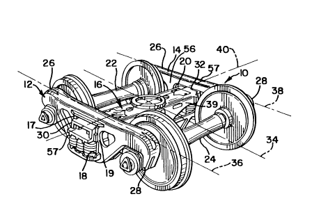
Railcar truck assembly 10 in FIG. 1 is a representative three-piece truck
assembly for a
freight railcar (not shown). Assembly 10 has a first side frame 12, a second
side frame 14 and
bolster 16 extending between generally central openings 18, 20, which openings
18, 20 are
3

CA 02317913 2000-09-07
6166-CIP - Spencer
between forward side frame column 17 and rearward side frame column 19, of the
first and
second side frames 12, 14, respectively. In FIGS. l and 4, railcar truck
assembly longitudinal
axis 34 is generally parallel to side frame longitudinal axes 36, 38. Bolster
longitudinal axis
40 is gcnerally perpendicular to railcar truck longitudinal axis 34 and to
side frame
longitudinal axes 36, 38 at the as-assembled position shown in FIGS. 1 and 4,
corresponding
with a warp reference position. First axle and wheel set 22 and second axle
and wheel set 24
extend between side frames 12, 14 at their opposite forward ends 26 and
rearward ends 28,
respectively. The side frames 12, 14 are generally parallel to each other at
the reference, as-
assembled condition shown in FIGS. 1 and 4. First bolster end 30 is nested in
first side frame
opening 18 and second bolster end 32 is nested in second side frame opening
20.
The connection of bolster 16 in openings 18 and 20 is similarly configured for
either
side frame 12, 14, and the following description will be provided for the
connection of bolster
first end 30 at the first side frame opening 18, but the description will also
be applicable to the
connection of the bolster second end 32 in second side frame opening 20. The
first bolster end
30 has exposed bolster columns 42, 44 between outboard gibs 50, 51 and spaced
inboard gibs
52, 53 on both the forward side 37 and rearward side 39 of the bolster (see
FIGS. 2 and 4-5).
Each bolster column 42, 44 may have friction shoe pockets, shown at 41 and 43
in FIG. 2.
There may be friction shoes 46, 48 in each friction shoe pocket. The bolster
may have a
constant control type of friction shoe or a variable control type of friction
shoe, having a
vertical wearing surface 47, or the bolster columns 42, 44 may comprise a
continuum between
the gibs 50, 52 and between gibs 51, 53, as disclosed in United States Patent
Application
Serial No. 08/850,178 entitled "Improved Bolster Land Arrangement for Railcar
Truck", filed
on May 2, 1997 by V. Terrey Hawthorne, Charles Moehling, Charles P. Spencer
and Terry
L. Pitchford, which is incorporated by reference herein in its entirety. At
each end of the
bolster 16, friction shoe pockets 41, 43 and friction shoes 46, 48 as well as
bolster columns
42, 44 are longitudinally arranged on forward side wall 37 and rearward side
wall 39 of
4

CA 02317913 2000-09-07
6166-CIP - Spencer
bolster 16, respectively. A wear plate 49 may be attached to each side frame
column 17, 19 to
bear against the wearing surfaces 47.
As shown in FIGS. 2-5, the illustrated prior art side frame 12 has an inboard
side 56,
and an outboard side 57. As shown in FIG. 5, each side frame forward column 17
includes an
inboard web 21, an outboard web 23, and a transverse web 25 between the
inboard and
outboard column webs. Each side frame rearward column 19 includes an inboard
web 27, an
outboard web 29 and a transverse web 31 between the inboard and outboard
column webs.
Each side frame opening 18, 20 is between the opposed transverse webs 25; 31
of the columns
17, 19 of the two side frames 12, 14.
As shown in FIGS. 2-5, there is a forward.rotation stop lug 54 on the inboard
side 56
of the forward column 17 of the side frame and a rearward rotation stop lug 55
on the inboard
side 56 of the rearward column 19. The forward rotation stop lug 54 extends
toward the truck
assembly central longitudinal axis 34 from the forward inboard column web 21
and is aligned
opposite the forward inboard bolster gib 52. The rearward rotation stop lug 55
extends toward
the truck assembly central longitudinal axis 34 from the rearward inboard
column web 27 and
is aligned opposite the rearward inboard bolster gib 53. Each rotation stop
lug 54, 55 has a
stop surface 58 spaced from and parallel to a stop surface 60 on the inboard
bolster gibs 52,
53. There is a gap 62 between the opposed stop surfaces 58, 60 of each of the
opposed
rotation stop lugs and the gibs. The gap distance is shown at "a" in FIG. 5,
and may be, for
example, about 3/32 inch, as disclosed in United States Patent No. 3,109,387
(1963) to Carl
E. Tack and entitled "Side Frame-Bolster Interlocking Arrangement for Snubbed
Trucks" .
The gap distance has generally been set in these prior art designs to control
rotation of the
bolster 16 about its longitudinal axis 40. While some freedom of relative
rotation between the
bolster 16 and the side frame 12 and relative to a horizontal plane has been
required to allow
the truck assembly to traverse tracks of varying elevations, the opposed stop
surfaces 58, 60 of
the rotation stop lugs 54, 55 and inboard bolster gibs 52, 53 have restricted
this relative
".
5

CA 02317913 2002-08-30
6166-CIP - Spencer
rotation to a pre-determined range of motion, as described in United States
Patent No.
3,109,387.
Truck warping involves rotation of the bolster 16 about a vertical axis, such
as central
vertical axis 64 in FIGS. 3-4, so that the longitudinal axes 36, 38 of the
side frames 12, 14 and
longitudinal axis 40 of the bolster 16, respectively, are no longer
perpendicular. An example
of such undesirable warping is illustrated in FIG. 3, wherein the angle "a" is
the truck warp
angle, that is, the angle defined by the side frame longitudinal axis 38 with
a reference line 65
that is perpendicular to the bolster longitudinal axis 40; the truck warp
angle "a" is also the
angle defined by the bolster central longitudinal axis 40 with a reference
line 66 that is
perpendicular to the side frame longitudinal axes 36, 38. Thus, the truck warp
angle
corresponds with the angular displacement of the bolster longitudinal axis 40
and the side
frame longitudinal axes 36, 38 from the warp reference position shown in FIG.
4. As
disclosed in United States Patent No. 5,021,186 entitled "'Improved Bolster
Land Arrangement for Railcar Truck", filed on May 2, 1997, truck warping is
problematic: it
can lead to premature wearing of the wheels, and can lead to increased hunting
and poor
curving performance of the truck assemblies.
In the present invention, the problem of truck warping is addressed. Outboard
lugs or
stops 100, 102 are provided on each side frame 12, 14, opposite and aligned
with the bolster
outboard gibs 50, 51, and the gaps 62, 104 are restricted between all of the
aligned inboard
and outboard side frame lugs 54, 55, 100, 102 and the inboard and outboard
bolster gibs 50,
51, 52, 53. With the gaps 62, 104 restricted on both the inboard 56 and
outboard 57 sides,
the permissible range of relative rotation of the bolster 16 about a vertical
axis such as central
vertical axis 64 is restricted. With the range of rotation about vertical axis
64 restricted, the
truck warp angle a may be controlled and minimized.
A first embodiment of a side frame 103 embodying the principles of the present
invention is illustrated in FIGS. 6-8, and such a side frame 103 with a
bolster 16 is shown in
cross-section in FIG. 9. As there shown, like reference numerals have been
used for like parts
6

CA 02317913 2000-09-07
6166-CIP - Spencer
of the side frames and bolster shown in FIGS. 1-4. In the first illustrated
embodiment,
forward and rearward outboard lugs 100, 102 are included on the side frame
103, with a gap
104 between stop surfaces 106 of the side frame outboard lugs 100, 102 and
stop surfaces 108
of the outboard bolster gibs 50, 51. This gap 104 and the gap 62 between the
stop surfaces 58
of the inboard side frame lugs 54, 55 and the opposing stop surfaces 60 of the
inboard bolster
gibs 50, 51 may be substantially restricted to control and limit the truck
warp angle a.
In the first embodiment of the present invention, the forward outboard lug 100
extends
outwardly from the outboard web 23 of the forward side frame column 17. The
rearward
outboard lug 102 extends outwardly from the outboard web 29 of the rearward
side frame
column 19.
At least a part of the stop surface 106 of the forward outboard side frame lug
100 faces
rearward and is generally perpendicular to the side frame longitudinal axis
36. At least a part
of the stop surface 108 of the forward outboard bolster gib 50 is in a facing
relationship with
at least a part of the stop surfaces 106 of the forward outboard side frame
lug 100, and at least
parts of the stop surfaces 106, 108 are in proximity to each other. Together,
the outboard
forward side frame lug 100 and outboard forward bolster gib 50 at one end 30
of the bolster
define an outboard forward neighboring side frame lug and gib, shown in FIGS.
8 and 10. At
least a part of the stop surface 106 of the rearward outboard side frame lug
102 faces forward
and is generally perpendicular to the side frame longitudinal axis 36. At
least a part of the
stop surface 106 of the rearward outboard side frame lug 102 is in a facing
relationship with
the rearward facing stop surface 108 of the rearward outboard bolster gib 51,
and the stop
surfaces 106, 108 are in proximity to each other. Together, the outboard
rearward side frame
lug 102 and outboard rearward bolster gib 51 at one end 30 of the bolster
define an outboard
rearward neighboring side frame lug and gib, shown in FIGS. 8 and 10. On the
inboard side,
at least a part of the stop surface 58 of the inboard forward side frame lug
54 faces rearward
and is generally perpendicular to the side frame longitudinal axis 36. At
least a part of the
.. ..
stop surface 58 of the inboard forward side frame lug 54 is in a facing
relationship with at
7

CA 02317913 2000-09-07
6166-CIP - Spencer
least a part of the stop surface 60 of the inboard forward bolster gib 52.
Together, the inboard
forward side frame lug 54 and inboard forward bolster gib 52 at one end 30 of
the bolster
define an inboard forward neighboring side frame lug and gib, as shown in
FIGS. 8 and 10.
At least a part of the stop surface 58 of the inboard rearward side frame lug
55 faces forward
and is generally perpendicular to the side frame longitudinal axis 36. At
least a part of the
stop surface 58 of the inboard rearward side frame lug 55 is in a facing
relationship with at
least a part of the stop surface 60 of the inboard rearward bolster gib 53.
Together, the
inboard rearward side frame Iug 55 and inboard rearward bolster gib 53 at one
end of the
bolster 30 define an inboard rearward neighboring side frame lug and gib, as
shown in FIGS.
8 and 10. As shown in FIG. 10, both side frames are similarly configured, and
it should be
understood that the above description applies as well to the interface of the
other end 32 of the
bolster in the second side frame 105. In the first illustrated embodiment, the
stop surfaces 108
of the outboard bolster gibs 50, 51 are parallel to the bolster longitudinal
axis 40 and to the
opposing stop surfaces 106 of the side frame outboard lugs 100, 102 when the
three-piece
truck assembly is in the as-assembled condition as shown in FIG. 10.
The magnitude of the gaps 62, 104 between each pair of opposed stop surfaces
106,
108 on the outboard side 57 are shown at "b" and "c" in FIG. 8. The gap
distances "b" and
"c" may each be in the range of about 0.2 to 1/64 (0.015) inches, and each gap
is preferably
less than 3/32 inch and in the range of 3/64 - 1/64 inches. In the first
illustrated
embodiment, the gap distances "b" and "c" are equal in the as-assembled
condition of the
railcar truck assembly, shown in FIG. 10, and the same gap distances "b" and
"c" are used on
both the inboard and outboard sides of the truck assembly. The total of the
gap distance "b"
between at least a part of the stop surfaces 58, 60 of the inboard forward
neighboring side
frame lug and bolster gib 54, 52 and the gap distance "c" between at least a
part of the stop
surfaces 58, 60 of the inboard rearward neighboring side frame lug and bolster
gib 55, 53 in
the illustrated embodiment is the overall clearance or total separation, and
is less than 0.4
inch, and is preferably less than 3/16 inch and in the range between 3/32 and
1/32 inches.
8

CA 02317913 2000-09-07
6166-CIP - Spencer
The total of the gap distance "b" between at least a part of the stop surfaces
106, 108 of the
outboard forward neighboring side frame lug and bolster gib 100, 50 and the
gap distance "c
between at least a part of the stop surfaces 106, 108 of the outboard rearward
neighboring side
frame lug and bolster gib 102, 51 in the illustrated embodiment is the overall
clearance or total
separation, and is less than 0.4 inches, and is preferably less than 3/16 inch
and in the range
between 3/32 a.nd 1/32 inches. Both gap distance totals, b plus c, that is,
both overall
clearances or total separation distances, on both the inboard 56 and outboard
57 sides of the
side frame 103 are the same in the first illustrated embodiment. It should be
understood that
the other side frame 105 of the three-piece truck 107 may be of the same
construction as the
side frame 103 described above, and that the two side frames 103, 105 may be
assembled with
a bolster 16 to form a three-piece truck of the type shown in FIG. 1, except
for the additional
lugs 100, 102 on both side frames and reduced gaps 62, 104. The total gap
distances b plus c,
that is the overall clearance or total separation distance, on the other side
frame and other end
32 of the bolster 16 may also be the same on both the inboard and outboard
sides. It should be
understood that like reference numbers have been used for like parts in the
truck assembly of
FIG. 10 and the prior art truck of FIGS. 1-4, for like parts of the side
frames 103, 105 and the
prior art side frames 12, 14, and for like parts of the bolsters 16.
With the additional outboard side frame lugs 100, 102 of the present
invention, and
with the tight spacing between all of the side frame lugs 54, 55 100, 102 and
opposing bolster
gibs S0, 51, 52, 53, warp angles should be substantially reduced. It may be
possible, for
example, to achieve maximum truck warp angles of less than 2° and
preferably in the range of
about 0.2° to 2°, thereby reducing the potential for damage from
warping and truck hunting.
It should be understood that many variations of the design illustrated in
FIGS. 6-9 may
be employed, and that the present invention encompasses these variations.
Generally, at least
a part of the stop surfaces 58, 60, 106, 108 of each neighboring bolster gib
and side frame
lug, 50 and 100, 51 and 102, 52 and 54, and 53 and 55, are sized, shaped and
spaced so that
at least one of the outboard neighboring bolster gibs and side frame lugs,
such as either the
9

CA 02317913 2002-08-30
6166-CIP - Spencer
combination of gib 50 and lug 100 or the combination of gib 51 and lug 102,
and the
diagonally opposite inboard neighboring bolster gib and side frame lug, such
as either the
combination of gib 53 and lug 55 or the combination of gib 52 and lug 54,
respectively, limit
rotation of the bolster about a vertical axis 64. Thus, the truck warp angle a
may be
controlled, preferably being limited to an angle of about 2°or less and
preferably in the range
of about 0.2° to 2°.
As shown in FIGS. 9-10, the outboard forward and rearward bolster gibs 50, 51
have
outboard limits i 10 and the neighboring outboard forward and rearward side
frame lugs 100,
102 have outboard limits 112. The inboard forward and rearward bolster gibs
52, 53 have
inboard limits 114 and the neighboring inboard forward and rearward side frame
lugs 54, 55
have inboard limits 116. As shown in FIG. 10, in this embodiment, at the warp
reference
position, the distance "d" between the central axis 34 of the truck assembly
and the outboard
limits 112 of the side frame lugs 100, 102 is at least as great as the
distance "e" between the
central axis of the truck assembly and the outboard limits 110 of the outboard
bolster gibs 50,
51. The distance "f " between the central axis 34 of the truck assembly and
the inboard limits
116 of the inboard side frame lugs 54, 55 is no greater than the distance "g"
.between the
central axis 34 and the inboard limits 114 of the inboard bolster gibs 52, 53.
The neighboring
side frame lugs and bolster gibs at the other end 32 of the bolster are
similarly configured.
Alternate shapes may be used for the bolster Bibs and side frame lugs of the
present
invention, such as those disclosed for the land surfaces in U.S. Patent
Application Ser. No.
08/850,178 entitled "Improved Bolster Land Arrangement for Railcar Truck" ,
filed on May 2,
1997 by V. Texrey Hawthorne, Charles Moehling, Charles P. Spencer and Terry L.
Pitchford.
Since it is also desirable that the railcar truck be able to traverse track of
differing
elevations, it will also be desirable to allow a greater range of possible,
relative rotation
between the side frames and the bolster about a horizontal axis 40 than is
allowed about the
vertical axis 64, as disclosed in the application for Canadian Patent Serial
Number 2,317,835
entitled, "Side Frame-Bolster Interface for Railcar Truck Assembly", filed
concurrently herewith
by V. Terrey

CA 02317913 2002-08-30
6166-CIP - Spencer
Hawthorne and bearing docket no. 6178 .
Any of the embodiments disclosed in that patent application can be
applied as well to the inboard and outboard side frame lugs or bolster gibs to
allow a greater
range of rotation about the central longitudinal axis 40 of the bolster than
about the central
vertical axis 64 of the bolster. In effect, the side frame lugs or bolster
Bibs or both may be
shaped so that part of the contact surfaces control the warp angle and part
controls pitch angle.
Thus, one or both of the cantact surfaces of each neighboring side frame lug
and bolster gib
may comprise a warp control surface and a pitch control surface. The gap
distances "b" and
"c" between the warp control surfaces may each be less than 3/32 inch and in
the preferred
range of 3/64 - 1/64 inches while the gap distance between the pitch control
surfaces may be at
greater distances. Thus, at a gap of 1/64 inch between the warp control
surfaces, the opposing
warp control surfaces of the side frame lugs and bolster gibs may limit the
truck warp angle to
0.22°, or about 0.2°, and gaps in the range of 1/64 - 3/64
inches may limit the truck warp
angles to the range of about 0.2° - 2°, while the opposing pitch
control surfaces of the side
frame lugs and bolster gibs allow a greater range of pitch angles. Examples of
such shapes are
illustrated in FIGS. l I-14, but it should be understood that any shape
disclosed in that patent
application may be used at any of the side frame lugs and bolster gibs. It
should also be
understood that any of the shapes disclosed in that application may be
combined with any of
the shapes disclosed in U.S. Patent rsc . 5, 9 21,18 ~ .
As shown in FIG. 11 of the present application, the side frames 203 may have
inboard
lugs 254, 255 and outboard lugs 200, 202 with stop surfaces 258, 206 that each
include a warp
control surface 270 and a relief surface 271 for pitch control. The gibs of
the bolster (not
shown) may have stop surfaces that are flat and vertical, so that the entire
gib stop surface
comprises a warp control surface and a pitch control surface, or the stop
surfaces could also
include warp and pitch control surfaces such as shown in FIGS. 13-14. As shown
in the
embodiment of FIG. 12, the side frame 303 inboard lugs 354, 355 and outboard
lugs 300, 302
' ~ may have stop surfaces 358, 306 that comprise curved surfaces, with
outermost points 370
11

CA 02317913 2000-09-07
6166-CIP - Spencer
comprising warp control surfaces and the remainder of the stop surfaces
comprising relief
surfaces 371 that curve away from the side frame central transverse axis 340
to allow the
bolster (not shown) to pitch within a predetermined range of angles.
As shown in FIG. 13 of the present application, the bolster 516 may have
inboard gibs
553 and outboard gibs 561 with stop surfaces 560, 508 that each include a warp
control
surface 570 and a relief surface 571 for pitch control. The lugs 500, 554 of
the side frame
503 may have stop surfaces 558, 506 that are flat and vertical, as in the
embodiment of FIGS.
6-9, so that the entire stop surface 558, 506 comprises both a warp control
surface and a pitch
control surface, or the stop surfaces could also include both warp control
surfaces and relief
surfaces such as shown in FIG. 12. In any of the embodiments of FIGS. 11-14,.
each pair of
opposing warp control surfaces may be spaced at a distance less than 3/32 inch
and preferably
in the range of 3/64 - 1/64 inches, with the relief surfaces spaced at a
greater distance to allow
the bolster 516 or 616 to have a range of pitch angles greater than the warp
angle. Limiting
the total separation or overall clearance to a distance less than 0.4 inch and
preferably less than
3/32 inch and closer to 1/32 inch limits the truck warp angle to an angle
between about
0.2°and 2.0° while the larger gap between the side frame contact
surface and the relief or pitch
control surface of the bolster gibs may allow a greater maximum pitch angle
of, for example,
1.0°, 2.0°, or some other angle, depending on the depth of the
relief provided. As shown in
the embodiment of FIG. 14, the inboard gibs 653 and outboard gibs 651 of the
bolster 616
may have stop surfaces 608, 660 that comprise curved surfaces, with the
outermost points 609,
661 comprising warp control surfaces and the remainder of the stop surfaces
comprising relief
surfaces that curve toward the.bolster longitudinal centerline 640 to allow
the bolster 616 to
pitch within a predetermined range of angles.
In addition, as shown in the embodiment of FIG. 17, the present invention may
also be
used with side frames 403 and bolsters 416 of the wide land type. In prior art
wide land side
frames, there have been no side frame lugs. In the present invention, both
inboard side frame
lugs such as lug 454 and outboard side frame lugs such as lug 400 may be used
along with
12

CA 02317913 2000-09-07
6166-CIP - Spencer
bolsters 416 having inboard gibs and outboard gibs such as inboard gib 452 and
outboard gib
450 of the FIG. 17 embodiment. In this embodiment, the gap distance "b" and
the gap
distance "c" (not shown) would again be used to control or limit the warp
angle. It should be
understood that any of the above-described shapes of lugs and gibs may be used
with the wide
land type of side frame.
,.
The side frame and bolster of the present invention may be made as a steel
casting with the
additional outboard lugs and gibs cast as parts of the side frame and bolster.
To achieve the
gaps distances "b" and "c", it should be understood that the dimensions of the
side frame lugs
or bolster gibs or both may be set to provide the desired gaps, with the lugs
and gibs being
cast with or machined to the desired dimensions. Alternatively, side frames
and bolsters could
be cast with the lugs and gibs at greater than the desired gap distance and
then modified to
provide the desired gap distances, or standard side frames and bolsters could
be modified to
provide the desired gap distances, by providing separate plates or other
structures to be
attached to either the side frames or bolsters or both of them. The gap
reductions could be
achieved through the addition of wear plates or the like to the lugs or gibs
so that
manufacturing tolerances for the side frames and bolsters can be greater. For
these purposes,
the wear plates could be made of a hardened material, for example, or could
comprise a
resilient material that compresses a pre-determined amount. The wear plates or
resilient
material could be shaped, for example, like the wear members 700, 701
illustrated in FIGS.
15 and 16, with attachment surfaces 702, 703 for attachment to the side frame
or bolster
adjacent or opposite to the stop surfaces 704, 705. As shown in FIG. 16, the
wear member
701 may be shaped to provide a warp control surface 707 and relief surfaces
709. If a
resilient material is used, the resilient material could be placed between the
opposing contact
surfaces of the side frame lugs and the bolster gibs, in contact with both
opposing stop
surfaces of each pair; in such an embodiment, the gap distance "b: or "c"
could comprise the
thickness of the resilient material in the as-assembled truck assembly such as
that shown in
FIG. 10. The means of attaching such a wear plate or resilient material to the
side frame or
13

CA 02317913 2000-09-07
6166-CIP - Spencer
bolster should be understood to vary with the material used; a steel wear
plate could be welded
to the desired part of the side frame or bolster, and either type of material
could be attached by
nuts and bolts, screws, adhesive, or any other desirable means. Use of
structures such as
those shown in FIGS. 15 and 16 may be advantageous in that it may be
relatively easy to
replace the structures if they become worn through use. It should be
understood that other
materials could be used as well, and the present invention is not limited to
any particular
material or method of manufacture.
While specific gap distances and truck warp angles have been set forth herein,
it should
be understood that the distances and angles have been given for purposes of
illustration only.
The present invention is not limited to any particular gap distance or warp
angle unless
expressly set forth in one of the claims. It should also be understood that
from the disclosure
in this application, once a desired range of warp angles has been determined,
the necessary
gap may be determined from the dimensions and geometry of the particular side
frames and
bolster used in the railcar truck assembly.
In the several embodiments of the above-noted side-frame lugs and bolster
gibs, the
above portions described as at least part of the stop surfaces in proximity to
each other are
hardened to a specific hardness. More specifically, in the embodiment of
Figures 6 to 8 either
stop surface 106 or 108 may be flame hardened to a hardness between about 375
BHN to 515
BHN to a depth below the stop surface of about twelve hundredths inch. The
entire length of
the illustrated bolster gib surface 108 and side frame lug surface 106 is not
required to be
hardened beyond the as-cast hardness, which is typically in the range of 137
BHN to 208
BHN, but rather those parts of the surface in close proximity to each other at
assembly or
which are most often in contact during operation of the railcar truck
assembly. This hardening
of the proximate surfaces is applicable to all of the inboard and outboard
side frame lug stop
surfaces 106 and bolster gib stop surfaces 108.
In the embodiment of Figure 11, outboard lugs are shown with stop surfaces 258
and
"°' 206, which include warp-control surface 270 and relief surface 271
for pitch control. In this
14

CA 02317913 2000-09-07
6166-CIP - Spencer
embodiment, warp-control surfaces 270 of inboard lugs 254, 255 and outboard
lugs 200, 202
may be flame hardened to elevate the hardness levels of these surfaces to a
range of 375 BHN
to 515 BHN from the typical as-cast range of 137 BHN to 208 BHN. Although the
pitch
control relief surfaces 271 can be hardened, it is not a requisite to harden
them and the
reduced hardness levels provide for potentially greater flexural toughness and
fatigue
resistance. Figure 12 illustrates inboard side-frame lugs 354, 355 and
outboard side-frame
lugs 300,302 having stop surfaces 358, 306 with curved surfaces, which curved
surfaces have
outermost points 370 as warp control surfaces and the remainder of surfaces
358 and 306 are
provided as relief surfaces. Again, it is only necessary to flame harden warp
control surfaces
370 to a range of 375 BHN to 515 BHN and preferably to a depth of about twelve
hundredths
inch to provide improved wear characteristics.
Bolster 516 in the embodiment noted in Figure 13 has inboard gibs 553 and
outboard
gibs 561 with respective stop surfaces 560, 508 having warp control surfaces
570 and relief
surface 571. As noted above, side-frame lugs 500, 554 may have respective lug
stop surfaces
558, 506 that are flat and vertical, such that entire stop surface 558, 506
provides both a warp
control surface and a pitch control surface. Alternatively, the stop surfaces
could include both
warp control surfaces and relief surfaces, as noted in Figure 12.
In the embodiment of Figure 14, inboard gibs 653 and outboard Bibs 651 of
bolster 616
are illustrated with curved stop surfaces 608,660. The warp control surfaces
for stop surfaces
608,660 have respective outermost points 609,661 with the balance of the stop
surfaces
operable as relief surfaces. In this embodiment, curved stop surfaces at
points 609, 661 may
be hardened to the preferred hardness range of 375 BHN to 515 BHN, which
hardness may
extend into bolster gibs 653 and 651 to a depth of about twelve hundredths
inch. Again, the
entire arcuate or curve surface of stop surfaces 608 and 660 are not required
to be hardened.
In a preferred condition, the midpoint of the vertical height of stop surfaces
608 and 660 may
be considered, and the points 609, 661 would preferably be hardened over
approximately one
. :;.,
,:
"" sixth of the vertical height on either side of such midpoint. This range of
coverage is

CA 02317913 2000-09-07
6166-CIP - Spencer
generally characterized in Figure 14 by the position of outermost point 661
and its associated
lead line directed to the approximate vertical midpoint and the shading lines
on surface 660
provided on either side of such midpoint as an illustration of the range of
surface to be
hardened. It is to be noted that this is merely an illustration and not a
limitation.
The embodiment of Figure 17 illustrates an improvement of the wide-land side-
frame
structure and incorporates both inboard side-frame lugs 454 and outboard side-
frame lugs 400.
The side-frame lugs 454 and 400, as well as the bolster inboard gibs 452 and
outboard gibs
450 may be hardened to the desired hardness range of 375 BHN to 515 BHN at
their
outermost or contact points.
In Figures 15 and 16 and as-described above, wear plates or resilient material
could be
shaped as wear members 700 and 701 with attachment surfaces 702 and 703 fvr
attachment to
the respective side-frame and bolster adjacent or opposite stop surfaces 704,
705. At least the
central region or approximate center one-third of stop-surface 705, or wear-
control surface
707 in Figure 16, would again be provided with the increased hardness element
or it could be
hardened by the below-noted hardening techniques. Similarly, stop-surface 704
could be
hardened in the anticipated contact area by the addition of a wear plate, wear-
plate insert or by
the below-noted hardening techniques.
The alternative embodiments noted above have indicated that the specific
contacting
surface may be hardened, however, it is recognized that both the bolster gib
stop-surface and
the side-frame lug contacting stop surfaces may be hardened to extend their
respective wear
rates. The desirability of hardening the full length of the gibs or lugs may
be dependent upon
the contact area between the facing surfaces of the respective components. It
is desirable to
harden only the localized region, but it is recognized that the entire stop
surfaces of the
respective lugs or gibs may be hardened. Further, although it has been noted
that a flame
hardening technique may be utilized, it is recognized that the stop-surface
contact points, or
..:~., the entire lengths of the stop surfaces could be hardened by
alternative means such as
16

CA 02317913 2000-09-07
6166-CIP - Spencer
induction hardening or by a hard coating process like flame-spraying. The
latter condition
must accommodate any dimensional change. from a build-up of material.
While only specific embodiments of the invention have been described and
shown, it is
apparent that various alterations and modifications can be made therein. It
is, therefore, the
intention in the appended claims to cover all such modifications and
alterations as may fall
within the scope and spirit of the invention. Moreover, the invention is
intended to include
equivalent structures as well as structural equivalents to those described
herein.
>.,,.,,::,,
17

Representative Drawing
A single figure which represents the drawing illustrating the invention.
Administrative Status

For a clearer understanding of the status of the application/patent presented on this page, the site Disclaimer , as well as the definitions for Patent , Administrative Status , Maintenance Fee  and Payment History  should be consulted.

Administrative Status

Title Date
Forecasted Issue Date 2003-06-03
(22) Filed 2000-09-07
Examination Requested 2000-09-07
(41) Open to Public Inspection 2001-03-16
(45) Issued 2003-06-03
Deemed Expired 2005-09-07

Abandonment History

There is no abandonment history.

Payment History

Fee Type Anniversary Year Due Date Amount Paid Paid Date
Request for Examination $400.00 2000-09-07
Registration of a document - section 124 $100.00 2000-09-07
Application Fee $300.00 2000-09-07
Maintenance Fee - Application - New Act 2 2002-09-09 $100.00 2002-07-12
Final Fee $300.00 2003-03-21
Maintenance Fee - Patent - New Act 3 2003-09-08 $100.00 2003-09-03
Owners on Record

Note: Records showing the ownership history in alphabetical order.

Current Owners on Record
AMSTED INDUSTRIES INCORPORATED
Past Owners on Record
SPENCER, CHARLES P.
Past Owners that do not appear in the "Owners on Record" listing will appear in other documentation within the application.
Documents

To view selected files, please enter reCAPTCHA code :


To view images, click a link in the Document Description column. To download the documents, select one or more checkboxes in the first column and then click the "Download Selected in PDF format (Zip Archive)" or the "Download Selected as Single PDF" button.

List of published and non-published patent-specific documents on the CPD .

If you have any difficulty accessing content, you can call the Client Service Centre at 1-866-997-1936 or send them an e-mail at CIPO Client Service Centre.


Document
Description 
Date
(yyyy-mm-dd) 
Number of pages   Size of Image (KB) 
Description 2002-08-30 17 968
Cover Page 2003-04-30 1 57
Cover Page 2001-02-28 1 56
Abstract 2000-09-07 1 28
Description 2000-09-07 17 945
Claims 2000-09-07 19 943
Drawings 2000-09-07 10 274
Representative Drawing 2001-02-28 1 23
Correspondence 2003-03-21 1 29
Correspondence 2003-09-19 1 14
Assignment 2000-09-07 5 195
Prosecution-Amendment 2002-07-17 2 41
Prosecution-Amendment 2002-08-30 6 322
Correspondence 2010-06-10 8 327
Correspondence 2010-06-22 1 15