Note: Descriptions are shown in the official language in which they were submitted.
WO 99/37470 PCT/US99101644
-1-
RETROREFLECTIVE MATERIAL HAVING PRINTED PATTERNS THEREON
BACKGROUND OF THE INVENTION
A demand exists for retroreflective materials
having printed patterns or graphics formed thereon.
Retroreflective material is capable of reflecting the
predominant portion of light rays impinging thereon in a
substantially parallel path toward the source of the
light. A particularly efficient type of retroreflective
element employs molded members of cube-corner
formations. Cube-corner :reflectors molded from glass
and more recently from acrylic resins or oligomers have
commonly been employed as safety devices on bicycles,
automobiles and other vehicles.
U.S. Patent 3,689,346 describes a process in which
retroreflective sheeting is produced on a continuous
basis by applying transparent sheet material over a
hardenable molding material previously deposited upon a
moving mold surface, after which the molding material is
solidified and bonded to the sheet material to produce a
composite structure. The mold surface has an array of
minute, contiguous cube-corner recesses therein, so that
the sheeting correspondingly has a multiplicity of
closely spaced cube-corner formations spaced about and
projecting from a smooth surface of the sheet material,
which provides the body portion thereof.
U.S. Patent 5,643,400 describes a continuous
process for making lengthy sheets of "seamless
retroreflective sheeting using mold surfaces formed on a
pair of rotatable drums.
U.S. Patent 4,082,426 discloses a method of
introducing markings into retroreflective sheeting which
are visible when the sheeting is viewed at an angle
CA 02318039 2000-07-12 SUBSTlTUTE SHEET (RULE 26)
WO 99/37470 PCTIUS99/01644
-2-
are visible when the sheeting is viewed at an angle
under retroreflective viewing conditions to enable a
viewer to determine the identity of the sheeting. The
markings are provided on a transparent image layer
disposed between a spacing layer and a specularly
reflective layer. U.S. Patent 2,354,049 discloses a
stop sign having embossed (raised) lettering upon which
a separate sheet of reflex.light-reflector
(retroreflector) material is applied to provide improved
sight visibility. The beaded or retroreflective areas
of the sheet are covered with black ink or paint in the
raised letter areas to make the letters stand out more
plainly.
U.S. Patent 2,231,139 discloses a sign structure in
which the sign character is formed of protuberances
formed integral with a translucent plate to produce
reflection of incident light.
U.S. Patent 2,422,256 discloses a decalcomania
transfer of retroreflective elements in which the sign
design is pasted upon a decal base and coated with
reflex-reflecting elements.
U.S. Patent 4,656,072 produced colored indicia in
retroreflective articles by patterns produced using
colored adhesives which ax=e visible behind
retroreflective material.
U.S. Patent 4,952,023 discloses an internally
illuminated sign in which a graphic on a transparent
face sign is made visible from the front of the sign by
retroreflected light, internal illumination or both.
Despite the many efforts by those skilled in the
art, and the above represents only a small sampling,
there still remains an unf:ulfilled need for a high
speed, high quality, low cost process of producing
printed patterns for graphic, decorative and other
utilitarian purposes on retroreflective sheeting.
SUBSTtTUTE SHEET (RULE 261
CA 02318039 2000-07-12
WO 99/37470 PCT/US99/01644
-3-
SUMMARY OF THE INVENTION
In accordance with the invention, partially
solidified printed patterr.is or graphics are formed on a
transparent film utilizing a rotary screen printer. The
film is then fed to prism forming station(s) where
partially solidified transparent microprism structures
are bonded over the printed patterns. The patterns and
prisms are solidified and merged together thereby
providing a long lasting image which is protected from
the environment by being incorporated into the prism
structure and covered by the film.
The prism structures may be designed to be
retroreflective and have an air interface or reflective
coating backing to the prism facets. The printed
patterns can be used to erihance certain properties of
the product such as whiteriess. This can be accomplished
by printing the pattern on a continuous roll or web of
film around a drum and curing the prisms and patterns in
line with other processes on the same or additional
drums.
It is also possible to screen print onto a nickel
tool one variety of prism forming liquid resin, and also
screen print onto a web or film a different resin, and
to then laminate the web to the tool. The material is
then UV cured and stripped from the tool. What has been
formed is a product with ciifferent characteristics
between the top and bottom of the microstructure. This
can be used to assist in _}oining the formed product to
other substrates, or it can provide optical qualities to
the film caused by the variance in physical properties
in the microstructure. Physical properties that can be
varied include color and refractive index.
Another use of the rotary screen printing method is
to print patterns which enhance certain properties of a
product, such as CAP Y or whiteness. In this method,
lines or dots in a pattern, either repeating or random,
SUBSTI7'UTE SHEET (RULE 26)
CA 02318039 2000-07-12
CA 02318039 2007-03-23
-4-
can be printed and cured onto a moving web in line with
other processes, such as the casting of microstructures.
The printed lines or dots are under the top surface of
the film, and above the microstructures and hence
protected on both the top and the bottom. Either
transparent or opaque inks can be used. In the case of
opaque inks, they will show their color during daytime,
but at night their pattern will appear black under
reflected light from a microprism product. A colored
transparent ink will reflect its color both in daytime
and under reflected light.
Other transparent or opaque features can be printed
in-line before a casting process, such as customized
logos, colored stripes, specification markings or any
number of identifying features. These items could be
printed on a variety of microstructures, including
microprisms, holograms, lenticular arrays, etc. All
screen printed features can be printed in register with
either a microstructure pattern or to another print
pattern. This can provide for the masking of undesirable
features, such as seamlines, or it can be used to add
decoration to a product. Note that several screen
printing heads can be used in sequence to achieve
features with multiple colors or layers.
In a general aspect of the general invention, there
is provided that an apparatus has coater for producing
visible patterns on a transparent film, and prism forming
apparatus. The apparatus is for applying transparent
microprisms onto the pattern, such that the patterns are
viewable and protected from the environment by being
incorporated into the microprisms and covered by the
film. The microprisms have a base and side facets. The
patterns and microprisms are partly solidified as formed.
After the microprisms are applied to the patterns, the
CA 02318039 2007-03-23
- 4a-
patterns and microprisms are solidified so that the
printed patterns are embedded into the base of the
microprisms.
BRIEF DESCRIPTION OF THE DRAWINGS
Figure 1 is a schematic illustration of apparatus
embodying the method of the invention.
Figure 2A is a view taken along the lines I-I of
Figure 2B of a portion of a web of film during step 1 of
the method of the invention.
Figure 2B is a side view of a portion of a web of
film during step 1 of the method of the invention.
Figure 3B is a view taken along lines II-II of
Figure 3B of a portion of a web of film during step 2 of
the method of the invention.
WO 99/37470 PCT/US99/01644
-5-
Figure 3B is a side view of a portion of a web of
film during step 2 of the method of the invention.
Figure 4A is a view taken along lines III-III of
Figure 4B of a portion of a web of film during step 3 of
the method of the invention.
Figure 4B is a side view of a portion of a web of
film during step 3 of the method of the invention.
Figure 5 is a fragmentary sectional view at a
location about the drum axis illustrating the deposit of
liquid from a coating head onto the printed matter on
the web of film.
Figure 6 is a fragmentary sectional view of the
partially finished sheeting to an enlarged scale.
Figure 7 is a view of' a portion of a continuous
sheet of material made in accordance with the invention.
Figure 8 is a fragmentary sectional as in Figure 6
showing an alternate embodiment of the invention.
Figure 9 is a section as in Figure 8 showing a
further step in the process.
Figure 10 is a schematic illustration of an
apparatus of the method of: the present invention.
Figure 11 is a side view of a portion of an
embodiment of a retroreflective structure formed by a
method of the invention.
Figure 12 is a side view of a portion of a second
embodiment of a retroreflective structure formed by a
method of the invention.
Figure 13 is a side view of a portion of a third
embodiment of a retroreflective structure formed by a
method of the invention.
Figure 14 is a side view of a portion of a fourth
embodiment of a retroreflective structure formed by a
method of the invention.
Figure 15 is a side view of a portion of a fifth
embodiment of a retroreflective structure formed by a
method of the invention.
SUBSTITUTE SHEET (RULE 266~
CA 02318039 2000-07-12
WO 99/37470 PCT/US99/01644
-6-
Figure 16 is a side view of a portion of a sixth
embodiment of a retroreflective structure formed by a
method of the invention.
Figure 17 is a side view of a portion of a seventh
embodiment of a retroreflective structure formed by a
method of the invention.
Figure 18 is a top view of the structure in Figure
17.
Figure 19 is a top view of an embodiment similar to
Figure 18 but with a document printed upon it.
Figure 20 is a side view of a portion of an eighth
embodiment of a retroreflective structure formed by a
method of the invention.
Figure 21 is a side view of a portion of a ninth
embodiment of a retroreflective structure formed by a
method of the invention.
The foregoing and other objects, features and
advantages of the invention will be apparent from the
following more particular description of preferred
embodiments of the invention, as illustrated in the
accompanying drawings in which like reference characters
refer to the same parts throughout the different views.
The drawings are not necessarily to scale, emphasis
instead being placed upon illustrating the principles of
the invention.
DETAILED DESCRIPTION OF THE INVENTION
The apparatus of the invention includes a well-
known rotary screen printer 10 of the type made by Stork
X-Cel B.V., The Netherlands. The printer is positioned
at a print station A and is comprised of an upper plate
cylinder 10A and a lower impression cylinder lOB. A web
of film 46, to be printed upon, is unwound from the
unwind station 42 and fed. between an opening or nip 48
between the cylinders 10A. and lOB, such that a pattern
20 of any design can be imprinted on the film 46. A
SUBSTiTUTE SHEET (RULE 26)
CA 02318039 2000-07-12
WO 99/37470 PCT/US99/01644
-7-
squeegee (not shown) in cylinder 10A expresses or
squeezes a paste of ink, paint, resin, colored oligomers
or other print liquids through engraved or etched
openings in a wire or nickel screen (not shown) provided
on plate cylinder 10A. The uncured patterned film 46B
is then fed to a laminating roller 50 where it is bonded
to an array of partially solidified, transparent cube-
corner prisms 64 formed in rotary molds 23 disposed
around the circumference :L4 of drum A.
A coating assembly, generally designated by the
numeral 24 is mounted adjacent a segment of a drum A.
This assembly consists of three coating stations: 241,
242 and 243, each one of which applies a metered amount
of prism forming clear liquid, i.e., resin into the
prism recesses (not shown) in molds 23. Each station
includes the appropriate controls and rollers to
precisely deposit the liquid without overfilling the
recesses. Note, however in some applications it may be
desirable to leave air bubbles in the prisms as
described in U.S. Patent 5,592,330. The three stations
are used to enhance the removal of air from the bottoms
of the prismatic recesses.
A bank of ultraviolet lights 40 is mounted adjacent
the drum A for curing or solidifying of the materials
deposited thereon at a point about the axis between the
laminating roller 50 and a cold air plenum 38.
A stripping roll 52 is disposed on the opposite
side of the drum A, and the printed formed sheeting
generally designated by the numeral 54 passes about it
in its travel to either rewind roll 441 (shown in dotted
lines) or to an optional second screen print station B
and second prisms forming station B. Note that the
second print station B and forming station B is not
required if the entire circumference of the molds in
drive A is initially filled with optical structures to
make a continuous web of sheeting.
SUBSTI'IUTE SHEET (RULE 26)
CA 02318039 2000-07-12
CA 02318039 2006-08-22
-8-
Before proceeding further, a brief review in
connection with the generalized schematic flow diagram of
the preceding main process steps up to the point of
stripping off the laminated product may be in order.
This review will be described in connection with Figures
2A-23.
In step 1, Figures 2A and 2B, a transparent or clear
web of film 46 is fed into the rotary screen printer 10
of Figure 1 where a partially cured oligomer pattern 20,
such as the letters BI, is printed on the clear film, as
shown in Figures 3A and 3B.
Alternatively, the pattern may be a series of
diagonal lines across the entire film formed, for example
by a colored oligomer, such as an oligomer with a
titanium oxide(Ti02) pigment to create a white pattern
which serves to improve the CAP Y or whiteness of the
finished sheeting. Also the pattern can be disposed at
areas where the mold plates 23 meet, so as to cover the
seams formed in the casting operation.
Next, as shown in Figures 4A-4B, transparent, clear
or colored oligomer prisms 64 are cast upon the partially
cured colored printed pattern 20. During the time that
the film 46B passes through the laminating roll 50, the
roll pressure causes the partially cured printed pattern
20 to be pushed into the prism mold cavities 21 (Figure
5) causing the completely cured product 54 (Figure 6) to
be formed of completely clear prisms 64A and some prisms
64B with a colored pattern 20 between and within the
prisms and the film 46B such that the pattern 20 can be
viewed from the exposed side indicated by the light rays
R in Figure 6.
The apparatus of the invention can also be used to
mix and match various prism sizes and materials on an
integral retroreflective sheet by feeding a modified
version of the sheeting produced at prism forming station
A to a further prism forming station B. In this
WO 99/37470 PCT/US99/01644
-9-
embodiment, the drums A and B are each provided with a
number of prism molds 23 or tools with prism-shaped
recesses 21 therein which can be filled with suitable
oligomers, or resins.
The molds 23' in drum B can produce microprisms of
a different pitch or size, and/or different orientation
or tilt from the molds 23 in casting drum A. Also, as
previously described, the rotary screen printer 10 can
be used to register and print on the clear film 46 well
defined areas or patterns of oligomers 20 on the film
46B which are then transferred to the prisms formed in
the first molds 23 during the curing process performed
by UV lights 40.
The same printing concepts can be used to register
and print suitable prism forming oligomer in the
recesses of a second set of tools 23' on drum B using
the second rotary screen printer 12 at station B.
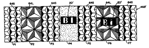
Figure 7 illustrates some of the many variations in
prism size, texturing and graphics that can be
introduced into retroreflective sheeting 54 using the
apparatus of Figure 1.
Figure 7 depicts a top-view of a portion of a sheet
of retroreflective material in which alternate portions
P1-P7 are fabricated on alternate drums A and B. For
example, portions P1, P3, P5 and P7 are formed on Drum A
using small prism pitch tooling 23 to form small size
prisms 64S without graphics supplied from print station
A, and portions of the tooling at P2, P4, P6 left blank
until the film 46B' is fed into drum B at prism forming
station B.
The tooling 23' on drum B forms larger size prisms
in the portions P2 and P6, whereas the tooling on drum B
creates textured surfaces on the film or sheeting 46B'
at portions P4.
The print station B can be operated to provide
graphics for the film 46B' at any portion such as P4 or
CA 02318039 2 0 0 0- 07-12 SUBSYffl11E SHEET (RULE 26)
WO 99/37470 PCT/US99/01644
-10-
P6 prior to formation of texture as in P4 or bonding of
prisms, as in P6.
It should be noted that the patterns, such as the
graphic BI of 20' can be of any shape or size depending
upon the desired pattern or optical properties required.
Also, the portions between the first (A drum) tooling
and second (B drum) tooling can be left void of oligomer
to increase the Cap Y or whiteness of the product.
Turning now to Figure 8, an alternate embodiment of
the invention is illustrated therein in which a release
coating or layer 99 is formed on the film 46B prior to
printing the printed matter 20 on the film and prior to
bonding the partially cured microprisms 64A over the
printed matter 20. After the facet sides of the prisms
64A are made reflective, such as by metallizing with
suitable material 98, the structure can then be applied
to a suitable substrate 96 using an adhesive 97 to bond
the metallized prism side to the substrate 96. Next,
the film 46B and release layer 99 can be removed leaving
the window or base side 61 of the prism array exposed
along with the printed matter 20. At this point a
suitable transparent protective layer 95 can be formed
thereover as shown in Figure 9.
This embodiment is particularly useful for
providing fluorescent signage where the paint material
20 can be made of fluorescent material in the order of
12.7 to 76.2 micrometers (0.0005 to 0.003 inches) thick
and the protective layer 95 on substrate 96 can be also
made of a thick fluorescent material, in the order of
152.4 to 254 micrometers (0.006 to 0.01 inches).
Material such as acrylic, vinyl, or polycarbonate,
selected according to its durability rather than its
adaptability to an on-line rotary film process of
manufacture can also be used for the protective layer.
The concept of leaving some areas of web or film 46
without oligomer can also be used to create an easy seal
CA 02318039 2000-07-12 SUBSTnUM SHEET (RULE 26)
WO 99/37470 PCTIUS99/01644
-1:L-
material. Retroreflective:, ultrasonic or heat sealing
becomes much easier if the very hard thermoset oligomer
prisms do not need to be forced out of the way to allow
a thermoplastic top film t:o flow and bond to a
thermoplastic backing film. The pressure of contact
plus the heat directed by the various sealing techniques
will create a strong, homogeneous bond between the top
film and backing film giv:ing a very durable final
product.
In addition, a web or film which is previously
printed with a pattern such as a white dot or crosshatch
pattern can be processed through the two casting drums A
and B, and the discrete areas of oligomer can be
registered to fill in the non-white areas with
retroreflecting corner cube prisms of the size and
orientation and tilt desired.
Finally, it is proposed that a web or film 46 which
is previously embossed or cast with a pattern of
microstructures, such as lenslets or grooves or linear
prism structures, can be additionally processed using
the two casting drums A and B as described above. The
discrete areas of oligomer cured corner cubes on the
drums A and B can be separated to bond onto the
previously cast or embossed microstructures. The cast
or embossed microstructures can be located in discrete
locations or in patterns of varying microstructures to
enhance the overall performance of the retroreflective
film produced.
It should now be obvious that this invention can be
extended to more than two casting drums and also to the
manufacture of unique free prism systems.
Further details of the station B process will now
be described with the aid of Figure 1. Sheeting 54
travels from optional print station B, and printer 12
and cylinders 70A and 70B to the second drum B where it
proceeds through a set of devices similar to that
CA 02318039 2000-07-12 SUBSTIME SMEET (RULE 26)
16-02-2000 9/ 016 4 4 U S 009901644
4 ,
= i == == == ~~ =i
11 a= ~1 ~ = = = = = s ~ =
'= _f = ! === ~ = = = = = = = =
~ = ~ = = = = = = s =
isv =0 == ==== t-i el
_ 1 2 -
described in connection with drum A. The similar
devices are designated by a prime suffix. Edge trimming
stations 80' and 80 are employed after each station to
remove any poorly replicated edges from the web 54. The
motors 56 and 56' drive the drums A and B respectively
in a conventional manner, under computer control from
control system 100 using coupling chains 58 and 58'
provided about the shafts 11 and 11' and shafts 60 and
60'.
Synchronized operation of the apparatus will be
apparent from the foregoing and the following
description. As the drums A and B and cylinders 10A,
lOB, 70A and 70B continuously rotate, hardenable
printing/molding material in fluid form is deposited
thereupon on the prismatic recesses of molds 23 and 23'
and on the film 46/54. The coating stations 24/24' and
print stations A and B are held in register through the
homing sensors 82/82' mounted adjacent the circumference
of the cylinders 10 A/B 70 A/B and drums A, B in a fixed
position. The homing sensors provide an electrical
feedback signal to the control system 100 to adjust the
position of the coating stations 24/24' and paint
stations. Film 46 is continuously withdrawn from the
feed reel 42 and applied first against the print station
A and then drum A by the laminating roll 50, which
cooperates with the drum A to provide a nip at which the
hardenable material 64 is uniformly distributed,over the
surface of the prism array recess areas 21 of the
selected molds 23 on drum A, and at which intimate
contact is effected between the prism material 64 and
the unsolidified pattern 20 on printed film 46B.
The freshly applied material 64 and the film 46
with the freshly applied printed matter 20, travel
together past the bank of ultraviolet lamps 40, where
-35 hardening of the materials 64 and 20 and bonding thereof
CA 02318039 2000-07-12 AMENDED SHEET
WO 99/37470 PCT/US99/01644
-1.3-
to the film 46B are concurrently effected. Thereafter,
the cold air plenum 30 helps the material cool so that
the partially completed reflective sheeting 54 can be
readily stripped from the drum A.
The partially completed film 54 is optionally fed
through print station B where additional printed matter
20' can be printed on the film. First, the film
traverses past a registration check optical sensor 90.
This sensor feeds an electrical signal related to the
position of printed matte:r and prisms on the incoming
web 54 to the computer control system 100 and positional
corrections are processed to ensure that the partially
completed reflective film 54 is in proper alignment to
contact print station B and the drum B. After printing
more matter 20' on web 54, the web is fed through the
laminating roll 50', where it encounters the next
freshly applied hardenable prism material 64' on the
prism array recess areas of the molds 23' on drum B, but
only at the spaces left empty on the film in the
previous operation.
The timing of this operation should be done with
precision, such that the two drives A and B operate in
synchronization to preferably either eliminate any seam
forming when the second operation is performed or to
overlap the seams. Preferably, the two stations A and B
are synchronized by a Berkeley Process Control System,
Series 64, manufactured and sold by Berkeley Process
Control, Inc. (labeled control system 100 in Figure 1).
The first curing and print stations A are used as
the master axis, and the second stations B are
controlled to register the second station in line and to
wind up the material. Precise machine control over all
the drive mechanisms coupled with optical encoder
feedback and a dedicated input utilizing flying position
measurement is suggested.
SUBSTITUTE SHEET (RULE 26)
CA 02318039 2000-07-12
16-02-2000 9/01644 US 009901644
= = ~ ~= == == ~i !i
=1 i= ~~ = = ~ ~ ~ = ! ! =
7 ~ 1 i ==~ ~ ~ = = = = ~ ! =
~ a . ~ ~ = = = = = . =
~ ~ ais N ~= =i== !:, ~r
-14-
For further information concerning control system
100, please refer to the previously noted U.S. Patent
5,643,400.
Although the mold plates 23 may be formed from a
synthetic resin, the preferred mold plate has a metallic
surface to ensure a very smooth, precise surface on the
cube-corner faces and to minimize the likelihood of
deterioration during extensive use, as well as of
possible adhesion between the molding materials and the
surface of the mold. Accordingly, the mold may be
fabricated directly from a suitable metal by engraving,
hobbing or otherwise forming the cube-corner recesses
therein. Alternatively, a suitably engraved or
otherwise formed metallic member may be used as a master
mold for forming the desired mold element by the
deposition of metal thereori to form a layer of
sufficient thickness which is then stripped therefrom.
These stripped impressions which may be made by
conventional electroforming procedures are then used as
the mold elements after mounting upon a suitable support
surface to avoid injury thereto, and the mold surface
may then be developed on a suitable support member from
a multiplicity of such elements. In order to minimize
corrosion of the metallic surfaces of the mold plates,
it has been found desirable to provide a highly inert
metallic coating thereon such as may be obtained by
depositing gold or a gold alloy.
As illustrated, the support for the printing and
mold surfaces is most desirably provided by rotatably
mounted drums or cylinders which facilitate continuous
application of materials and stripping of the composite
product, and also provide firm support for the mold and
paint elements thereon. Other types of support members
are also feasible, such as a continuous flexible belt,
or a revolving disk. However, certain disadvantages,
such as the non-linear configuration of the product, may
CA 02318039 2000-07-12 AMENDED SHEET
WO 99/37470 PCT/US99/01644
-15-
render the latter alternative less attractive. The
means of securing the molci plates 23 to the drums may
vary considerably depending upon the degrees of
permanency and rigidity and the heat transfer
characteristics desired; for example, they may be bonded
with appropriate adhesives, or they may be affixed with
suitable screws, rivets, -pins or the like.
The design of material dispensers upon the moving
surface and for stripping the composite printed
film/prism array therefrom may also vary to a
considerable degree from those of the illustrated
embodiment, depending primarily upon the type of
cylinders and drums employed, and different devices
appropriate for substitution will be apparent to those
skilled in the art.
Optionally, flow of the molding and print materials
onto the prism recesses cnay be facilitated by the prior
application of a solvent, plasticizer, wetting agent or
other flow promoting agent (herein collectively referred
to "wetting agent") using a fourth coating station 244,
similar to the first three. This may enhance the
fluidity of the molding material about the surfaces of
the recesses and promote optimum fillage thereof. Care
should be taken to use suitable material which does not
dissolve or blot out the printed matter in this process.
The technique utilized for achieving solidification
of the molding and printing material will vary with the
particular material selected. When a molten synthetic
resin is employed as thEa fluid molding and/or the
printing material, solidification may be accomplished
merely by cooling thereof; this may be accomplished
through chilling of the mold, by directing cool air
against the surface of the body member, as shown, or by
allowing the heat energy to radiate therefrom. When the
molding material is a B-stage or partially polymerized
resin, solidification may be accomplished by the
CA 02318039 2000- 07-12 SURSTITUTE SHE.EI' (RULE 26)
WO 99/37470 PCT/US99/01644
-16-
application of heat for a period of time sufficient to
achieve the desired degree of polymerization. When the
molding material is a cross linkable formulation,
solidification may be accomplished by promoting cross
linking of the component materials through any
convenient means depending upon the nature of cross
linkable material. As is well known in the art, cross
linking may be effected by use of free radical
initiators, heat, high energy radiation and the link,
and the radiating elements depicted in the drawings may
therefore comprise any suitable source of energy. Thus,
they may be a simple infrared or other heat source, a
source of alpha or beta particles, gamma or X-ray
radiation, photons, etc. Moreover, it will be
appreciated that the molding material may be essentially
monomeric in character and that the solidification
thereof may be accomplished by polymerization in situ
within the cube-corner recesses of the mold surface;
such polymerization may be promoted by heat, free
radical initiators, or high energy radiation, and the
actinic source may be internal for the support member if
so desired. In still another technique, a plastisol
formulation may be employed in which the resin is fluxed
by the plasticizer upon the application of heat.
Obviously, combinations of these techniques also may be
used to obtain the desired solidification.
Various synthetic resins may be employed for the
cube-corner formulations, the printing material, and the
sheet or film material, including polymers of (alk)
acrylic acid esters such as polymethyl methacrylate and
polybutyl acrylate; cellulose esters such as cellulose
acetate polymer, cellulose acetate/butyrate copolymer,
and cellulose propionate polymer; vinyl halides such as
polyvinyl fluoride; vinylidene halides such as
polyvinylidene chloride; monovinylidene aromatic
hydrocarbon polymers such as polystyrene and
CA 02318039 2000-07-12 SUBSIITUTE SHEET (RULE 26)
WO 99/37470 PCT/US99/01644
-17-
styrene/acrylonitrile copolymers; ethylenically
unsaturated nitriles such as polyacrylonitrile;
polycarbonates; polyesters such as polyethylene
terephthalate; polyphenylene oxide; polysulfones; and
polyolefins such as polyethylene and polypropylene.
Interpolymers of various of the several above-mentioned
types of monomers, e.g., vinyl chloride/vinyl acetate
copolymers, may also be employed, as may be mixtures of
polymers. The particular resin formulations selected
for the composite structure will vary depending upon the
application, the thickness desired, the desire for
flexibility, and the need for achieving interadhesion
there between. For outdoor applications, materials
which are moisture resistant, ultraviolet resistant and
abrasion resistant are particularly advantageously
employed at least for the exposed portion since that
portion requires good weathering characteristics.
Moreover, it will be appreciated that the sheet material
may itself be a laminate of films or sheets of two
different synthetic resins, and it may be provided with
coatings of appropriate materials.
The resins preferably employed include polyvinyl
halide, polyethylene terephthalate, polyvinylidene
chloride, polycarbonates, polysulfones and cellulose
ester polymers. The resins preferably employed for the
cube-corner formations comprise (alk) acrylic acid ester
resins, acrylic-modified =vinyl chloride resins, vinyl
chloride/vinyl acetate copolymers, ethylenically
unsaturated nitrile resins, monovinylidene aromatic
hydrocarbon resins, olefin resins, cellulose ester
resins, polysulfone resins, polyphenylene oxide resins
and polycarbonates. Exemplary combinations for the body
portion/cube-corner formations include polyvinyl
chloride/acrylic modified polyvinyl chloride; polyvinyl
fluoride/polyvinyl chloride; polycarbonate/poly-
carbonate; polyvinyl chlo:ride/polymethyl melthacrylate;
SUBSTITUTE SHEET (RULE 26)
CA 02318039 2000-07-12
WO 99/37470 PCT/US99/01644
-18-
polysulfone/polymethyl melthacrylate; polysulfone/poly-
vinyl chloride; and polyethylene terephthalate/poly-
methyl methacrylate.
In selecting the prism sheet materials employed for
the present invention, it: should be remembered that long
lasting properties will require resins which do not have
readily volatilizable plasticizers or other components,
and which have an acceptable level of light stability.
thus, stabilized formulations are desirably employed
when the resin itself is susceptible to light or oxygen
degradation. By proper selection of the resin systems,
the sheet material may also provide a valuable degree of
protection for the resin of the cube-corner formations,
which may exhibit relatively poor stability when the
cube-corner formations are selectively coated and
further coated with a lacquer and/or adhesive. These
coatings also may act as protective layers since the
body portions will, in many applications, serve as a
barrier layer for ultraviolet radiation, vapor, gasses,
etc. Moreover, the sheet material is desirably
fabricated of a resin which affords a high degree of
abrasion resistance since aberrations in the front
surface of the composite structure will greatly reduce
its retroreflectivity.
It will be readily appreciated that the cube-corner
formations must have smooth faces and that the
intersecting faces thereof should provide essentially
perfect cube-corners. Any deviation from a perfect
cube-corner or surface irregularity will materially
reduce the retroreflectivity of the formation, and is
desirable only under certain controlled circumstances.
Normally, the air interface at the cube-corner
formations will be relied upon for retroreflection of
the light rays. Obviously, the angle at which the light
rays strike the faces of the cube-corners will determine
whether each ray is retroreflected or passes outwardly
SUBSTITUTE SHEET (RULE 26)
CA 02318039 2000-07-12
WO 99/37470 PCT/US99/01644
-19-
through the rear surface. If the angle of incidence is
less than the critical angle for the prism material
employed, the light ray will not be retroreflected.
However, the predominant portion of light rays entering
the front surface of the sheet material will be
retroreflected by the cube-corner formations.
The reflectivity of the cube-corner formations can
be enhanced by depositing a reflective coating thereon.
Such a coating may be coriveniently provided by a
metallizing technique such as that wherein a very thin
film of aluminum or other metal is deposited on the
surface by vaporization thereof at a very low
subatmospheric pressure; chemical deposition techniques
may also be used. Reflective coatings may also be
provided by use of a lacquer containing metallic
particles of pigments affording high degrees of
reflectivity; for example, pearl lacquers may be
employed. In still another technique, the reflective
coating may be provided by a metallized synthetic
plastic film applied in intimate contact over the
surface of the cube-corner formations.
Although the cube-corner formations in the
illustrated embodiment have a uniform orientation within
the array, it is possible to employ a pattern in which
certain of the cube-corner formations are disposed in
such a manner that their faces are not parallel to any
of the faces of the adjacent cube-corner formations.
Moreover, certain of the cube-corner formations may be
disposed with their apices aligned other than vertically
over the center of their respective bases. By thus
tipping some of the cube-corner formations,
retroreflectivity over a broader angle is provided for
certain applications, while maximum reflectivity is
diminished. This is desirable for certain applications;
for example, highway signs desirably may exhibit
retroreflection over a broader angle relative to the
SUBSi1TUTE SHEET (RULE 26)
CA 02318039 2000-07-12
CA 02318039 2006-08-22
-20-
surface of the sign and some light scattering desirably
may be provided although the light rays falling thereon
may be essentially perpendicular to its face.
By use of a sheet material of a relatively flexible
resin, the composite structure may be readily shaped to
various support surfaces, such as the corners of
buildings, the contour of hand rails, etc. Moreover,
since the composite structure may be very thin, seamless
appearing, and highly flexible, it may be readily applied
to fabrics used as garments, or it may itself be used in
such a manner, thus affording a great deal of night-time
visibility to the wearer. Exemplary uses for safety
applications are tabs and stripes on jackets and
rainwear, tags that may be worn at various points upon
the body, reflective patches for hats, reflective welting
for the production of various garments, etc.
A double coating or printing system 300 is shown in
Figure 10 and is described below. The terms "printing
system" and "coating system" can be used interchangeably.
Coating station A 302 applies to a top film various
thickness color coatings on prism formulations and
patterns which are either fully cured or partially cured
prior to reaching the laminating roll 306 depending on
the product configuration desired. Coating station B 304
is used to apply various thickness and colored prism
formulations to the tooling on the casting drum (not
shown) prior to reaching the laminating roll 306. When
the material applied to the top film is combined with the
material applied to the tooling by using the prism
forming system, various product constructions can be
made.
Figure 11 discloses a typical product construction.
A tie coat 312, when needed, is normally applied to
the top film 314 in a separate off-line coating process.
A dual coating system 300, shown in Figure 10, can apply
CA 02318039 2006-08-22
-21 -
a tie coat 312 at coating station A 302. It can be
ultraviolet cured and then the prisms are cast and cured
by known methods such as described in U.S. Patents
3,684,348 and 3,689,346.
The W cured tie coat 312 is designed to bond to the
substrate film 314 and the UV cured prisms 316 are
designed to bond to the tie coat 312. In addition, the
ultraviolet cured tie coat 312 can be colored with
transparent light stable dyes to produce sheeting where
the color is protected between the top coat 312 and the
prisms 316. The tie coat 312 is not always needed, as in
the case when the prism 316 is designed to bond directly
to the substrate 314.
Figure 12 discloses the product obtained when the
substrate top film 314 is tie coated off line. Coating
station A 302 is used to coat and cure a thin pattern,
any shape and transparent or opaque, on the tie coat 312
coated top film 314. Coating station B 304 is used to
provide the transparent prism material 316 formulation in
sufficient quantity applied onto the tooling to form
solid prisms.
If a tie coat 312 is not used on the top film 314,
the prism formulation used is designed to bond to the
pattern material and the top film surface 314.
Figure 13 shows the product construction obtained
when the substrate top film 314 is tie coated off line.
Coating station A 302 is used to coat and partially
cure a relatively thick transparent colored prism
formulation 320 as a pattern on the tie coated top film
314. Coating station B 304 is used to apply a relatively
thick transparent prism formulation across the entire
tooling width forming well defined areas/patterns of
colored prisms 320 in well defined areas/patterns of
clear prisms 316 when the prism forming process is
complete. A one pattern product construction of all
CA 02318039 2006-08-22
-22-
colored 320 or all clear prisms 316 can be made using
this method by using the same prism formulation at each
coating station. Also, the described production
constructions can be made without a tie coat 312 by
adjusting the prism formulation. A tie coat 312 is
beneficial when a product is made with polyvinyl chloride
and is to be metallized. The tie coat 312 helps prevent
plasticizer migration onto the prism faces and the
resulting interaction that can take place with a coated
metal.
Figure 14 shows the product construction obtained
when the substrate top film 314 is tie coated off line.
The coating station A 302 is used to coat and partially
cure a relatively thick transparent colored prism
formulation as a pattern on the tie coated top film 312.
Coating station B 304 is used to apply a relatively thin
transparent prism formulation across the entire tool,
forming well defined areas/prisms of incomplete prisms
316,316' when the prism forming process is complete.
Insufficient prism formulation is present to begin to
form prisms 316' leaving a surface which has a matte
appearance. The product, shown in Figure 15, is created
by the same method as the product in Figure 14 except
that at coating station B 304, slightly more of the prism
formulation is applied to the tooling allowing the prisms
316 in the areas between coating station A pattern coated
areas to form air sphere prisms 322 providing the
benefits described in U.S. Patent 5,592,330.
Figure 16 is another variation of the product
described in Figures 14 and 15. In this embodiment, the
pattern applied at coating station A 302 has a reduced
amount of prism formulation in the prism formulation
applied at station B 304 is reduced to the level required
to produce the matte finish 316' in between the pattern
area.
CA 02318039 2006-08-22
- 23 -
The reduction of the prism formulation at coating
station A 302 causes air sphere prisms 322 to be formed
in the pattern coated areas.
Seamless material manufacturing can be used to
produce retroreflective material which includes air
sphere configuration 322 and defined areas in full solid
corner cubed construction and other defined areas. A
casting drum is covered with sufficient oligomer to
create air sphere corner cubes 322 during the lamination
process and the incoming substrate web is printed with a
pattern of oligomer which when the pattern oligomer
combines with the oligomer on the drum it creates solid
corner cube prisms 328 in the pattern configuration
printed on the substrate 324. This concept can be used to
create any pattern of solid prisms 328 and air sphere
prisms 322 desired. The combined air sphere corner cube
322 and solid corner cube prisms 328 provide a defined
retroreflective light distribution with a solid corner
cubed prisms 328 providing excellent long distance
performance (narrow observation angle) and short distance
performance (wide observation angle). An example of this
product construction flexibility is shown in Figure 17.
The red oligomer or colored oligomer 326 is transparent
and the difference in the retroreflectivity between a
sphere 322 and solid prism area 328 creates enhanced
contrast allowing an easy to read sign. The
retroreflective material can also have a metallized
surface 322 if needed.
The colored oligomer 326 can be red in color for
form a red area in a STOP sign.
Figure 18 shows a top view of the material with
solid prism line 328 pattern and air sphere prisms 330 in
triangular areas. Figure 19 shows a photocopy of material
336 with a message printed on top surface of clear
substrate top film. The lines (formed by solid prisms
CA 02318039 2006-08-22
-24-
328) appear as dark lines and triangles formed by air
sphere prisms 330 appear as white areas. Such a
retroreflective structure 334 can be used to form
security documents, such as stock certificates and the
like. Further, portions of the document can have a series
of long thin lines at portions which can in combination
with the retroreflective structure 334 form a moire
pattern when photocopied.
Figure 20 is a product construction which results if
coating station A 302 is used to coat a transparent UV
cured colored tie coat 312 across an entire web. Coating
station B 304 is used to coat a sufficient amount of
prism formulation to create air sphere prisms 322 across
the entire web. In this embodiment, the color 320 is on
the top layer of the prism 316 and if a release coat were
used between the top film 314 and the tie coat 312, the
color would end up on the top face of the free standing
prisms 316 created.
Figure 21 is a product construction which results if
coating station A 302 is used to coat a transparent
colored prism formulation across an entire web. Coating
station B 304 is used to coat sufficient prism
formulation to create air sphere prisms 320 across the
web. In this embodiment, the transparent color is in the
prism 316 and if a release coat (not shown) were used
between the top film 314 and the colored prism
formulation, the color would end up within the structure
of the free standing prisms 316 created.
Coating station A 302 applies to the top film 314
various thickness color coatings or prism formulations.
Additional coating stations can be added in line at
coating station A 302 and at coating station B 304 to
create multiples of the color and prism shape effects
desired.
CA 02318039 2006-08-22
-24a-
Also, when multiple prism forming systems are used,
stripes around the circumference of the large drum 303 in
Figure 10 can be created by coating stripes at both
coating stations A and B 302,304 which are coincident
with each other. When the material reaches a second drum
301 shown in Figure 10, the areas between the stripes can
be filled to create a filled surface on the top film 312.
Prisms of different sizes or orientations can be applied
at each prism forming station creating a parallel strip
appearance 318 on the top film 312. The spacing of the
strips 318 can be as small or large as desired.