Note: Descriptions are shown in the official language in which they were submitted.
JUL. '7.2000 4:21PM FASTH LAW OFFICES 9042888263 N0.622 P.4i43
'WO 99/36142 PCT/SE99/00033
All round roller skate
1 -
TECHNICAL FIELD:
The present invention relates to a roller skate with self
adjusting brakes, working on load-adjusting wheels, said brakes
' have progressive operating strokes ranging from slight- to full
while blocking of the wheels will, under normal circumstances,
not occur. Said brakes can be divided o~rer a number of wheels
aad can be operated simultaneously. Without interference from
each other.
BACKGROUND OF THE INVENTION:
Braking in roller-skating is done either by; directly, pushing a
solid pad which is attached to the mainframe of the skate, at
the ground and uses the dry friction between the skating surface
and the block to reduce velocity. Or by increasing the roller
resistance, by a contact on the perimeter of one of the wheels
and uses the dry friction between roller and skating surface as
a counter-force to reduce velocity.
Activating the brake is either done' by rotating the foot, or
pressing the heel down and extending the leg in the driving
direction or by using a hand operated cable mechanism.
An example of previously known brake pads, with a hand-
controlled brake device of this kind is known from EP 625063.
-~ 30 A hand-held device operates the brake pad', which is either
attached to the back of the roller- skate or in between, its
wheels. The braking mechanism occupies t_he hands, 'while having
the hands free is a very important demand in an agility sport
like roller-skating. Furthermore the braking-pad increases the
overall length of the skate, it wears very fast and it leaves
,
marks on the skating surface. ~ Drivin~,g on uneven surfaces,
especially the ones with crevices, the brake can hook-up itself
up and in any case will behave very unpredictable.
SUBSTITUTE SHE=ET (RUL.E 26)
CA 02318078 2000-07-20
JUL. 7.2000 4:21PM FRSTH LRW OFFICES 9042880263 N0.622 P.5i43
WO 99/36142 fCT/SE99l00033
2
Examples of previously known wheel-braking devices, with~direct
hand- or :remote controlled devices of this kind is known from
EP 486 013 A1. Whether the brake is controlled directly by hand
or remote in either case the brake occupies bee or two hands,
while having the hands free is a very important demand in an
agility sport such as roller skiing or -skating. Furthermore is
ground contact of the rollers, on which to brake, in this
construction only possible, when no more than, two wheels are used
in the entire construction. The whole brake operation system is
ZO bulky and prone to tangling up. Furthermore it is difficult to
define a proportional growing brake-force .against a :Fixed point,
especially to control the force up to a point where skidding or
blacking of the rollers will not occur.
An example of a foot controlled bxaking pad is lcnow:n from - US
5,&49,715. The braking pad will wear very fast, leave marks on
the skating surface and the braking angle increases in relation
to the wear o~ the braking pad. The brake increases the length
of the skate, the skating rollers- ahead of the roller, around
which the skate rotates, will have tc~ leave the ground alzd will
make it difficult to keep the direction of motion. Again driving
ox~ uneven surfaces, especially the ones with cre~;rices, will
result in hooking up of the brake or at ;Least an uzlpredictable
behaviour of it.
Examples of a foot controlled anti-lock brske roller is known from
- Us 5,OS8,748. The wheel instrumental in braking increases the
length of the skate in comparison to the effeCti-~ely needed
length_ The braking force is relattd to a given pre- set angle
3Q and pressure without factual relation to the dry-friction load
ratio in the actual user condition and the therewith connected
increase in brake-force (dry-friction increases in direct
relation to load). The wheels in front of the wheel, around
which the skate has to be manoeuvred in order to come to the
braking position, have to leave the ground surface influencing
the manoeuvrability and stability of the movement. Furthermore
it is claimed in this invention, that the brake doer not lock.
But the generation of the braking-force on the wheel hubs, given
the braking range from light up to full on such a small surface
will result ixz the tilting of the skate till only one wheel (the
$UBSTlTUTE SHEET (RULE 2B)
CA 02318078 2000-07-20
JUL. 7.2080 4:22PM FRSTH LRI~I OFFICES 9042880263 NO.622 P.6i43
WO 99/36142 PCT/SE99/00033
3
last- brake wheel) has ground contact and skids. The
aforementioned will also take place when the last wheel is
lifting itself over unevenness. Finally can the brake only be
used on one wheel, which surface and the thereto-connected dry
friction, may well be to limited.
' Examples of a foot controlled brake on a roller skate wheel is
known from EP 379 906 A2. The wheel instrumental in braking is
placed on the last wheel, it hinges around the axle of the wheel
directly in front. Around said axle the skate is also pivoted to
come to the braking position, leading to a complicated and bulky
construction on the backside of the skate:, increasing the length
nearly as much as an extra wheel would. Furthermore is the
braking done by direct contract to the wheel, which will make it
possible to generate roller resistance in excess of the dry-
friction of the wheel in itself. The wheels of the in-line skate
are fixed with the exemption of the last wheel. During use said
wheels wear differently and have each different ground contact.
Once an in-line skate especially after some use- is placed with
its wheels on a flat surface it will always be possible to
rotate some wheel freely. Indicating 1=hat the wheel contact
surfaces do not form a line, this meaner that the wheels which
are fixed within the roller skate; cannot be used as brake
wheels, because one never knows whether they have and keep full
ground contact. Another point arises when skating over uneven
surfaces. In this case ground contact changes frequently between
the wheels, reason why this brake configuration can only be used
on the one wheel which can be kept in continues road contact.
The brake requirements at higher speeds will take the dry
.. 30 friction capacity of more than one wheel surface, reason why
this brake will not cover the requirements.
Example of a foot controlled brake on a ro:Ller skate wheel is known
from EP 0 677 310 A1. The restrictions on this design coincide
with the foregoing example. However with an additional flaw,
because when the third wheel is used as brake and the fourth
wheel as rest, a serious degradation of the braking function
will occur, when the last and fourth wheel is lifted on an
uneven part and the third wheel looses ground contact. This will
SUBSTITUTE SHEET (RULE 26)
CA 02318078 2000-07-20
JUL. 7.2088 4:22PM FASTH LAW OFFICES 9842880263 N0.622 P.'7i43
VNO 99!36142 ~ IPCT/SE99/00033
4. , _
occur frequently on uneven surfaces like rough asphalt, .splits
in pavement etc.
Example of a foot controlled brake on a roller skate is known
from UK 2 160 780 A. Pivoting the frame and a brake pad against
the last wheel; the control of not creating a roller resistance
in excess of t:he ground dry friction of the wheel at a solid
brake point is very difficult, while the whole functions only on
a skate, with two wheels. While oscillations created between
surface and roller, will make the functioning of the brake
haphazardly.
Example of a lower leg controlled brake on roller-skates is
known from US 5,649,715 A.~ The braking i9 done on a pad,
Z5 operated by rotating th~ lower leg, together with the top-part
of a boot around the bottom part and uses this motioia to push a
pad down over a hinge. The number of patents using this motion
is staggering, therefore we have chosen a recent one;. They all
have in common that the aft part of the roller skate can be lift
of the ground by the leverage between shpe and roller-skates.
Remaining is also the f~Ct that skating on not even surfaces
will produce oscillation between the parts and it will be easy
to hook up the brake on sharp unevenness. Again the brake pad
will wear fast and leaves markings on. the surface.
Examples of brakes using the side of the wheels is known from
UK 2 002 243 A. The braking is done pivoting to the roller plane
around a hinge and uses the displacement around the hinge point _
to press two braking pads against the si.des~ of two adjacent
wheels. The construction i5 too and the regulation of the
braking force is hard to control because of the oacillations
created between rollers and skating surface.
Off all t:he solutions up to date, whether; - technically,
practically or- economical viable, it can be said that the
functioning on uneven surfaces (rough asphalt, spliGS between
pavement tiles etc. etc.) is questionable and not safe fox the
user. It also can be recorded that no compound s~~lution is
available for the different types of skates and their required
SUBSTITUTE SHEET (RULE 26)
CA 02318078 2000-07-20
JUL. 7.2880 4:23PM FRSTH LRW OFFICES 9042880263 N0.622 P.8i43
WO 99/36142 PCT/SE99/00033
5, ,
capabilities, as well as insulation against the oscillation
created between the (uneven) skating surface and the rollers.
OB3ECT OF THE INVENTION:
The purpose of the invention is a brake system for the various
types of roller skates, -skis and -skate boards .and emphasising
in-line roller skates. The brake: - functions on uneven
surfaces, - does not lengthen the size of skate, - can be
regulated under a brake stroke,- - is self regulating, -has
comprehensive indicators on wear, - has equalisers regulating
the brake itself as well, as on a number of wheels, - is
operated by a foot movement, remaining practically .identical
during, the standard brake life. The main objective is to create
Z5 a safer use of roller skates.
SUMMARY OF THE INVENTION:
The present invention is encompassing a mainframe, in which a
number of wheel casings are pivotal mounted. To said wheel
casings, tensioning devices are attached. Said wheel casings are
over said tensioning devices connected to said mainframe via
flexible, permanent elastic springs.' Said springs are produced
in a comprehensive range, which makes it possible to adapt each
pair of skates to the individual in terms of body weight as well
as skating technique and velocity. Said springs act as load
w dividers and make sure that all wheels have road contact, so
that braking action is always possible on a given number of the
wheels. To the wheel casings are disc brakes mounted centric
3Q with the diameter of each wheel. Said disc brakes can be forced
against the side of said wheels, by rotating a disc-operating
ring and the disc-brake around one another, resulting in a
controlled increase of roller resistance on/of the wheel. To the
rotating brake half an equaliser is attached in order to
disperse the brake force evenly over the wheels and to
compensate for and indicate wear.
The said purpose is fulfilled with a roller skate embodiment
within the scope of the present claims.
SUBSTITUTE SHEET (RULE 26)
CA 02318078 2000-07-20
JUL. 7.2000 4:23PM FRSTH LAW OFFICES 9042880263 N0.622 P.9i43 '
CVO 99/361A2 1?CT/SE99/00033
BRIEF DESCRIPTION OF THE DRAWINGS:
A detailed description of the invention wi:Ll now been given with
refex-eace to the accompanying drawings of which:
to
Fig, 1 shows a three-dimensional view of a roller skate with ~~~ a
centrally operated pelf-adjustirig bxake and - lvad-
adjustment on the rollers. The wheels have been removed in
order to show the moving parts in a better view. . '
Fig, 2 shows a three-dimensional view of a roller-e~kate as in
fig.l equipped for use with boots of which the lower- and
Cop halves are pivotally connected With each oths:r.
Fig. 3 shows .a side elevation of the device shown in Fig. 1,
with the wheels placed on an uneven. skating surfz.ce.
Fig. 4 shows a side elevation o the device shown in Fig. 1,
while the brakes are activated and th.e wheels p.~.ss over an
uneven skating surface.
Fig_ 5 shows a bottom view of the device shown in F.ig. l, With
the second front wheel removed. in order to show the hinge
meGhan~.sm.
Fig. 6 shows a cross section of the bearing and di9c brake of a
wheel.
Fig. 7 shows a partial cross sect~.on over an equalJ.ser of the
device shown in Fig. 1.
Fig. 8 shows a Chree dimensional view of a disc brake of the
device shown in Fig. 1.
Fig. 9 shows a three dimensional view of a disc operating ring
of the device shown in Fig. 1.
Fig. 10 shows the equaliser of Fig. 3 det2~il I.
Fig. ~.~, shows the equaliser of Fig. 3 detail 3I.
Fig. 7.2 shows the equaliser of Fig. 3 detail IIT,
Fig 13 shows the ec,~ualiser of Fig . 4 detain Tv .
.
Fig. Z4 shows the equaliser of Fig. 4 detail V.
Fig, l5 shows the equaliser of Fig. 4 detail VI.
SUBSTITUTE SHEET (RULE 26)
CA 02318078 2000-07-20
JUL. 7.2800 4:24PM FRSTH LRW OFFICES 9042880263 N0.622 P.10i4S
WO 99I361a2 ' . PCT/SE99/00033
7
Fig. 16 shows a side elevation of a roller skate with a brake
system operated by the movement of the lower Leg.
Fig. 17 show's the device of drawing 16 with the brake activated.
DESCRIPTION bF THE INVENTION:
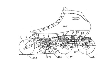
The embodimq~ts hereafter described show a roller skate with a
foot or lower leg operated self-adjusting brake and load
adjustment oaf the wheels 2,3,15,16 in order to keep contact with
0. the ground ait uneven surfaces..The roller skate is mounted to a
shoe 100,109, and fig. 1-2 is showing a three-dimensional
picture in !which a front wheel is arranged to be rigidly
attached to ',a main frame 1 in order to keep motion direction,
', while the fo~~.lowing wheels .3,15, 16 are arranged to be located in
' 15 pivoted wheel casings 4. Disc brakes 1:1 and permanent elastic
springs 7 afe attached to these wheel casings 4, Between the
main frame 1: and the wheel casings 4 equalisers 12 axe installed
in order to ',operate the disc brakes 11. The main frame l has a
pivot connection to the shoe over a base plate 29 or is directly
20 mounted to the shoe . Preferably, the basse plate is incorporated
with the shod.
Fig. 1 shoWa a three dimensional' view of the roller skate
- without the 'actual first wheel 2, the second wheel 3, the third
25 wheel 15 and the last wheel Z6 (see fig.3), the base plate 29,
which is preferably incorporated ~in the sole of shoe 100 (see
fig. 3), is connected pivotally to the main frame 1 over a hinge
30. At the :front the base plate 29 is connected to the maih
frame 1 over a hinge mechanism 14. The base plate~29 can now
30 rotate in the main frame 1, and can while doing so move a pinion
22 (see fig.', 3) of the hinge mechanism 14 from position A to H
(see fig. 4)i. The pinion 22 holds a central brake lever 13 (see
fig. 3) and moves this backwards when the base plate 29 is
' rotated in t;he main frame 1. On lever 13 axe installed three
35 pins 42 to which the topside 23 of the equalisers 12 are
' installed. Furthermore a pinion 21 is installed on lever 13,
which pinion 21 tits in a slot 27 in t;he main frame 1 and the
stroke of lever 13 is thus limited to the size of the slot 27.
On pinion 21' a permanent elastic spring 20 is installed in such
40 a way that when lever 13 is continuous7.y pressed forward, said
SUBSTITUTE SHEET (RULE 26)
CA 02318078 2000-07-20
JUL. ?.2000 4:24PM FRSTH LRW OFFICES 9042880263 N0.622 P.11i43
i~VO 99/361d2 fG'T/SE99/00033
8 -
continuous pressure works on pinion 22 (see ~ig. 3) of the
hinge mechanism 14 and presses shoe 100 with bae;e plate 29
continuously against the main frame. The first wheel 2 (see fig.
3) is fixed between a left half 43 and a right half 44 of
mainframe 1 in order to keep the direction of motion under
control. Load adjust~.ng being done by angling the foot around
the ankle 102. The second wheel 3, the third wheel 15 arid the
last wheel 16 (see fig. 3) are connected to the main frame via
the wheel casings 4 with the halves 43 and g4. The wheel casings
4 are Conn~eted pivotal to the mainframe 1 over a hinge screw 5_
On the top of the wh~el ca~rings 4 a pinion 10 is installed,
engaging the permanent elastic spring 7. The permanent elastic
spring 7 is pre-stressed between a pin 8 and a pin 9, which pins
are installed on the main frame 1, The pre-stress is, necessary
to compensate for the initial load, related to b~~dy weight,
technique and velocity of the skater, which vector-force will
work z:t 101, 106 and I07 (see fig. 3 ) . Around the centre of the
wheels 3, 15 and 16 are on a left half 45 of the w3:.ee1 casing,
the disc brakes lZ installed. To avoid the disc b7cakes ll from
2o rotating and being installed wrong, they have a hexagonal one-
way fit 57 on the left half of the wheel casing 45 (eee fig. 6).
The di9c brakes il can be moved to come in contacts with the
sides 26 of the wheels, by rotating a ring 34 (see fig. 6) The
equalisers 12 arE installed between the pins 42 on lever 13 and
the pins 47 an the brake operating ring 34. When the lever 13 is
moved backwards the egualisers 12 .will at First fol7.ow as a
whole, rotating the brake operating ring 34 in an affiliated
motion. Once contact at said side 26 is established only the top _
part 23 will continue to move, 'thereby campr~ssing .a spring 39
3o in the equaliser (see fig. 7). The compression of the spring 39
will result in an increasing pressure of disc brakes l1 towards
the wheel aides 26 and thereby creating a proportional growing
friction between the wheel sides 26 and the disc bs:ake 11 and
subsequently higher roller resistance. The initial :rotation of
ring 34, in order Go move the disc brake l1 against the surface
26 can be diyferent for the wheels 3 , 15 and 16 and depends on
how fax the braking surface 26 is worn. The afcrementioned
different distances do hardly influence the brakinc; capacity,
while the continuation of the braking stroke, by compressing
said springs 39, will give a proportional brake stroke.
SUBSTITUTE SHEET (RULE 26~
CA 02318078 2000-07-20
JUL. 7.2000 4:25PM FRSTH LRW OFFICES 9042880263 N0.622 P.12i43
WO 99l36I42 PCTlS~99/00033
9
The wheels 3, 15 and 16 have a load adjustment, in order to have
always all wheels at~the skating surface when braking, The load
adjustment does not interfere with the brake function. When a
load at for example the ground surface 101 becomes higher, the
moment of force between 101 and hinge 5 increases. To come to
equilibrium the counter moment of force between hinge 5 and
spring 7 at point 10 will have to increase in conformity. It
will do so by stretching spring 7 between pin 9 and pinion ZO
and thus increase the force on pinion l0. Hecause of the said
stretching of spring 7 the wheel 2, receiving the higher load
will move upward, to the given point. thereby dividing the
general load again relatively over all the wheel surfaces at
101-106-107 and 108 and visa versa.
Fig. 2 shows a three-dimensional view of a second embodiment of
the roller skate with removed wheels. The main frame 59 is
directly mounted to a boot half 109 I;see fig. 16). A hinge
mechanism 60 on the backside of the shoe now operates the
central brake lever 13 (see fig. 16 and 17) to move in the same
way as in the previous described embodiment, i.e. a longitudinal
motion of a force transmitting member, in these embodiments
arranged as a rigid central brake lever 13, forces a brake
operating ring 3a to rotate and thereby axially force a disc
brake 11 towards the side 26 of a rol:Ler skate wheel 3,15,16
when the skater changes the foot or leg angle towards the
skating surface. In other embodiments the force transmitting
member can be a flexible member, such as a cable.
Fig. 3 shows the roller skate~of Fig. 1 with~the wheels 2. 3, 35
and 16 in place and in contact with an uneven surface 104. The
first wheel 2 has contact with the ground over main frame 1,
. shoe 100 with base plate 29 and ankle: 102. Said contact is
necessary to keep the direction of motion under control, while
at the same time the ability of vibration insulation between the
parts is optimal. The second wheel 3 and its wheel casing 4 have
pivoted around hinge 5 to its maximum within main frame 1.
Representing a situation in which roller skating of the kind
described would be impossible, providing the interference would
repeat at a more than regular frequency. The third wheel 15 and
SUBSTITUTE SHEET (RULE 26)
CA 02318078 2000-07-20
JUL. 7.2000 4:25PM FRSTH LRW OFFICES 9042880263 NO.622 P.13i43
WO 99136142 . PCT/SE99100033
' 10
its wheel casing 4 have pivoted around hinge > half the
available distance, while, the fourth wheel 16 has remained in
neutral position. The placement of wheel 2, 3, 1S and 16
represent a practical situation and representing a dynamic
. 5 equilibrium, changing instantly with the general. operating
conditions. The wheels 2, 3, 15 and Z6 have all contact with the
surface and are in a position where braking on the wheels will
give the requested counter forc~ from the dry f~~iction the
wheels, have on the surface 104. Fig. 2 also shows the shoe 100
with the base plate 29 and the location of hinge 30. At hinge 30
the main frame 1 can pivot in respect to the base plate 29. The
wheel casing 4 of the fourth wheel 16 is in its neutral
position. Indicating that the pre-tensioning of spring 7,
between the pins a and 9 is egual or lower than thE~ result of
the moment of force between hinge 5 and reaction farce 106 on
pinion 10 of wheel casing 4. The equaliser 12 i:3 suspended
between a pin 47 of the brake operating r~i.ng 3a (see fig.9) and
pin 42 on lever 13 and is not exposed to a force :~etween the
pins 42 and 47. Tha wheel casing 4 of the third wheel 15 has
pivoted under influence of the reaction force 107_ Indicating
that the result of the moment of force between hingE~ 5 and the
reaction force 107 exceeds the pre-tension of spritZc~ 7 between
the pins 8 and 9. Causing the pinion l0 on wheel casing 4 to
move forward and tension spring 7 to such an extent that it
equals the result of the moment of~ force: between hinge 5 and
reaction force 107 on pinion 10. The pin 47 on the brake
operating ring 34 will have rotated together with wheel casing 4
around hinge 5 . Taking with it the bottom side of eq~ialiser 12 _
.. The equaliser 12 rotates around pin 42 and 'becomes a little
shorter. The change in length will not result in a Eo:rce between
the pins 42 and 47 because of the compensation space: 41 within
the equaliser 12 . ( See fig . 6 ) The wheel casing 4 of the second
wheel 3 has pivoted under the influence of reaction force 101.
Tndicating that the result o~ the moment of force be1_ween hinge
5 and reacvion force 101 exceeds the pre-tension of the spring 7
between the pins 8 and 9. Causing the pinion l0 on wheel casing
~5 to move forward and tension spring 7 to such an extent that it
equals the result of the rtoment of force between h.i.nga 5 and
reaction force l01 on pinion 10. The pin 47 on brake: operating
ring 34 will have rotated together with the wheel casing 4
SUBSTITUTE SHEET (RULE 26)
CA 02318078 2000-07-20
JUL. 7.2000 4~26PM FRSTH LRW OFFICES 9042880263 NO.622 P.14i43
'WO 99/36142 PCT/5E99/00033
11 -
around hinge 5. Taking with it the bottom part of the equaliser
12. The equaliser rotates around pin 42 and will adhere to the
same length as shown on the fourth wheel 16. The stretch
expansion of spring 7 has now come to an end, while it abuts a
buffer 50. When contact at buffer 50 as made it represents a
lifting of the wheel. Furthermore, it :is shown in fig. 2, the
' lever 13, its linkage to the frontal hinge mechanism 14 and the
three hinge pins 42 for the equaliser 12, The hinge pins 42
slide in a slot 24 in main frame 1. Shown is also a forward pin
18 and a second pin 19, which are insta:Lled on the main frame 1
and holding spring 20. Spring 20 is pre-stressed between pin l8
and 21. Pin 21 is an integral part of lever 13. Consequently
lever 13 will always be pushed forward and will exert pressure
on hinge pinion 22 and keep the shoe 100 and base plate 29 in
contact with main frame 1. Tt is under;:tood that the springs 7
and 20 are secure locked in place by a spring clip 17. The
springs 7 and 20 are located on the outside of the main frame
and can be exchanged easily, making it: possible to adapt the
bearing- and braking capacity of the skate to the individual. In
rigid in-line roller skates the wheels have all the same
diameters, in order to create an even wa_ar and thereby all-over
ground contact on all the wheels. Tn the. design at hand wear on.
the perimeter of the wheel is compensated for, thereby it
' becomes possible to fit the diameter of the wheels within the
anatomical lines of the foot. The diameter of the last wheel can
therefore be increased compared 'to the front wheels, without
.. moving the foot upwards. The increased. diamdter of the wheel
will result in a lower roller-resistance increasing the dry
friction and consequently brake capacity.
,
Fig. 3 shows the roller skate when the braking mechanism is
fully deployed, in this situation the lever 13 and pinion 22 are
moved backwards from its original posit ion symbolised by A to
' its position B. During the move from position A to B a slight
rotation around pinion 21 and vertical displacement of lever 13
' has taken place . The topside 23 of the individual equaliser has
moved and rotated around the pins 47, in coherence with said
slight rotation and in relation to the movement from A to B.
Said vertical displacement has no influence on the whole other
than a vertical enlargement of the slots 24 in the main frame.
SUBSTITUTE SHEET (RU~.E 26)
CA 02318078 2000-07-20
JUL. '7.2888 4:26PM FRSTH LRW OFFICES 9042888263 N0.622 P.15i43 '
WO 99/3612 ~PC'IYSE99~00033
12 -
It is also shown that the ground surface has a not flat profile
. and that the wheels act all at the different levels. The wheel 2
is fixed in the frame and has no brake, in order to maintain
steering capacity. In the Fig. 2 it is also suppose~3, that the
side z6 of wheel 3 is more worn, than the ones on wheel i5 and
16 (s~e fig. 6). The sides of wheel Z5 and 16 are supposad to
have worn equally, the result is represented by the distance C
and CI (see fig. g). The space 25 resembles the clearance between
disc brake and the surface of the wheel (nee ~i~~. 6y . The
movement forward of the pins ~47 has resulted in a displacement
pin 42 and rotations of the brake operating ring 34. The
rotaCion of brake operating ring 34 results in a Forward
movement (axially towards the sides of the wheels) of disc brake
12. Once said forward movement of the disc brake .2z closes
clearance 25, the spring 39 in the egualisers will start to
compress, said compression increasing the comprassicn force 55
(see f-ig.7) along the centre of a centra:L spring g~:.ide 37 and
diametrical on disc-operating ring 39~ and inex~=asing the
pressure of disc brake 11 against the wheel side 26. Resulting
2o in an increased roller resistance of the wheel, At this point it
will be very important to understand that said roller resistance
should not supersede the dry friction of the given wheel on the
skating surface, because than the wheel will block, '.'he year of
the wheel surface under the disc brake will eventual:Ly increase
the clearance 25. Requiring an increasing part of the rotation
of ring 34 to close said clearance 25. The stroke of the lever
13 has an over capacity. The distance as represented :W either C
or C1 give an indication how much, - said over capacil:y has been
used, - the brakes have worn, - 'brake capacity is le~:t . A test,
3Q to check the actual brake condition, will be to place the foot
holding the skate on the knee of the other leg and craw at the
front of the skate, in order to imitate the brake movement . The
opening remaining at either C or C2 will give a direct
indication of the braking capability left. The distance as is
represented in C is considered -maximum wear-, a mark 56 (see
fig.7) on the centre shaft 27 of the equaliser 22 ind:_cates that
the wheel has to be turned or exchanged.
Fig. 4 shows also the base plate 29 which is, ~~referably,
integrated with shoe 1~0 and hinge 30 which Connects base plate
SUBSTITUTE SHEET (RULE 26)
CA 02318078 2000-07-20
JUL. 7.2880 4:27PM FRSTH LAW OFFICES 9042880263 N0.622 P.16i43
'WO 99/36142 PCT/5E99/00033
13 '
29 pivotally on main frame 1. The front of the base plate 29
connects pivotally at a pinion 51 to a lever 52 ~of the frontal
hinge 14. Lever 52 connects at pinion 2:? with a bottom lever 53
of hinge 14. Lever 53 is pivotally connected to the mainframe 1
at a pinion 54. The pinion 22 circulates around a pinion 51 and
the pinion 54 simultaneously when the shoe 100 and base plate 29
' are rotated around hinge 30, the rotation of the shoe being
limited within the slot 27 of the main frame. The configuration
has the following targets; the mainframe 1 and base plate 29
have to be perfectly in line with each other; the mainframe and
base plate 29 have always to be pressed against one another; to
initiate braking an initial force is required; braking can be
done gradually over an on-going movement of the foot.
a ,
Fig, 5 shows a bottom view of the device shown in fig,.l with the
second wheel removed in order to show the outlines of hinge 14
bearings in place. It shows the, - base plate 29 and central
lever 13, - halves 43 and 44 of the main frame, - levers 52 and
53 of the frontal hinge mechanism 14 and the fixing points at
the hinge 5, at a front wheel bolt 6 and at the base plate hinge
which keep the construction~together. Fig. 5 also shows the
springs 7, 20 and the clips 17.
' Fig. 6 shows a sectional view over th.e centre of the fourth
25 wheel 16 of a device as shown in Fig. 1 and 3, with the
equaliser 22 removed. Said view i~s representative for the other
.. wheels equipped with brakes. Shown is a bearing for a wheel axle
comprising a scxew member 103 and a nut member 105 which bearing
has a limited and predictable axial clearance and has the
30 capacity to accept the thrust. forces generated by the disc brake
11 on the wheel surface 26. Said thrust forces will not
influence the roller resistance of the bearing. The disc brake
I1 and the left half of wheel casing 45 have a hexagonal fit, to
avoid wrong assembly. The disc L1 slides easily on the hexagonal
tap 57 of wheel casing half 45 and is pressed by a disk spring
32 against the side of the wheel casing half 45. Said spring 32
is kept in place by a spring clip 31. On the circumference of
the disc 11 are two inclining slopes 33 (see fig. e). The slopes
33 match with two inclining slopes 35 in rotating ring 34 (see
fig. 7), Between the slopes 33 and 35 a ball 49 is lodged in
SUBSTITUTE SHEET (RUSE 26)
CA 02318078 2000-07-20
JUL. 7,2880 4:27PM FRSTH LRW OFFICES 9042880263 N0.622 P.17i43 '
WO 99/36142 pC'Z'/SE99/00033
14
order to reduce friction. When the rang 34 is turned around the
disc-brake 11 it pushes the disc-brake I1 over the malls 36 and
slopes 33,35 inwards against the wheel side 26 and increases the
rol7.cr resistance of the wheel. The pressure on the disc brake
11 can be varied at the equalisers 12 over a substarctial range .
ThC friction between disc brake 11 and thw whee3 side 25 can be
kept low acrd the maximum brake output is chosen to beg lower than
the dry friction of the wheel on a standard surface, Practically
this meatZS that the brake sux~ace of disc brake 7.1 is quite
Smooth and never will need replacing. At the same time will the _
abrasion of the wheel side 26 be very Iowa. Tt is a given fact
that brake capabilities coincide with the roller skate capacity
in general. Which indicates that the number of wheels and their
respective diameter dictates the attainable speed at the cost of
flexibility etc. In the design at hand the brake ca~~acity grows
with the number of wheels and their respective: diameter.
Furthermore is shown on fig. 6, a seal 36 to avoid durst entering
and impairing the functioning of the inter-relation of the disc
11 and the ring 34. Also a left half ~5 Gf Che wheel casing is
2o shown in fig. 6.
Fig. ? shows the egualiser 22 of a device as shown in Fig. 1
with the top half 23 the central spring guide 37, a compensation
ring 38, the spring 39 and a slack 41. The equaliser rotates
simultaneously between pin 42 and 47 when the whse~_ casing is
rotated at hinge 5. The length alteration during said
simultaneous rotation is accepted at slack. ~1. It is understood
that when lever z3 is moved backwards, the disc 12 will approach
the side of the wheel 26 (see ~ig. 6). As soon as.disc 11 abuts .~
the surface 26 of the wheel, the spring 39 wil:. start to
compress drawing with its compresgiotl force at 40 and increasing
by ~-is compression the force exerted to the surface between the
wheel sid~ 26 and the disc-brake I1 (.see fig. 6).
Fig. 8 shows the disc brake 1Z of a device as shown. in Fig. I
three dimensionally, showing the sloping oonfiguratian of paths
with the inclining slope 33 around which the ba7.ls 49 are
revolving (sae fig. 6).
SUBSTITUTE SHEET (RULE 26)
CA 02318078 2000-07-20
JUL. 7.2000 4:28PM FRSTH LRW OFFICES 9042880263 N0.622 P.18i43
i~VO 99/36142 PCTl5E99100033
15 .
Fig. 9 shows the brake-operating ring of a device as shown in
fig. 7.. Ring 34, showing the sloping configuration of paths with
inclining slope 48 around which a ball is revolving. The seal 36
is aimed at keeping dust away from the fit between disc 11 and
S ring 34 and the wheel casing 45.
Fig. ZO shows a sectional view of an equaliser of a device as
shown in fig. l in the position as indicated on fig. 3 section I
enlarged. B indicates the distance between the bottom side of
equaliser 12 and the centre of pin 42.
Fig.ll shows a sectional view of an equaliser of a device as
shown in fig. 3 in the position as indicated on fig.,3 section
II enlarged. Shown is that although the equaliser 12 has been
turned an angle D, compared to Fag. 10, the length B.has stayed
the same. Proving that the up and down movement of the wheels
does not interfere by involuntary operating the brake.
Fig. 12 shows a sectional view of an equaliser of a device as
shown in fig. 1 in the position as indicated on fig. 3 section
III. Shown is again that distance B stays the same although the
equaliser 12 is turned an additional angle D1 compared to Fig.
10. Proving again that the up and down movement of the wheels
- does not interfere by involuntary operati.rig the brake.
Fig. 13 shows a sectional view of an equaliser of a device as
shown in fig. 1 in the positioy as indicated 'on fig. 4 section
VI enlarged. C1 indicates between the bottom side of equaliser
12 and the centre of pin 42. The brake disc 11 is now in contact
with the surface 26 (see fig..6). '
Fig. 7.4 shows a sectional view of an equaliser of a device as
shown in fig. 1 in the position as indicated on fig. 4 section V
enlarged. The wear on surface 26 of the wheel (see Fig. 6) is
similar to the wear in Fig. 13. Shown is that although the
' equaliser 12 has turned an angle D2, compared to Fig. 13, the
length C1 has stayed the same. Proving that the up and down
movement of the wheels, while driving an uneven surfaces, does
not interfere by in- or decreasing the se=t brake force.
SUBSTITUTE SHEET (RULE 26)
CA 02318078 2000-07-20
JUL. 7.2800 4:28PM FRSTH LRW OFFICES 9842888263 N0.622 P.19i43
WO 99136142 PCT/SE99IOOfl33
26,
Fig. 15 shows a sectional view of an equaliser of a device' as
shown is fig. 1 in the position as indicated an Fic;. 4 section
Iv enlarged. uChOWn 15 that the side 26 ~ (See Fig. 6? has worn to
such extended, that the wheels have' to be t:vrned or e:KChartged.
'
Fig. 26 shows the second. embodiment of the roller skate from
fig. 2 attached to a boot that fastens arbund the foot with the
bottom part I09 of the boot and the lower leg with t:he Cop part
110 of the boot. The two parts 109 and 110 can pivot jointly
to around each other at a boot hinge 58. The roller skate has the
following di~~erenaes compared with the embodiment shown in
Fig.l; - Both side plates 43 and 44 form now one main frame 59,
the base plate 29 and hinge, 30 are removed and - the frontal
hinge mechanism 14, which operates the Lever 13-, has been
replaced by hinge mechanism 60. All further fun=Lions with
respect to the functioning aze the same and the numbers on fig
1S correlate with the id~ntical numbers on previous figures. To
the top part 110 a profile 70 is attached, sharing a pinion 61
on the boot with a top lever 62. The lever 62 can yivot around
pinion 61. At the bottom side of lever 62 a slot 63 in lever 62
engages a pinion 64 . The pinion 64 is attached to a lever 65 _
The lever 65 is pivotally connected to a pinion 66, which is
attached to the main frame 1 over pinion 66. Another lever 67 is
connected pivotally between a pinion 69, which is attached to
tha brake operation lever 13 and a pinion 68, which is attached
to Che lever 65. A forward rotation of the upper boot will
result i.n pinion 64 sliding in slot 63 and nothing ~~ill happen,
A backward rotation of the upper boot will result in bath levers
-. 62 and 65 engaging each other around pinion ~8 and will result
in pivoting of both levers 62 and 64 around their perspective
pinions 61, 66 and their common pinion 68. During this movement
also a lever 67 will move and pivot around pinions 69 and 69,
taking with it brake operating lever 13 i1Z a straight backward
movement.
Fig, 17 represents the situation in which the top b«ot 110 has
pivoted backwards around hinge 58_ Lever 62 has rotated around
pinion 61 and taken pinion 64 with it. Constx~uct~~ng another
triangle of the levers 62 and 65 with the pinions 6,S -fixed to
the main frame 59, pinion 61-fixed to upper- boat 110- and pinion
SUBSTITUTE SHEET (RULE ~6)
CA 02318078 2000-07-20
JUL. '7.2000 4:29PM FRSTH LRW OFFICES 9042880263 N0.622 P.20i43
VVO 99/36142 - PCT/SE99100033
17
64. Caused by the outward movement of pinion 64 and the
rotation of lever 65, pinion 65 will also move outward in a
related movement, taking with it the lever 67 and its pinion 69.
The movement of pinion 69 will be followed by lever 13, which
will in its turn move the topside of the equalisers 23 and
consequently will start the braking.
In the above mentioned embodiments it is advantageous that a
locking member is arranged for blocking the disc brakes in
locked position in order to walk on t he roller skates. This
locking member is connected to the central brake lever and thus
operating on all wheels simultaneously.
SUBSTITUTE SHEET RULE 26)
CA 02318078 2000-07-20