Note: Descriptions are shown in the official language in which they were submitted.
CA 02318124 2000-07-14
W0~99/36169 PCTNS~7278
1
GAS GENERATING DEVICE WITH FLOODING CHAMBER
Technical field
The invention relates to gas generating devices of the type used i~
pressurised containers.
Background of the invention
1o Gas generating devices are widely used for producing gas, particularly in
different types of pressurised containers. Gas is usually genen~ted in such
devices by means of a reaction between two products, a first and a second
reagent. In osier to control such a reaction, it is preferred to have the
first
reagent in a first compartment, and the second reagent in a second
compartment, so that the reaction could occur only when desired by bringing
the reagents together. In order to further control the quantity of gas
produced by the reaction, it is preferred to have at least one of the iwo
reagent in the form of a flowing material, so that the reagent in the flowing
form could be handled more easily. Furthermore, if at least one reagent is in
2o a flowing form, the reaction will be favoured as the surface of reaction
between dre reagents will be greater. Once the gas is produced, it is
expelled from the device using means for egress of the gas.
CA 02318124 2000-07-14
WO 99136169 PCT/US98/27278
2
The present invention concerns a device for producing a gas, the device
. comprising a first and a second compartment, the first compartment
containing a first reagent and the second compartment containing a second
reagent, the first reagent being a flowing material, the first and the second
reagent producing the gas when reacting with each other, the device
comprising means for egress of the gas. Such a device is known from EP-A-
0 312 078.
Among the advantages of such devices is the fact that they allow control of
o gas production depending on a pressure gradient, the devices comprising a
~mpartment having a reference pressure as well as an actuator such as a
valve preventing undesired actuation. This differs from other devices such
as the device disclosed in FR-A-2 690 142, published on the 22"~ of October
1993, whereby the gas is contained at high pressure in the device, the gas
~ 5 being released when required. Indeed, devices such as disc~sed in FR-A-2
690142 require to have a substantially high pressure in the device, whereas
devices such as in EP-A-0 312 078 do not n~quire such high pressures as
the gas is produced only when needed. There are other devices, particularly
in the medical field, which are based on the same principle of using two
2o reagents and two compartments, such as the device disclosed in WO
95123641. However, the device from WO 95/23641 can be actuated only
once, by breaking a membrane separating the two reagents to start the
reaction. This differs from the device disclosed in EP-A-0 312 078, whereby
CA 02318124 2000-07-14
WA 99!36169 PGT/US98lZ7Z78
3
the reaction can be repeatedly started or stopped depending on the gas
pressure prevailing around the device. Other devices equipped with
pressure sensitive actuators are disclosed in US-A-3 178 075 or in the
pending European application of the applicant number 96870149.0, tiled on
s the 25~' of November 19~.
While having these and other advantages, two-compartments gas
generating devices, and particularly such pressure sensitive devices, have
disadvantages. Indeed, such pressure sensitive devices should be relatively
sensitive to be sufficiently efficient. Furthem~re, such devices need to
comprise a valve avoiding undesired actuation due to the orientation of the
device.
The invention seeks to provide a device of the above mentioned can which
~s is not pressure sensitive.
Summary of the invention
In acxordance with the invention, this object is accomplished in a device of
2o the above kind, in that the device further comprises a chamber, the chamber
being mobile between a first and a second position, whereby the mobile
chamber communicates with the first compartment in the first position and
with the second compartment in the second position.
CA 02318124 2000-07-14
wo ~r~~69 pcrn~s9snn~s
_. 4
A device formed in acxordance with the invention has a number of
advantages. indeed the production of gas is triggered by moon of the
chamber from the first to the second position, whereby a portion of the first
s reagent normally enters the chamber when the chamber is in the first
position, this portion of the first reagent being normally released in the
second compartment and therefore put in contact with the second reagent
when the chamber is in the second position. Therefore, such a device is not
pressure sensitive and does not require use of a valve when used for
~o regenerating pressure in an aerosol container. Indeed, the action of the
user
on the valve of the aerosol could advantageously be used for moving the
chamber. Furthermore, use of a chamber for produang the gas allows to
have an accurate control on the quantity of gas produced by the device.
Indeed, mot~n of the chamber is necessary to initisate or trigger gas
~ s production, and once production of gas is initjated, the quantity produced
is
at least limited by the quantity of first reagent which can be inserted within
the chamber and thus transferred from the first to the second compartment
for reacting.
20 detailed description of the invention
The invention will now be described by way of example and with reference
to the accompanying drawings in which:
CA 02318124 2000-07-14
Wo 99/36169 PCTNS98/Z7278
Figure 1 is a cross-sectional view of an embodiment of a device according to
the invent~n, whereby the chamber is in ttte first position.
5 Figure 2 is a cross-sectional view of the embodiment of Figure 1, whereby
the chamber is in the second position.
Figure 3 is a cross-sectional view of the embodiment of Figure 1 during gas
production.
to
Figure 4 is a cross-sectional view of another embodiment of a device
according to the invention, whereby the chamber is in the second position.
Figure 5 is a cross-sectional view of the embodiment of Figure 4, whereby
the device is tilted and the chamber is in the first position.
Figure 8 is a cross-sectional view of the embodiment of Figure 4, whereby
the chamber is in the a~econd position.
2o Figure 7 is a cross-sectional view of the embodiment of Figure 4 during gas
production.
CA 02318124 2000-07-14
WO 99/36169 PCT/US98127278
6
The device accorcfing to the invention is for producing a gas. Production of
gas is particularly useful for the pressurised containers industry. Indeed it
is
well known in the aerosol industry that there is a need to move out HFC
propellants on account of their environmental profile. The replacement
choice has mostly been the low molecular weight hydrocarbons such as
propane, butane, pentane, hexane, etc., but these are flammable gases
which may not always be suitable for use inside confined appliances with
potential ignition sources. For these reasons, the industry is seeking a
move to more environmentally friendly chemicals.
Replacing the organic propellants, such as those listed above, by non-
liqueflable propellant gases presents new problems. Unlike more
conventional liqueflable organic propellant gases, gases such as carbon
dioxide and nitrous oxide cannot be liquefied at the pressures obtainable in
an aerosol container (i.e. typically 10 to 12 bar maximum). As the product
composition is progressively emptied out of the aerosol canister the carbon
dioxide or nitrous oxide in the head-space cannot be replenished as would
be the case with liqueflable propellants, and oonsequenfly the pressure in
the head-space drops. if the head-space pressure drops too low it will no
longer be possible to dispense a product from the aerosol container.
Then3fore, the device of the invention is preferably pnxlucing COZ or N20.
CA 02318124 2000-07-14
wa~r~sm Pcrms9srin~s
7
The device comprises two compartments, each containing a reagent. The
reagents are such that they are producing the gas when reacting with each
other. A characteristic of the invention is that the first reagent is a
flowing
material. A consequence of using a flowing material for one of the reagents
s is that the surface of contact between the reagents is improved. Indeed, a
reaction would be less favoured in case of use of solid blocks of reagents,
whereby the surface of contact for the reaction would be reduced. However,
it should be noted that materials such as powders are hereby induded in
flowing materials. Indeed, The term "flowing materials" encompasses
~o materials which are flowing under gravity or may be pumped. Such materials
indude liqu~ls, pastes, gels, emulsions or powders. In a prefern3d
embodiment of the invention, the second reagent is a solid material. The
reaction between the reagents is of chemical and/or physical origin. For
example, the first and second reagents may simply dinactly chemically react
~s with each other to produce the gas, as would be the case when the first
reagent is an acid and the second a carbonate or bicarbonate, thus
produdng C02. But the chemical reaction could be indiredty caused and
due to physical reasons, as would be the case if the send reagent
contains a mixture of two sendary reagents in solid form, such as an add
2o and a carbonate or bicarbonate, whereby the first reagent is a solvent for
the
second reagent such as water for example. Indeed in such a case the actual
chemical reaction would occur between the sendary reagents and not
directly between the first and second reagents.
CA 02318124 2000-07-14
WO 99/36169 PCT/US98I27278
8
. Reagents or secondary reagents indude alkali such as carbonate or
bicarbonate. The carbonate may be used in any salt form, but sodium,
caldum and magnesium salts are preferred. Also induded are adds wh~h
s would react with alkalis, preferably selected from the group consisting of
dtric add, malic acid, malonic acid, fumaric acid, glycolic acid, tartaric
acid,
aspartic acid, succinic add, glutaric acid, adipic acid, aconic acid, ascorbic
acid, hydrochloric acid, sulphuric acid or mixtures then~of. Particularly
preferred are the organic acids, and most particularly preferred is malefic
~ o add.
The first reagent may be used in solid form, for example as a solid block or
as a tablet. The carbonate and acid may be placed in the second
compartment as discrete, preferably premixed, powders when used as
~ s secondary reagents for the second reagent. Altematirrely either or both of
the carbonate and acid may be in the form of separate tablets, or in the form
of a mixed carbonate/add tablet.
The device according to the invention comprises means for egn~rss of the
2o gas. Typically, such means are a valve which can let gas out when gas is
produced. Other means indude porous walls or wall sections for the device,
whereby the gas will flow out of the device through such porous walls or
section of walls when produced. It should be noted that such means for
CA 02318124 2000-07-14
WO 99/36169 p~.NS~~8
9
egress of the gas could also simply be a hole provided in a wall of the
. device, preferably in a wall separating the second compartment from the
outside of the device. Most preferred here are means allowing egress of gas
white preventing ingress of material, as can be achieved when using a
resilient valve for example.
The device according to the invention further comprises a chamber. The
chamber is a part comprising an internal volume. The chamber is mobile
between a first and a second position, whereby the mobile chamber
to communicates with the first compartment in the first position and with the
second compartment in the second position. During use, the chamber allows
indirect communication between the first and the second compartment.
Indeed, the first and second compartments preferably do not have direct
communication means between them, so that the first and second reagent
t 5 could react only in a controlled manner. This cor<trol of the reaction is
achieved by using the chamber as a flooding chamber, whereby it can be
completely or partially filled with the first reagent when it is ' in the
first
position, and then moved to the second position, whereby the first reagent
can flow into the second compartment containing the second reagent, thus
2o allowing occurrence of the reaction. When it is in the first position, the
chamber communicates with the first compartment. Such communication is
typically obtained by an opening in a wall of the chamber whereby the
internal volume of the chamber opens onto the first compartment when the
CA 02318124 2000-07-14
WO 99136169 PGT/US98/27278
chamber is in its first position. As the first reagent is a flowing material,
the
first relent can flow from the first compartment into the chamber when the
chamber is in the first position, the flow going through the communication
between the first compartment and the chamber. It should be noted that
s such a flow between the first compartment and the chamber may depend on
elerr~ents other th n the position of the chamber. Indeed, the first reagerit
may not completely fill the first compartment, in which case the chamber
may not be in contact with the first reagent even if it communicates with the
first compartment. Indeed the chamber may then communicate with a part of
1o the first compartment which is empty from the first reagent. In such a
case, it
may be that the device has to be tilted in a pre-determined orientation for
the
flow of the first reagent to enter the chamber. This would allow further
improved control on the occurrence of the react~n, whereby the first reagent
will enter the chamber only if the chamber is in the first position and if
tire
1s device has a pna-determined orientation.
The chamber can also be moved into a second position, whereby it is in
oommunicaflon with the second compartment. Communication between the
chamber and the second compartment may occur in the same manner than
2o communication between the chamber and the first communication, and
could for example be provided by means of an opening in a wall of the
chamber whereby the opening opens onto the first compartment when the
chamber is in the first position and onto the second compartment when the
CA 02318124 2000-07-14
Wa 99/36169 PCT/US9$t2'1Z78
11
chamber is in the second positron. The chamber should have first and
second positions such that when it communicates w~h the first compartment
it does not communicate with the second compartment and vice versa, so
that direct communication between the first and second ~mpartment could
s be avoided. Indeed; in case of a direct communication between the first and
second compartment, there would be a possibility that for example all of the
first reagent could flow down into the second compartment in an undesired
manner, thus involving production of gas in excess. Furthenrore, it is
preferred that the first reagent is not a flowing material, so that it cannot
flow
1 o into the chamber and be deposited in the first compartment. I ndeed, it is
preferred that the second reagent is in the solid form. It could also be
preferred to prevent ingress of the second reagent in the chamber by sizing
the communication between the chamber and the second compartment
appropriately, so that first reagent could flow out of the chamber into the
1 s second compartment without allowing passage of the second reagent from
the second compartment to the chamber.
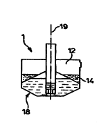
In a preferred embodiment of a device 1 ac~rcting to the invention
presented on Figure 1, the device 1 is Illustrated in the first position. In
this
2o embodiment, the chamber 16 has a cylindrical shape with a ~ngitudinal axis
19, the chamber 16 being mobile along the longitudinal axis 19, the
communication with the first compartment 11 in the first position and with the
second compartment 12 in the second posit~n being made through one or
CA 02318124 2000-07-14
WO 99/36169 PCT/US981Z7278
12
more openings 30 located at an extremity of the chamber 16. It should be
noted that a single opening 30 would be sufficient for serving as
communication means. As shown on Figure 1 whereby the chamber 16 is in
the first position, the first reagent 13 enters the chamber 16. The geometry
s of the chamber 16 and of the first compartment 11 as well as the positioning
of the openings 30 are such that the first reagent 13 enters the chamber 'f 6
or does not enter the chamber 16 depending on the orientaflon 18 of the
device 1. In another embodiment according to the invention, the first reagent
13 enters the chamber 16 when the chamber 16 is in the first position
to independently on the orientation of the chamber 16. This is obtained fior
example by using a chamber 16 having a porous wall acting as
communication means, whereby the geometry of the device 1 is such that at
least one part of the wall of the chamber 16 is in contact with the first
naagent 13 when the chamber 16 is in first position. The chamber 16 of the
~ s device 1 of Figure 1 can be moved to the second position as illustrated on
Figure 2. In this case, as some of the first reagent 13 had entered the
chamber 16 as illustrated on Figure 1, and as the chamber 16
communicates with the second compartment 12 when in the second
position, the first reagent 13 can flow through the communication means, i.
2o e. the openings 30 on Figure 2, to come into contact with the second
reagent 14 present in the second compartment 12. It should be noted that
flowing of the first reagent 13 out of the chamber 16 in the second
compartment 12 when the chamber 16 is in the second position could also
CA 02318124 2000-07-14
WO 99/36169 PCT/US98n7278
13
depend on ifie orientafron 18 of the device, depending on the geometry of
. the device 1. As the first reagent 13 is transported into the second
compartment 12 through the chamber 16, the quantity of first reagent 13
transported cannot exceed the volume inside the chamber 16. This is
important for safety reasons, whereby the amount of gas 10 produced can
be given a maximum value depending on the reagents concentrations and
on the maximum internal volume of the chamber 16. This indeed avoids
production of gas 10 in excess which could lead to an excessive pressure
rise, thus involving safety issues for a user. Indeed, the device 1 of the
1o invention aims at improving safety of users. Furthermore, as such a device
1
allows gas 10 production in a controlled manner, only the quantity of gas 10
desired can be produced, thus allowing to use reagents (13, 14) or gas 10 in
controlled amounts, thus having beneficial environmental consequences. As
shown on Figure 3, gas 10 starts being produced once the reagents (13, .14)
have been in contact. Gas 10 production may be delayed for example due to
the time needed to start dissolution if the first reagent 13 is for example a
solvent for the second reagent 14, the second reagent 14 containing a
mixture of two secondary reagents in the solid form. In particular, the second
reagent 14 could contain a first secondary reagent as an acid and a second
2o secondary reagent as a carbonate, the first reagent 13 being water. Once
gas 10 starts being produced, it can exit from the device 1 using the means
15 for egress of the gas 10 as illustrated on Figure 3. In the embodiment
presented, gas 10 is produced independently from the position of the
CA 02318124 2000-07-14
WO 99!36169 PCT/US98/Z7278
14
chamber 18 once the first 13 and second 14 reagents are in contact. In a
. preferred embodiment, a device 1 as illustrated on Figure 1 is fixed under
the valve of an aerosol container, the valve comprising a stem 17, so that
the mobile chamber 16 is faced or is part of the stem 17, in such a manner
s that displacement of the stem 17 by a user for example to expel content
from the container will induce a displacement of the chamber 16 between
first and second position or between second and first position, thus allowing
pnxluction of gas 10. For example, if the valve is on the upper side of the
aerosol container when the container is used, pressing the stem 17 would
~o bring the chamber 16 in first position as on Figure 1, while release of
pressure would bring the chamber 16 in second position as on Figure 2,
thus allowing replenishment of the gas 10 expelled during use of the
container.
15 A different geometry for a device 2 according to .the invention is
illustrated
on Figure 4. This geometry is more specifically designed for fixing the
chamber 26 to a stem 27, the stem 27 being part of a valve for a pressurised
container, whereby displacement of the stem 27 for actuafing the valve of
the pressurised container produces a displacement of the chamber 26
ao between the first and the second position. It is also possible for the
chamber
26 to be an extension of the stem 27 itself. The emb~fiment illustrated on
Figure 4 is such that the device 2 needs to be tilted as on Figure 5 to allow
entering of the first reagent 23 when the chamber 26 is in the first position.
CA 02318124 2000-07-14
WO 99/36169 pCl.NS98/Z,M~8
Indeed, the device 2 is such that the first compartment 21 is only partially
ftlled with the first reagent 23, whereby the first reagent 23 enters the
chamber 26 when the chamber 26 is in the first position and when the
device 2 has a pre-determined orientation as illustrated on Figure 5. This
5 particularly applies when using a pressurised container containing a device
2 as far example illustrated on Figure 4, whereby such the chamber 26 is
fixed to a stem 27, the stem 27 being part of a valve for the pressurised
container, whereby displacement of the stem 27 for actuating the valve of
the pressurised container produces a displacement of the chamber 26
o between the first and the second ~sition, and whereby the chamber 26 is in
the first position when the valve is opened and in the second position when
the valve is closed, the pressurised container containing a product and a
non liqueflable gaseous propellant, whereby the gas 20 produced by the
device 2 is the propellant, the gaseous propellant being above the product in
~ 5 the upper part of the container when the container is upright, the valve
allowing communication between the upper part of the container and the
outside of the container when it is opened, so that the container is nom~atly
used when tilted, whereby the pre-determined direction 28 is such that the
first reagent 23 enters the chamber 26 only when the container, and
2o consequently the device 2, is tilted, and when the chamber 26 is in the
first
position when the valve is opened. In a preferred embodiment, the device 2
is used in a pressurised container containing a foaming detergent
composition, the propellant being C02, whereby the valve communicates
CA 02318124 2000-07-14
WO 99136169 PCT/US98~12'fZ78
18
with the upper part of the inside of the container when the container is
. upright, i.e. when the end of the container comprising the valve is
upwarcis.
In such a situation, the non liquefiable propellant gaseous phase, for
example C02, is situated above the product, for example the foaming
composition. Therefore, as the valve opens on the upper part of the
~ntainer, the container should be used upside down so that the product
should be pushed through the valve by the . propellant. Therefore, normal
use of such a container is as follows: tum the container the valve facing
downwards down, press onto the stem 27 of the valve to open it, product is
1o dispensed, remove pressure on the stem 27, the valve doses back, turn the
~ntainer back upwards. When a device 2 as illustrated in Figure 4 is placed
under the stem 27, the following occurs: when the container is upright with
the valve facing upright, the device 2 is as on Figure 4, the chamber 26
being in the second position. Indeed, the chamber 26 has in this example
the second position as the default position of the chamber 26, whereby it is
held in the default pos~ion by spring means which can retain the stem 27,
thus maintaining the valve closed by default. When the container is tilted for
use, the device 2 is also tilted as illustrated on Figure 5. Furthermore, the
user presses onto the stem 27 to open the valve, so that the chamber 26
2o goes to the first position, thus letting the fast reagent 23 enter the
chamber
26. Once the user stops pressing onto the stem 27 to stop dispensing and
toms the container, and thus the device, back upright, the device 2 is as
illustrated on Figure 6, whereby the chamber 26 is in the second position.
CA 02318124 2000-07-14
WO 99136169 PCT/US98n7278
17
Gas 20 production can therefore occur, as illustrated on Figure 7. It should
be noted that an advantage of such a device 2 used in such a case is that
the quantity of gas 20 produced is proportional to the quantity of the first
reagent 23 entering the chamber 26, this quantity depending on the length
s of time during which the product is dispensed. Therefore, the more product
is dispensed, the more propellant is lost by dispensing, the more propellant
is regenerated by the device 2, while still having a maximum limit
corresponding to the maximum volume of the chamber 28 which is beneficial
for the safety of the user. In a preferred embodiment, the valve of the
~a pressurised container is a blocking valve, so that the valve can be opened
only in a pre-determined orientation, so that the propellant is not
undesirably
wasted. Such a container with a blocking valve would therefore not only
avoid waste of propellant by means of a blocking valve but would also allow
for n3-generation of used propellant by means of the device 2 of the
~s invention, thus allowing consumer satisfaction while maintaining or
improving consumer safety. Indeed, in existing cans, even when equipped
with blocking valves, pressure inside the can falls during use due to normal
use, thus involving a change of quality of the product dispensed, as would
be the case for example if dispensing a foaming composition, whereby
2o density of the foam would increase after a number of uses due to pressure
losses, wherleas such losses could be compensated using a device 2
aa;oniing to the invention.
CA 02318124 2000-07-14
WO 99/36169 PCTNS98/172?8
18
The reaction between the first (13, 23) and the second (14, 24) reagent for
- producing the gas (10, 20) can be influenced by the surface of contact
between the first (13, 23) and second (14, 24) reagents. For example, the
device 2 of Figure 4 has a surface of contact between first (13, 23) and
s second (14; 24) reagents which is relatively larger than the one on the
device 1 of Figure 1. Such a difference in surface of contact will normally
influence the speed of the reaction. Other ways to modify the surface of
intact would be for example to use porous materials or powders.