Language selection

Search

Patent 2318682 Summary

Third-party information liability

Some of the information on this Web page has been provided by external sources. The Government of Canada is not responsible for the accuracy, reliability or currency of the information supplied by external sources. Users wishing to rely upon this information should consult directly with the source of the information. Content provided by external sources is not subject to official languages, privacy and accessibility requirements.

Claims and Abstract availability

Any discrepancies in the text and image of the Claims and Abstract are due to differing posting times. Text of the Claims and Abstract are posted:

  • At the time the application is open to public inspection;
  • At the time of issue of the patent (grant).
(12) Patent Application: (11) CA 2318682
(54) English Title: TABLE UNIT
(54) French Title: UNITE DE TABLE
Status: Deemed Abandoned and Beyond the Period of Reinstatement - Pending Response to Notice of Disregarded Communication
Bibliographic Data
(51) International Patent Classification (IPC):
  • A47B 3/00 (2006.01)
  • A47B 3/06 (2006.01)
  • A47B 87/00 (2006.01)
(72) Inventors :
  • REINECKE, HARRY (Germany)
(73) Owners :
  • DAUPHIN ENTWICKLUNGS- U. BETEILIGUNGS-GMBH
(71) Applicants :
  • DAUPHIN ENTWICKLUNGS- U. BETEILIGUNGS-GMBH (Germany)
(74) Agent: MARKS & CLERK
(74) Associate agent:
(45) Issued:
(22) Filed Date: 2000-09-12
(41) Open to Public Inspection: 2001-03-18
Examination requested: 2005-08-09
Availability of licence: N/A
Dedicated to the Public: N/A
(25) Language of filing: English

Patent Cooperation Treaty (PCT): No

(30) Application Priority Data:
Application No. Country/Territory Date
299 16 465.9 (Germany) 1999-09-18

Abstracts

English Abstract


A table unit, in which table tops with pedestals can be joined to, and
detached from, each other easily and without the need of tools, comprises at
least one table top, which has at least one locking slot provided thereon;
and at least one pedestal supporting the at least one table top, the pedestal
having at least one locking bolt, which is movable into engagement with
the at least one locking slot for connection of both, and an arresting device
to be operated without tools for arresting the at least one locking bolt in
the
at least one locking slot.


Claims

Note: Claims are shown in the official language in which they were submitted.

-6-
WHAT IS CLAIMED IS
1. A table unit (1) comprising
a) at least one table top (2, 3, 4), which has
i) at least one locking slot provided thereon; and
b) at least one pedestal (5) supporting the at least one table top (2, 3,
4), the pedestal having
i) at least one locking bolt (19), which is movable into engagement
with the at least one locking slot for connection of both,
and
ii) an arresting device to be operated without tools for arresting
the at least one locking bolt (19) in the at least one locking slot.
2. A table unit (1) according to claim 1, wherein the at least one locking
slot is provided in a locking plate (22, 23, 24, 25), which is joined to the
at
least one table top (2, 3, 4).
3. A table unit (1) according to claim 1, wherein the at least one locking
slot has the shape of a keyhole.
4. A table unit (1) according to claim 1, wherein the locking bolt (19) has a
neck (20) and a head (21) joined thereto and standing out therefrom.
5. A table unit (1) according to claim 2, wherein the arresting device
comprises a shaft (13) and at least one eccentric cam disk (15), which is
joined
thereto and is pivotal from a position of assembly, in which the at least one
locking bolt ( 19) is not in arresting engagement with the at least one

-7-
locking slot, into a stop position, in which the at least one locking bolt
(19) is in
arresting engagement with the at least one locking slot.
6. A table unit (1) according to claim 5, wherein the shaft (13) is pivotal by
an operating lever (14).
7. A table unit (1) according to claim 5, wherein the at least one cam disk
(15) is supported relative to the locking plate (22, 23, 24, 25).
8. A table unit (1) according to claim 5, wherein the shaft (13) is lodged in
a housing (11) that is joined to the pedestal (5), the at least one locking
bolt
(19) being joined to the housing (11).
9. A table unit (1) according to claim 1, wherein a first table top (4) is
provided with a first locking slot and a second table top (3) is provided with
a
second locking slot, and wherein at least one pedestal (5) is provided,
having a first locking bolt (19) and a second locking bolt (19), the first
locking
bolt ( 19) being movable into engagement with the first locking slot and the
second locking bolt (19) being movable into engagement with the second
locking slot.
10. A table unit (1) according to claim 9, wherein the engagement of the
first locking bolt (19) with the first locking slot and the engagement of the
second locking bolt (19) with the second locking slot is arrested by actuation
of an arresting device.

Description

Note: Descriptions are shown in the official language in which they were submitted.


CA 02318682 2000-09-12
TABLE UNIT
BACKGROUND OF THE INVENTION
Field of the Invention
The invention relates to a table unit.
Background Art
From DE 298 22 475 Ul a table unit comprising several table tops is known,
which are connectable in series. An arresting device for connecting the table
tops is provided, which comprises an arresting hook which can be-brought into
engagement with an arresting slit. A disadvantage of this known table unit is
that the connecting mechanism does not work efficiently.
SUMMARY OF THE INVENTION
It is an object of the invention to embody a table unit in which table tops
with pedestals can be joined to, and detached from, each other easily and
without the need of tools. This object is attained in a table unit comprising
at least one table top, which has at least one locking slot provided thereon;
and at least one pedestal supporting the at least one table top, the pedestal
having at least one locking bolt, which is movable into engagement with
the at least one locking slot for connection of both, and an arresting device
to be operated without tools for arresting the at least one locking bolt in
the
at least one locking slot.. The gist of the invention resides in that, alterna-
tively, a table top can be connected to two pedestals, forming an individual
A/Li/Sc - Dauphin

CA 02318682 2000-09-12
-2-
table, or several table tops can be joined to each other with pedestals dis-
posed in between, forming a chain of tables.
Additional features and details of the invention will become apparent from
the description of an exemplary embodiment, taken in conjunction with the
drawing.
BRIEF DESCRIPTION OF THE DRAWING
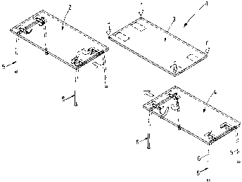
Fig. 1 is a plan view of a table unit with table tops and pedestals;
Fig. 2 is a detail, on an enlarged scale, of a pedestals with two table tops;
Fig. 3 is a cross sectional view through a table unit in the position of as-
sembly;
Fig. 4 is a sectional view on the line IV-IV in Fig. 3;
Fig. 5 is an illustration according to Fig. 3 in the stop postion; and
Fig. 6 is a sectional view on the line VI-VI in Fig. 5.
DESCRIPTION OF THE PREFERRED EMBODIMENT
As seen in Fig. 1, the table unit 1 comprises several table tops 2, 3 and 4,
which are connectable in series. The table tops 2 and 4 are supported on
pedestals 5 which are joined to the table tops 2, 3 at the frontal ends

CA 02318682 2000-09-12
-3-
thereof. By way of the pedestals S of the table tops 2 and 4, the table top 3
is supportable there-between and connectable thereto.
The pedestal 5 has two standing legs 6, which are united at their upper ends
by a supporting beam 7, as a result of which the pedestal 5 takes the shape
of a downwardly open U. Provided on the beam 7 are two transverse beams
9, 10 which are substantially perpendicular to the lengthwise extension of
the beam 7 and parallel to a longitudinal direction 8. The transverse beams
9, 10 have a tubular housing 11, the central longitudinal axis 12 of which is
parallel to the longitudinal direction 8. A shaft 13 is disposed in the hous-
ing 11; it is pivotal about the central longitudinal axis 12 and, at an end
seen on the left in Figs. 4 and 6, it is equipped with an operating lever 14,
forming a single piece therewith. A cam disk 15 is provided on each of the
ends of the housing 11, centrally comprising a hole 16 for the accommoda-
tion of the shaft 13. The cam disks 15 are tightly connected to the shaft 13.
On the side turned toward the inside of the housing 11, the cam disk 15 has
an annular groove 17 with which engages the respective lengthwise end of
the housing 11. The unit consisting of the shaft 13 and the cam disks 15 is
mounted in the housing 11 pivotally about the central longitudinal axis 12
and forms an arresting device. In the portion turned away from the housing
11, the cam disks 15 have a cam section 18 which projects lengthwise be-
yond the housing 11 and the outer circumference of which does not exhibit
a constant radius relative to the central longitudinal axis 12 and stands out
from the housing 11 at least partially in the radial direction. In a cross sec-
tion, the cam section 18 has an oval shape or the shape of an eccentric cir-
cular disk. On the upper side of the transverse beams 9 and 10, respec-
tively, three locking bolts 19 are provided, which are spaced apart equally
in the longitudinal direction 8 and are mushroom-shaped in the way of a

CA 02318682 2000-09-12
-4-
bolt head. The locking bolts 19 have a neck 20 joined to the housing 11 and
a head 21 which forms one piece therewith and stands out from the neck -
20. The head 21 and neck 20 can be solid. They may also be a plastic
sleeve which is riveted on the housing 11 by a longitudinal rivet.
In the vicinity of their two frontal ends, the table tops 3 and 4 comprise
locking plates 22, 23 and 24, 25, respectively, which are parallel to each
other. They are united with the table tops 3, 4 and comprise recesses 26
- also designates as locking slots - which are displaced relative to each
other in the longitudinal direction 8 by the same distance from each other
as the locking bolts 19. These recesses 26 have the shape of a keyhole, con-
sisting of a circular opening 27 and an adjoining oblong hole 28. The ob-
long holes 28 of the locking.plates 22, 23, 24 and 25 are unidirectional and
perpendicular to the longitudinal direction 8. Provided on the side of the
recesses 26 that is turned towards the respective table top 3 and 4 is a rear
recess 29 of sufficient depth to accommodate the respective locking bolts
19.
The following is a description of the assembly of two pedestals 5 and the
table top 4. This helps create an ordinary individual table with a table top 4
and two pedestals 5 disposed at the ends thereof, which is designated as a
table unit 1. The three locking bolts 19 of the transverse beams 9 and 10 are
pushed through the openings 27 of the locking plates 24 and 25. Then the
pedestal 5 is moved in the direction of the oblong holes 28 for the heads 21
to move into engagement with the surrounding of the oblong holes 28. In
this position, the table top 4 can no longer be pulled upwards off the lock-
ing bolt 19. For arresting, the operating lever 14 is pivoted out of the posi-
tion of assembly seen in Fig. 3 into the stop position illustrated in Fig. 5.

CA 02318682 2000-09-12
-$-
As a result, the cam section 18 of the cam disk 1$ stops on the locking plate
24 and 25, whereby the neck 20 is forced against the respective plate 24
and 2$ and the pedestal $ and the table top 4 are clamped together. The
position of the cam section 18 is selected such that in the stop position, the
portion of greatest radial distance from the axis 12 lies beyond the area of
contact between the cam disk 1$ and the locking plate 2$ in the direction of
pivoting 30. As a result, the stop position is self arresting and the
operating
lever 14 cannot disengage by itself in the stop position. For removal of the
pedestal $, the respective operating levers 14 are pivoted out of the stop
position into the position of assembly counter to the direction of pivoting
30, whereby the connection between the locking bolt 19 and the locking
plate 24 and 2$ is released and displacement of the pedestal $ in the direc-
tion toward the openings 27 and subsequent removal of the table top 4 is
possible.
1$
The following is a description of how two adjoining table tops 3 and 4 can
be united with a pedestal $. To this end, two of the three locking bolts 19
are led into the recesses 26 turned towards the end of the table top 4. The
third locking bolt 19, which is disposed at the end of the transverse beam 9
and 10 in the longitudinal direction 8, projects beyond the free end of the
table topr4. The recesses 26 disposed at each of the ends of the locking
plates 22 and 23 are moved into engagement with the above-mentioned
locking bolt 19. Then the pedestal $ is displaced in the direction of the ob-
long holes 28 and the operating lever 14 is pivoted out of the position of
2$ assembly into the stop position. The table tops 3 and 4 are now united with
a joint pedestal $. In this way it is possible to produce long chains of
tables
which can easily be assembled and disassembled. Moreover, pedestals can
be omitted in the case of long tables.

Representative Drawing
A single figure which represents the drawing illustrating the invention.
Administrative Status

2024-08-01:As part of the Next Generation Patents (NGP) transition, the Canadian Patents Database (CPD) now contains a more detailed Event History, which replicates the Event Log of our new back-office solution.

Please note that "Inactive:" events refers to events no longer in use in our new back-office solution.

For a clearer understanding of the status of the application/patent presented on this page, the site Disclaimer , as well as the definitions for Patent , Event History , Maintenance Fee  and Payment History  should be consulted.

Event History

Description Date
Application Not Reinstated by Deadline 2008-09-12
Time Limit for Reversal Expired 2008-09-12
Deemed Abandoned - Failure to Respond to Maintenance Fee Notice 2007-09-12
Inactive: IPC from MCD 2006-03-12
Letter Sent 2005-09-01
Request for Examination Received 2005-08-09
Request for Examination Requirements Determined Compliant 2005-08-09
All Requirements for Examination Determined Compliant 2005-08-09
Inactive: Cover page published 2001-03-18
Application Published (Open to Public Inspection) 2001-03-18
Inactive: First IPC assigned 2000-10-31
Inactive: IPC removed 2000-10-31
Inactive: First IPC assigned 2000-10-31
Inactive: IPC assigned 2000-10-31
Inactive: Filing certificate - No RFE (English) 2000-10-06
Filing Requirements Determined Compliant 2000-10-06
Letter Sent 2000-10-06
Application Received - Regular National 2000-10-05

Abandonment History

Abandonment Date Reason Reinstatement Date
2007-09-12

Maintenance Fee

The last payment was received on 2006-09-05

Note : If the full payment has not been received on or before the date indicated, a further fee may be required which may be one of the following

  • the reinstatement fee;
  • the late payment fee; or
  • additional fee to reverse deemed expiry.

Patent fees are adjusted on the 1st of January every year. The amounts above are the current amounts if received by December 31 of the current year.
Please refer to the CIPO Patent Fees web page to see all current fee amounts.

Fee History

Fee Type Anniversary Year Due Date Paid Date
Application fee - standard 2000-09-12
Registration of a document 2000-09-12
MF (application, 2nd anniv.) - standard 02 2002-09-12 2002-09-05
MF (application, 3rd anniv.) - standard 03 2003-09-12 2003-07-17
MF (application, 4th anniv.) - standard 04 2004-09-13 2004-07-23
Request for examination - standard 2005-08-09
MF (application, 5th anniv.) - standard 05 2005-09-12 2005-08-29
MF (application, 6th anniv.) - standard 06 2006-09-12 2006-09-05
Owners on Record

Note: Records showing the ownership history in alphabetical order.

Current Owners on Record
DAUPHIN ENTWICKLUNGS- U. BETEILIGUNGS-GMBH
Past Owners on Record
HARRY REINECKE
Past Owners that do not appear in the "Owners on Record" listing will appear in other documentation within the application.
Documents

To view selected files, please enter reCAPTCHA code :


To view images, click a link in the Document Description column. To download the documents, select one or more checkboxes in the first column and then click the "Download Selected in PDF format (Zip Archive)" or the "Download Selected as Single PDF" button.

List of published and non-published patent-specific documents on the CPD .

If you have any difficulty accessing content, you can call the Client Service Centre at 1-866-997-1936 or send them an e-mail at CIPO Client Service Centre.


Document
Description 
Date
(yyyy-mm-dd) 
Number of pages   Size of Image (KB) 
Representative drawing 2001-03-05 1 10
Description 2000-09-11 5 210
Abstract 2000-09-11 1 17
Claims 2000-09-11 2 67
Drawings 2000-09-11 4 103
Courtesy - Certificate of registration (related document(s)) 2000-10-05 1 120
Filing Certificate (English) 2000-10-05 1 163
Reminder of maintenance fee due 2002-05-13 1 111
Reminder - Request for Examination 2005-05-15 1 116
Acknowledgement of Request for Examination 2005-08-31 1 177
Courtesy - Abandonment Letter (Maintenance Fee) 2007-11-06 1 173