Sélection de la langue

Search

Sommaire du brevet 2318682 

Énoncé de désistement de responsabilité concernant l'information provenant de tiers

Une partie des informations de ce site Web a été fournie par des sources externes. Le gouvernement du Canada n'assume aucune responsabilité concernant la précision, l'actualité ou la fiabilité des informations fournies par les sources externes. Les utilisateurs qui désirent employer cette information devraient consulter directement la source des informations. Le contenu fourni par les sources externes n'est pas assujetti aux exigences sur les langues officielles, la protection des renseignements personnels et l'accessibilité.

Disponibilité de l'Abrégé et des Revendications

L'apparition de différences dans le texte et l'image des Revendications et de l'Abrégé dépend du moment auquel le document est publié. Les textes des Revendications et de l'Abrégé sont affichés :

  • lorsque la demande peut être examinée par le public;
  • lorsque le brevet est émis (délivrance).
(12) Demande de brevet: (11) CA 2318682
(54) Titre français: UNITE DE TABLE
(54) Titre anglais: TABLE UNIT
Statut: Réputée abandonnée et au-delà du délai pour le rétablissement - en attente de la réponse à l’avis de communication rejetée
Données bibliographiques
(51) Classification internationale des brevets (CIB):
  • A47B 3/00 (2006.01)
  • A47B 3/06 (2006.01)
  • A47B 87/00 (2006.01)
(72) Inventeurs :
  • REINECKE, HARRY (Allemagne)
(73) Titulaires :
  • DAUPHIN ENTWICKLUNGS- U. BETEILIGUNGS-GMBH
(71) Demandeurs :
  • DAUPHIN ENTWICKLUNGS- U. BETEILIGUNGS-GMBH (Allemagne)
(74) Agent: MARKS & CLERK
(74) Co-agent:
(45) Délivré:
(22) Date de dépôt: 2000-09-12
(41) Mise à la disponibilité du public: 2001-03-18
Requête d'examen: 2005-08-09
Licence disponible: S.O.
Cédé au domaine public: S.O.
(25) Langue des documents déposés: Anglais

Traité de coopération en matière de brevets (PCT): Non

(30) Données de priorité de la demande:
Numéro de la demande Pays / territoire Date
299 16 465.9 (Allemagne) 1999-09-18

Abrégés

Abrégé anglais


A table unit, in which table tops with pedestals can be joined to, and
detached from, each other easily and without the need of tools, comprises at
least one table top, which has at least one locking slot provided thereon;
and at least one pedestal supporting the at least one table top, the pedestal
having at least one locking bolt, which is movable into engagement with
the at least one locking slot for connection of both, and an arresting device
to be operated without tools for arresting the at least one locking bolt in
the
at least one locking slot.

Revendications

Note : Les revendications sont présentées dans la langue officielle dans laquelle elles ont été soumises.


-6-
WHAT IS CLAIMED IS
1. A table unit (1) comprising
a) at least one table top (2, 3, 4), which has
i) at least one locking slot provided thereon; and
b) at least one pedestal (5) supporting the at least one table top (2, 3,
4), the pedestal having
i) at least one locking bolt (19), which is movable into engagement
with the at least one locking slot for connection of both,
and
ii) an arresting device to be operated without tools for arresting
the at least one locking bolt (19) in the at least one locking slot.
2. A table unit (1) according to claim 1, wherein the at least one locking
slot is provided in a locking plate (22, 23, 24, 25), which is joined to the
at
least one table top (2, 3, 4).
3. A table unit (1) according to claim 1, wherein the at least one locking
slot has the shape of a keyhole.
4. A table unit (1) according to claim 1, wherein the locking bolt (19) has a
neck (20) and a head (21) joined thereto and standing out therefrom.
5. A table unit (1) according to claim 2, wherein the arresting device
comprises a shaft (13) and at least one eccentric cam disk (15), which is
joined
thereto and is pivotal from a position of assembly, in which the at least one
locking bolt ( 19) is not in arresting engagement with the at least one

-7-
locking slot, into a stop position, in which the at least one locking bolt
(19) is in
arresting engagement with the at least one locking slot.
6. A table unit (1) according to claim 5, wherein the shaft (13) is pivotal by
an operating lever (14).
7. A table unit (1) according to claim 5, wherein the at least one cam disk
(15) is supported relative to the locking plate (22, 23, 24, 25).
8. A table unit (1) according to claim 5, wherein the shaft (13) is lodged in
a housing (11) that is joined to the pedestal (5), the at least one locking
bolt
(19) being joined to the housing (11).
9. A table unit (1) according to claim 1, wherein a first table top (4) is
provided with a first locking slot and a second table top (3) is provided with
a
second locking slot, and wherein at least one pedestal (5) is provided,
having a first locking bolt (19) and a second locking bolt (19), the first
locking
bolt ( 19) being movable into engagement with the first locking slot and the
second locking bolt (19) being movable into engagement with the second
locking slot.
10. A table unit (1) according to claim 9, wherein the engagement of the
first locking bolt (19) with the first locking slot and the engagement of the
second locking bolt (19) with the second locking slot is arrested by actuation
of an arresting device.

Description

Note : Les descriptions sont présentées dans la langue officielle dans laquelle elles ont été soumises.

CA 02318682 2000-09-12
TABLE UNIT
BACKGROUND OF THE INVENTION
Field of the Invention
The invention relates to a table unit.
Background Art
From DE 298 22 475 Ul a table unit comprising several table tops is known,
which are connectable in series. An arresting device for connecting the table
tops is provided, which comprises an arresting hook which can be-brought into
engagement with an arresting slit. A disadvantage of this known table unit is
that the connecting mechanism does not work efficiently.
SUMMARY OF THE INVENTION
It is an object of the invention to embody a table unit in which table tops
with pedestals can be joined to, and detached from, each other easily and
without the need of tools. This object is attained in a table unit comprising
at least one table top, which has at least one locking slot provided thereon;
and at least one pedestal supporting the at least one table top, the pedestal
having at least one locking bolt, which is movable into engagement with
the at least one locking slot for connection of both, and an arresting device
to be operated without tools for arresting the at least one locking bolt in
the
at least one locking slot.. The gist of the invention resides in that, alterna-
tively, a table top can be connected to two pedestals, forming an individual
A/Li/Sc - Dauphin

CA 02318682 2000-09-12
-2-
table, or several table tops can be joined to each other with pedestals dis-
posed in between, forming a chain of tables.
Additional features and details of the invention will become apparent from
the description of an exemplary embodiment, taken in conjunction with the
drawing.
BRIEF DESCRIPTION OF THE DRAWING
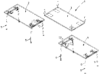
Fig. 1 is a plan view of a table unit with table tops and pedestals;
Fig. 2 is a detail, on an enlarged scale, of a pedestals with two table tops;
Fig. 3 is a cross sectional view through a table unit in the position of as-
sembly;
Fig. 4 is a sectional view on the line IV-IV in Fig. 3;
Fig. 5 is an illustration according to Fig. 3 in the stop postion; and
Fig. 6 is a sectional view on the line VI-VI in Fig. 5.
DESCRIPTION OF THE PREFERRED EMBODIMENT
As seen in Fig. 1, the table unit 1 comprises several table tops 2, 3 and 4,
which are connectable in series. The table tops 2 and 4 are supported on
pedestals 5 which are joined to the table tops 2, 3 at the frontal ends

CA 02318682 2000-09-12
-3-
thereof. By way of the pedestals S of the table tops 2 and 4, the table top 3
is supportable there-between and connectable thereto.
The pedestal 5 has two standing legs 6, which are united at their upper ends
by a supporting beam 7, as a result of which the pedestal 5 takes the shape
of a downwardly open U. Provided on the beam 7 are two transverse beams
9, 10 which are substantially perpendicular to the lengthwise extension of
the beam 7 and parallel to a longitudinal direction 8. The transverse beams
9, 10 have a tubular housing 11, the central longitudinal axis 12 of which is
parallel to the longitudinal direction 8. A shaft 13 is disposed in the hous-
ing 11; it is pivotal about the central longitudinal axis 12 and, at an end
seen on the left in Figs. 4 and 6, it is equipped with an operating lever 14,
forming a single piece therewith. A cam disk 15 is provided on each of the
ends of the housing 11, centrally comprising a hole 16 for the accommoda-
tion of the shaft 13. The cam disks 15 are tightly connected to the shaft 13.
On the side turned toward the inside of the housing 11, the cam disk 15 has
an annular groove 17 with which engages the respective lengthwise end of
the housing 11. The unit consisting of the shaft 13 and the cam disks 15 is
mounted in the housing 11 pivotally about the central longitudinal axis 12
and forms an arresting device. In the portion turned away from the housing
11, the cam disks 15 have a cam section 18 which projects lengthwise be-
yond the housing 11 and the outer circumference of which does not exhibit
a constant radius relative to the central longitudinal axis 12 and stands out
from the housing 11 at least partially in the radial direction. In a cross sec-
tion, the cam section 18 has an oval shape or the shape of an eccentric cir-
cular disk. On the upper side of the transverse beams 9 and 10, respec-
tively, three locking bolts 19 are provided, which are spaced apart equally
in the longitudinal direction 8 and are mushroom-shaped in the way of a

CA 02318682 2000-09-12
-4-
bolt head. The locking bolts 19 have a neck 20 joined to the housing 11 and
a head 21 which forms one piece therewith and stands out from the neck -
20. The head 21 and neck 20 can be solid. They may also be a plastic
sleeve which is riveted on the housing 11 by a longitudinal rivet.
In the vicinity of their two frontal ends, the table tops 3 and 4 comprise
locking plates 22, 23 and 24, 25, respectively, which are parallel to each
other. They are united with the table tops 3, 4 and comprise recesses 26
- also designates as locking slots - which are displaced relative to each
other in the longitudinal direction 8 by the same distance from each other
as the locking bolts 19. These recesses 26 have the shape of a keyhole, con-
sisting of a circular opening 27 and an adjoining oblong hole 28. The ob-
long holes 28 of the locking.plates 22, 23, 24 and 25 are unidirectional and
perpendicular to the longitudinal direction 8. Provided on the side of the
recesses 26 that is turned towards the respective table top 3 and 4 is a rear
recess 29 of sufficient depth to accommodate the respective locking bolts
19.
The following is a description of the assembly of two pedestals 5 and the
table top 4. This helps create an ordinary individual table with a table top 4
and two pedestals 5 disposed at the ends thereof, which is designated as a
table unit 1. The three locking bolts 19 of the transverse beams 9 and 10 are
pushed through the openings 27 of the locking plates 24 and 25. Then the
pedestal 5 is moved in the direction of the oblong holes 28 for the heads 21
to move into engagement with the surrounding of the oblong holes 28. In
this position, the table top 4 can no longer be pulled upwards off the lock-
ing bolt 19. For arresting, the operating lever 14 is pivoted out of the posi-
tion of assembly seen in Fig. 3 into the stop position illustrated in Fig. 5.

CA 02318682 2000-09-12
-$-
As a result, the cam section 18 of the cam disk 1$ stops on the locking plate
24 and 25, whereby the neck 20 is forced against the respective plate 24
and 2$ and the pedestal $ and the table top 4 are clamped together. The
position of the cam section 18 is selected such that in the stop position, the
portion of greatest radial distance from the axis 12 lies beyond the area of
contact between the cam disk 1$ and the locking plate 2$ in the direction of
pivoting 30. As a result, the stop position is self arresting and the
operating
lever 14 cannot disengage by itself in the stop position. For removal of the
pedestal $, the respective operating levers 14 are pivoted out of the stop
position into the position of assembly counter to the direction of pivoting
30, whereby the connection between the locking bolt 19 and the locking
plate 24 and 2$ is released and displacement of the pedestal $ in the direc-
tion toward the openings 27 and subsequent removal of the table top 4 is
possible.
1$
The following is a description of how two adjoining table tops 3 and 4 can
be united with a pedestal $. To this end, two of the three locking bolts 19
are led into the recesses 26 turned towards the end of the table top 4. The
third locking bolt 19, which is disposed at the end of the transverse beam 9
and 10 in the longitudinal direction 8, projects beyond the free end of the
table topr4. The recesses 26 disposed at each of the ends of the locking
plates 22 and 23 are moved into engagement with the above-mentioned
locking bolt 19. Then the pedestal $ is displaced in the direction of the ob-
long holes 28 and the operating lever 14 is pivoted out of the position of
2$ assembly into the stop position. The table tops 3 and 4 are now united with
a joint pedestal $. In this way it is possible to produce long chains of
tables
which can easily be assembled and disassembled. Moreover, pedestals can
be omitted in the case of long tables.

Dessin représentatif
Une figure unique qui représente un dessin illustrant l'invention.
États administratifs

2024-08-01 : Dans le cadre de la transition vers les Brevets de nouvelle génération (BNG), la base de données sur les brevets canadiens (BDBC) contient désormais un Historique d'événement plus détaillé, qui reproduit le Journal des événements de notre nouvelle solution interne.

Veuillez noter que les événements débutant par « Inactive : » se réfèrent à des événements qui ne sont plus utilisés dans notre nouvelle solution interne.

Pour une meilleure compréhension de l'état de la demande ou brevet qui figure sur cette page, la rubrique Mise en garde , et les descriptions de Brevet , Historique d'événement , Taxes périodiques et Historique des paiements devraient être consultées.

Historique d'événement

Description Date
Demande non rétablie avant l'échéance 2008-09-12
Le délai pour l'annulation est expiré 2008-09-12
Réputée abandonnée - omission de répondre à un avis sur les taxes pour le maintien en état 2007-09-12
Inactive : CIB de MCD 2006-03-12
Lettre envoyée 2005-09-01
Requête d'examen reçue 2005-08-09
Exigences pour une requête d'examen - jugée conforme 2005-08-09
Toutes les exigences pour l'examen - jugée conforme 2005-08-09
Inactive : Page couverture publiée 2001-03-18
Demande publiée (accessible au public) 2001-03-18
Inactive : CIB en 1re position 2000-10-31
Inactive : CIB enlevée 2000-10-31
Inactive : CIB en 1re position 2000-10-31
Inactive : CIB attribuée 2000-10-31
Inactive : Certificat de dépôt - Sans RE (Anglais) 2000-10-06
Exigences de dépôt - jugé conforme 2000-10-06
Lettre envoyée 2000-10-06
Demande reçue - nationale ordinaire 2000-10-05

Historique d'abandonnement

Date d'abandonnement Raison Date de rétablissement
2007-09-12

Taxes périodiques

Le dernier paiement a été reçu le 2006-09-05

Avis : Si le paiement en totalité n'a pas été reçu au plus tard à la date indiquée, une taxe supplémentaire peut être imposée, soit une des taxes suivantes :

  • taxe de rétablissement ;
  • taxe pour paiement en souffrance ; ou
  • taxe additionnelle pour le renversement d'une péremption réputée.

Les taxes sur les brevets sont ajustées au 1er janvier de chaque année. Les montants ci-dessus sont les montants actuels s'ils sont reçus au plus tard le 31 décembre de l'année en cours.
Veuillez vous référer à la page web des taxes sur les brevets de l'OPIC pour voir tous les montants actuels des taxes.

Historique des taxes

Type de taxes Anniversaire Échéance Date payée
Taxe pour le dépôt - générale 2000-09-12
Enregistrement d'un document 2000-09-12
TM (demande, 2e anniv.) - générale 02 2002-09-12 2002-09-05
TM (demande, 3e anniv.) - générale 03 2003-09-12 2003-07-17
TM (demande, 4e anniv.) - générale 04 2004-09-13 2004-07-23
Requête d'examen - générale 2005-08-09
TM (demande, 5e anniv.) - générale 05 2005-09-12 2005-08-29
TM (demande, 6e anniv.) - générale 06 2006-09-12 2006-09-05
Titulaires au dossier

Les titulaires actuels et antérieures au dossier sont affichés en ordre alphabétique.

Titulaires actuels au dossier
DAUPHIN ENTWICKLUNGS- U. BETEILIGUNGS-GMBH
Titulaires antérieures au dossier
HARRY REINECKE
Les propriétaires antérieurs qui ne figurent pas dans la liste des « Propriétaires au dossier » apparaîtront dans d'autres documents au dossier.
Documents

Pour visionner les fichiers sélectionnés, entrer le code reCAPTCHA :


Pour visualiser une image, cliquer sur un lien dans la colonne description du document. Pour télécharger l'image (les images), cliquer l'une ou plusieurs cases à cocher dans la première colonne et ensuite cliquer sur le bouton "Télécharger sélection en format PDF (archive Zip)" ou le bouton "Télécharger sélection (en un fichier PDF fusionné)".

Liste des documents de brevet publiés et non publiés sur la BDBC .

Si vous avez des difficultés à accéder au contenu, veuillez communiquer avec le Centre de services à la clientèle au 1-866-997-1936, ou envoyer un courriel au Centre de service à la clientèle de l'OPIC.


Description du
Document 
Date
(aaaa-mm-jj) 
Nombre de pages   Taille de l'image (Ko) 
Dessin représentatif 2001-03-05 1 10
Description 2000-09-11 5 210
Abrégé 2000-09-11 1 17
Revendications 2000-09-11 2 67
Dessins 2000-09-11 4 103
Courtoisie - Certificat d'enregistrement (document(s) connexe(s)) 2000-10-05 1 120
Certificat de dépôt (anglais) 2000-10-05 1 163
Rappel de taxe de maintien due 2002-05-13 1 111
Rappel - requête d'examen 2005-05-15 1 116
Accusé de réception de la requête d'examen 2005-08-31 1 177
Courtoisie - Lettre d'abandon (taxe de maintien en état) 2007-11-06 1 173