Language selection

Search

Patent 2318773 Summary

Third-party information liability

Some of the information on this Web page has been provided by external sources. The Government of Canada is not responsible for the accuracy, reliability or currency of the information supplied by external sources. Users wishing to rely upon this information should consult directly with the source of the information. Content provided by external sources is not subject to official languages, privacy and accessibility requirements.

Claims and Abstract availability

Any discrepancies in the text and image of the Claims and Abstract are due to differing posting times. Text of the Claims and Abstract are posted:

  • At the time the application is open to public inspection;
  • At the time of issue of the patent (grant).
(12) Patent: (11) CA 2318773
(54) English Title: PIPE THREADING ARRANGEMENT
(54) French Title: ENSEMBLE GUIDE-TUYAU
Status: Deemed expired
Bibliographic Data
(51) International Patent Classification (IPC):
  • H02G 1/08 (2006.01)
  • G02B 6/44 (2006.01)
(72) Inventors :
  • DELAFORCE, STEPHEN ROBERT (United Kingdom)
(73) Owners :
  • LATTICE INTELLECTUAL PROPERTY LTD. (United Kingdom)
(71) Applicants :
  • BG INTELLECTUAL PROPERTY LIMITED (United Kingdom)
(74) Agent: GOWLING WLG (CANADA) LLP
(74) Associate agent:
(45) Issued: 2003-10-28
(86) PCT Filing Date: 1999-01-19
(87) Open to Public Inspection: 1999-08-12
Examination requested: 2000-07-27
Availability of licence: N/A
(25) Language of filing: English

Patent Cooperation Treaty (PCT): Yes
(86) PCT Filing Number: PCT/GB1999/000168
(87) International Publication Number: WO1999/040661
(85) National Entry: 2000-07-27

(30) Application Priority Data:
Application No. Country/Territory Date
9802418.5 United Kingdom 1998-02-05

Abstracts

English Abstract


A pipe threading arrangement includes a launch body (13) and a parachute (15)
within tube (12). The parachute is launched into pipe (2) via slide valve (1)
and brings with it a threading cable (19). At a remote location within the
pipe (2) the parachute is stopped by a catch arm (8) with associated catch
finger (5). The parachute is deflated and retrieved, together with the
threading cable, via the slide valve into the catch body (4).


French Abstract

L'invention concerne un ensemble guide-tuyau comprenant un dispositif de lancement (13) et un parachute (15) à l'intérieur d'un tube (12). Le parachute est projeté dans un tuyau (2) grâce à un distributeur à tiroir (1), ce parachute entraînant avec lui un fil de guidage (19). Ce parachute est ensuite immobilisé, à un emplacement éloigné à l'intérieur dudit tuyau (2), par un bras de blocage (8) pourvu d'un doigt de blocage (5). Ce parachute finit par se dégonfler avant d'être retiré, avec ledit fil de guidage, par l'intermédiaire du distributeur à tiroir situé dans le dispositif de blocage (4).

Claims

Note: Claims are shown in the official language in which they were submitted.


CLAIMS

1. Pipe threading apparatus including launch means for
launching a parachute from a first location through the
pipe to a second location under fluid pressure; and
stopping means for positioning at the second location for
stopping the further passage of the parachute, the
parachute being configured to carry a cable so as to
provide a connection between the first and second
locations.

2. Apparatus as claimed in claim 1 wherein the stopping
means has an adherent surface for cooperating with an
adherent surface carried by the parachute to assist in
stopping its travel.

3. Apparatus as claimed in claim 1 wherein the stopping
means is movable perpendicular to the axis of the pipe to
automatically stop the parachute on contact with the
stopping means.

4. Apparatus as claimed in claim 1 wherein the stopping
means includes a portion moveable between a vertical and
horizontal position to allow deflation and removal of the
parachute.

5. Apparatus as claimed in claim 1 wherein the stopping
means includes a sealable chamber and valve means for
adjusting fluid pressure in the sealable chamber.

6. Apparatus as claimed in claim 1 wherein the launch
means includes a sealable chamber and valve means for
adjusting fluid pressure in the sealable chamber.

8


7. Apparatus as claimed in claim 6 wherein fluid supply
means are provided connectable to the sealable chamber to
allow fluid to pass into the chamber for pressure
adjustment and/or launch assistance.

8. Apparatus as claimed in claim 1 including a vertical
launch body moveable towards the pipe prior to launch of
the parachute.

9. Apparatus as claimed in claim 1 wherein the parachute
is configured to be automatically expanded by fluid in
the pipe at the initiation of launch.

10. A method of threading a pipe between first and second
locations comprising providing an aperture in the pipe at
first and second spaced locations, providing a stopping
device within the pipe at the second location, launching
a parachute carrying a threading cable from the first
location allowing the parachute to move to the second
location by means of fluid flow through the pipe until
stopped by the stopping device and retrieving the
parachute with the attached cable to provide pipe
threading between the first and second locations.

11. A method as claimed in claim 10 including providing
sealable chambers at the first and second locations to
allow the device to be launched and retrieved and
adjusting the pressure within the sealable chamber to
facilitate the launch and retrieval.

9


12. A method as claimed in claim 10 wherein the stopping
device is moved perpendicular to the axis of the pipe
into a stopping position.

10

Description

Note: Descriptions are shown in the official language in which they were submitted.


CA 02318773 2000-07-27
WO 99/40661 PCT/GB99/00168
PIPE THREADING ARRANGEMENT
The invention relates i.o the threading of a pipe
between two locations, the pipe typically carrying a
fluid.
In gas pipes, for example, it may be necessary to
allow an object to be towed between one location and
another in a 'live' fluid carrying condition. Such a
situation is described in copending patent application
GB 9724231.7.
The present invention is concerned with a mechanism
for allowing an initial lightweight thread or cable to
be passed between the locations prior to towing the
object between the two points.
According to the invention there is provided pipe
threading apparatus including means for launching a
parachute-like device from a first location through
the pipe to a second location under fluid pressure and
stopping means for positioning at the second location
for stopping the further passage of the parachute-like
device, the parachute-like device being configured to
carry a cable so as to provide a connection between
the first and second loca~~ions.

CA 02318773 2000-07-27
WO 99/40661 PCTIGB99/00168
The stopping means preferably has an adherent surface
for cooperating with an adherent surface carried by
the parachute-like device.
Preferably the stop~~ing means is moveable
perpendicular to the axis, of the pipe to automatically
halt the parachute-like device on contact with the
stopping means.
Further according to the invention there is provided
a method of threading a pipe between first and second
locations comprising providing an aperture in the pipe
at first and second spaced locations, providing a
stopping device within the pipe at the second
location, launching a parachute-like device carrying
a threading cable from the=_ first location allowing the
parachute to move tc the second location by means of
fluid flow through the pipe until stopped by the
stopping device and rei:rieving the parachute-like
device with the attacr,ed cable to provide pipe
threading between the first and second locations.
Preferably the method includes providing sealable
chambers at the first and second locations to allow
the device to be launched and retrieved and the step
2

CA 02318773 2000-07-27
WO 99/40661 PCT/GB99/00168
of adjusting the pressure within the sealable chamber
to facilitate the launch and retrieval.
The invention will now be' described by way of example
with reference to the accompanying drawings in which:-
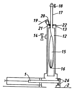
Figure 1 shows a paracaute arrangement carrying a
threading cable and a launch tube for allowing the
deployment of the parachul~e via a slide valve into the
pipeline;
Figure 2 shows the arrangement during the launch of
the parachute with the aid of compressed gas;
Figure 3 shows a stop mechanism provided at a
downstream location for swopping the parachute at the
desired point;
Figure 4 shows a detail of the stop mechanism with the
adherent surface;
Figure 5 shows the stop mechanism prior to insertion
into the pipeline; and
3

CA 02318773 2000-07-27
WO 99/40661 PCT/GB99l00168
Figure 6 shows the parachute retrieval into the catch
tube with the slide valve shut.
The pipe threading arrangement, typically utilised
under live conditions employs previously fitted slide
valves at spaced locatic>ns over apertures through the
pipeline wall using known fitting techniques.
Figure 1 shows the launcher arrangement which includes
a launch body 13 and a parachute tube 12 containing
parachute 15. The parachute carries at its front end
pieces of adherent material 16 (e.g. Velcro) for
reasons described below. At the rear end a threading
cable 19 is attached and passes via cable seal 21 to
pulley 20 so as to be played out as the parachute
moves through the gas pi~ae after launch. A gas valve
18 allows pressurised gas (e.g. nitrogen) to enter the
vertical slide tube ll for pressure equalisation
between the launcher and the gas pipe 2. An
equalisation valve I4 allows the pressure in the
launch tube following subsequent closure of the slide
valve 1 (after launch completion) to be relieved. The
slide tube 17 is sealed by seal 22 to prevent leakage
between the slide tube Gird the vertical launch body
13. The launcher is connected to slide valve 1 which
4

CA 02318773 2000-07-27
WO 99/40661 PCT/GB99/00168
is in turn affixed to the gas pipe 2. The slide valve
carries an equalisation valve 26. The slide valve can
be opened to allow the launch to commence into the gas
pipe 2.
As shown in Figure 2, to launch the device, the
equalisation valve 26 into the slide plate 1 is opened
to equalise the pressure in the gas pipe and the
launch body. When equalised, the slide valve 1 is
opened and the vertical slide tube 17 is manually
lowered so as to cause thE~ parachute tube to move past
the open slide valve 1 towards the pipe 2. Compressed
gas via valve 18 then assists in the launch causing
the parachute 15 to be blown into the pipe 2 and the
gas flowing in the pipeline causes the parachute 15 to
inflate and be carried t=hrough the pipeline by the
flowing gas to a point downstream taking with it the
threading cable 19.
At the desired retrieval point downstream a second
side valve 1 (see Fig. 3) is located which has already
in place a parachute stop mechanism (its deployment
described in more detail :~elow).
The stop mechanism includes a catch arm 8 and a catch
5

CA 02318773 2000-07-27
WO 99/40661 PCT/GB99100168
finger 5 hinged about pivot 9. The finger is operable
from a horizontal to a vertical position by a cable 6
passing through a catch rod 3 (see also Fig. 4). The
adherent material 16 on the parachute hits adherent
material 7 carried on i:he stopping face of catch arm
8 and holds the parachute at that point.
The stop mechanism wil:L have been inserted into the
pipe 2 with the catch f_Lnger in the vertical position
as shown in Figure S. This is achieved by keeping the
cable 6 pulled tight. The catch rod will be sealed
around the cable pull to prevent fluid loss. The
catch rod 3 is also sealed with the catch body by
means of seal 24. The catch rod is lowered into the
pipe 2 after valve 1 has been opened. Equalisation
valve 10 is provided far similar reasons to that in
the launch t;:be.
Returning to the capture sequence, after the parachute
15 is stopped by vertical catch arm 8, the cable pull
6 is operated to cause the parachute to deflate and
become trapped between the arm 8 and finger 5 (see
Fig. 6). The vertical catch rod 3 is then raised
taking the parachute and trailing cable 19 with it.
6

CA 02318773 2000-07-27
WO 99/40661 PCT/GB99/00168
After retrieval, the slide valve 1 is closed and the
cable is sealed by a mechanism in the valve the
subject of a copending patent application. Pressure
relief is carried out via valve 10 and the mechanism
at the retrieval encl removed to allow towing
mechanisms to be affixed as appropriate.
7

Representative Drawing
A single figure which represents the drawing illustrating the invention.
Administrative Status

For a clearer understanding of the status of the application/patent presented on this page, the site Disclaimer , as well as the definitions for Patent , Administrative Status , Maintenance Fee  and Payment History  should be consulted.

Administrative Status

Title Date
Forecasted Issue Date 2003-10-28
(86) PCT Filing Date 1999-01-19
(87) PCT Publication Date 1999-08-12
(85) National Entry 2000-07-27
Examination Requested 2000-07-27
(45) Issued 2003-10-28
Deemed Expired 2006-01-19

Abandonment History

There is no abandonment history.

Payment History

Fee Type Anniversary Year Due Date Amount Paid Paid Date
Request for Examination $400.00 2000-07-27
Registration of a document - section 124 $100.00 2000-07-27
Application Fee $300.00 2000-07-27
Maintenance Fee - Application - New Act 2 2001-01-19 $100.00 2001-01-17
Registration of a document - section 124 $50.00 2001-11-13
Maintenance Fee - Application - New Act 3 2002-01-21 $100.00 2002-01-07
Maintenance Fee - Application - New Act 4 2003-01-20 $100.00 2003-01-03
Final Fee $300.00 2003-08-06
Maintenance Fee - Patent - New Act 5 2004-01-19 $150.00 2003-12-10
Owners on Record

Note: Records showing the ownership history in alphabetical order.

Current Owners on Record
LATTICE INTELLECTUAL PROPERTY LTD.
Past Owners on Record
BG INTELLECTUAL PROPERTY LIMITED
DELAFORCE, STEPHEN ROBERT
Past Owners that do not appear in the "Owners on Record" listing will appear in other documentation within the application.
Documents

To view selected files, please enter reCAPTCHA code :


To view images, click a link in the Document Description column. To download the documents, select one or more checkboxes in the first column and then click the "Download Selected in PDF format (Zip Archive)" or the "Download Selected as Single PDF" button.

List of published and non-published patent-specific documents on the CPD .

If you have any difficulty accessing content, you can call the Client Service Centre at 1-866-997-1936 or send them an e-mail at CIPO Client Service Centre.


Document
Description 
Date
(yyyy-mm-dd) 
Number of pages   Size of Image (KB) 
Cover Page 2003-09-24 1 32
Representative Drawing 2000-10-31 1 5
Claims 2003-01-21 3 81
Representative Drawing 2003-04-03 1 5
Abstract 2000-07-27 1 43
Description 2000-07-27 7 194
Claims 2000-07-27 4 97
Drawings 2000-07-27 3 45
Cover Page 2000-10-31 1 36
Correspondence 2003-08-06 1 36
Correspondence 2003-08-12 3 115
Fees 2002-01-07 1 31
Correspondence 2000-10-11 1 2
Assignment 2000-07-27 4 137
PCT 2000-07-27 11 402
Assignment 2000-11-08 2 69
Correspondence 2000-11-08 1 31
Assignment 2001-11-13 6 176
Assignment 2002-05-07 2 56
Prosecution-Amendment 2002-10-18 2 34
Fees 2003-01-03 1 33
Prosecution-Amendment 2003-01-21 5 128
Fees 2001-01-17 1 29