Language selection

Search

Patent 2318850 Summary

Third-party information liability

Some of the information on this Web page has been provided by external sources. The Government of Canada is not responsible for the accuracy, reliability or currency of the information supplied by external sources. Users wishing to rely upon this information should consult directly with the source of the information. Content provided by external sources is not subject to official languages, privacy and accessibility requirements.

Claims and Abstract availability

Any discrepancies in the text and image of the Claims and Abstract are due to differing posting times. Text of the Claims and Abstract are posted:

  • At the time the application is open to public inspection;
  • At the time of issue of the patent (grant).
(12) Patent Application: (11) CA 2318850
(54) English Title: ELECTRIC LAMP FOR A VEHICLE HEADLIGHT
(54) French Title: LAMPE ELECTRIQUE POUR UN PHARE DE VEHICULE
Status: Deemed Abandoned and Beyond the Period of Reinstatement - Pending Response to Notice of Disregarded Communication
Bibliographic Data
(51) International Patent Classification (IPC):
  • H01J 05/54 (2006.01)
  • H01K 01/46 (2006.01)
(72) Inventors :
  • HELBIG, PETER (Germany)
(73) Owners :
  • PATENT-TREUHAND-GESELLSCHAFT FUER ELEKTRISCHE GLUEHLAMPEN MBH
(71) Applicants :
  • PATENT-TREUHAND-GESELLSCHAFT FUER ELEKTRISCHE GLUEHLAMPEN MBH (Germany)
(74) Agent: SMART & BIGGAR LP
(74) Associate agent:
(45) Issued:
(86) PCT Filing Date: 1999-11-26
(87) Open to Public Inspection: 2000-06-08
Availability of licence: N/A
Dedicated to the Public: N/A
(25) Language of filing: English

Patent Cooperation Treaty (PCT): Yes
(86) PCT Filing Number: PCT/DE1999/003762
(87) International Publication Number: DE1999003762
(85) National Entry: 2000-07-21

(30) Application Priority Data:
Application No. Country/Territory Date
198 55 403.6 (Germany) 1998-12-01

Abstracts

English Abstract


The invention relates to lamp for a headlight of a vehicle comprising a metal-
plastic socket. The lamp socket comprises a metallic holder (14a-14e) for the
lamp bulb (10) and a plastic socket part (15) which is provided with the
electrical contacts (16, 17) of the lamp. The metallic holder (14a-14e) is
anchored in said plastic socket part (15). A sealing ring (19) formed of
silicone or rubber is used for sealing the reflector opening which is
configured as the lamp socket. The sealing ring (19) is arranged between the
outer wall of the reflector (20) and the ring-shaped flange (15a) of the
plastic socket part (15). According to the invention, the upper surface of the
ring-shaped flange facing the lamp bulb (10) is provided with a light-
reflecting coating.


French Abstract

L'invention concerne une lampe pour un projecteur de véhicule, équipée d'un culot en métal et en plastique. Ce culot présente une fixation métallique (14a-14e) l'ampoule (10) de la lampe, et une partie de culot en plastique (15) comportant les raccordements électriques (16, 17) de la lampe, la fixation métallique (14a-14e) étant ancrée dans ladite partie de culot. Une bague d'étanchéité (19) en silicone ou en caoutchouc, placée entre la paroi extérieure de réflecteur (20) et la bordure annulaire (15a) de la partie de culot en plastique (15) sert à assurer l'étanchéité de l'ouverture de réflecteur se présentant sous la forme d'une douille de lampe. Selon l'invention, le côté supérieur orienté vers l'ampoule (10), de la bordure annulaire (15a), présente un revêtement réfléchissant la lumière.

Claims

Note: Claims are shown in the official language in which they were submitted.

-5-
Claims
1. Electric lamp for a vehicle headlight, having a
lamp cap, a transparent lamp bulb (10) and at
least one luminous means (11) surrounded by the
lamp bulb (10), the lamp cap having a plastic cap
part (15), provided with the electric terminals
(16,17) of the lamp, and at least one metallic
holder part (14a-14e), anchored in the plastic cap
part (15), for the lamp bulb (10), characterized
in that the surfaces (15a) of the plastic cap part
(15) which face the lamp bulb (10) are provided
with an optically reflecting coating (21).
2. Electric lamp according to Claim 1, characterized
in that the optically reflecting coating (21) is
an aluminium layer.
3. Electric lamp according to Claim 2, characterized
in that the optically reflecting coating (21) is
an aluminium-containing paint layer.
4. Electric lamp according to Claim 2, characterized
in that the optically reflecting coating (21) is
an aluminium sheet which covers the plastic
surfaces (15a) which face the lamp bulb, and whose
side facing the lamp bulb is polished.
5. Electric lamp according to Claim 1, characterized
in that the optically reflecting coating (21)
comprises a steel sheet which covers the plastic
surfaces (15a) facing the lamp bulb.

Description

Note: Descriptions are shown in the official language in which they were submitted.


CA 02318850 2000-07-21
Electric lamp for a vehicle headlight
The invention relates to an electric lamp for a vehicle
headlight in accordance with the preamble of Patent
Claim 1.
I. Prior Art
Such an electric lamp is disclosed, for example, in the
International Patent Application WO 97/25733. This
laid-open patent application describes an electric
incandescent lamp, in particular a motor vehicle
headlight, having an incandescent filament enclosed in
a vitreous lamp bulb, and a lamp cap comprising metal
parts and plastic parts. The pinch foot, sealed in a
gastight fashion, of the lamp bulb is fixed in a
metallic holder part which, for its part, is connected
directly or via an intermediate ring to a metallic,
annular support sleeve. The metallic support sleeve is
anchored in the plastic cap part of the lamp cap, which
is fitted with the electric terminals of the lamp. In
order to mount the lamp in the opening, constructed as
lamp mount, of a reflector, the annular support sleeve
has three reference noses, which are arranged in one
plane are distributed equidistantly over the
circumference of the support sleeve, and engage in the
lamp mounting opening of the reflector, and a press-on
spring which acts radially outwards and bears
resiliently against the edge of the lamp mounting
opening of the reflector. The sealing of the mounting
opening of the reflector is performed by means of a
silicone ring or rubber ring which is arranged between
the reflector outer wall and the annular flange of the
plastic cap part. The disadvantage of this lamp
consists in that the plastic surface of the flange is
accessible for the electromagnetic radiation emitted by

CA 02318850 2000-07-21
- 2 -
the incandescent filament through the mounting opening
of the reflector. This plastic surface is heated by the
infrared radiation emitted by the incandescent filament
and, in addition, by the absorption of the light
produced by the incandescent filament, and tends to
vaporize. Moreover, the aforementioned light absorption
reduces the efficiency of the headlight.
II. Summary of the Invention
It is the obj ect of the invention to provide a vehicle
headlight lamp which when used in a headlight ensures a
reduced vaporization behaviour and an improved
efficiency.
The object is achieved according to the invention by
means of the characterizing features of Patent Claim 1.
Particularly advantageous designs of the invention are
described in the subclaims.
The vehicle headlight lamp according to the invention
has a lamp cap, a transparent lamp bulb and at least
one luminous means surrounded by the lamp bulb, the
lamp cap having a plastic cap part, provided with the
electric terminals of the lamp, and at least one
metallic holder part, anchored in the plastic cap part,
for the lamp bulb. According to the invention, the
surfaces of the plastic cap part which face the lamp
bulb are provided with an optically reflecting coating.
The optically reflecting coating reduces the light
absorption of the plastic cap part, and thereby reduces
the thermal loading of the latter- and consequently
improves the vaporization behaviour of the plastic cap
part. In addition, the optically reflecting coating
increases the efficiency of the headlight, since the
light impinging on the plastic surfaces is now rendered
useful for the headlight reflector by the optically
reflecting coating thereof.

CA 02318850 2000-07-21
- 3 -
The optically reflecting coating is advantageously
designed as an aluminium layer, because the latter has
a degree of optical reflection as high as the headlight
reflector, and adheres satisfactorily to the plastic
cap part. For reasons of production engineering, the
aluminium layer is advantageously designed as an
aluminium-containing paint layer. Alternatively, the
aluminium layer can advantageously also consist of an
aluminium sheet which covers the plastic surfaces of
the lamp cap which face the lamp bulb, and whose side
facing the lamp bulb is polished.
III. Description of the preferred embodiment
The invention is explained in more detail below with
the aid of a preferred exemplary embodiment. In the
drawing:
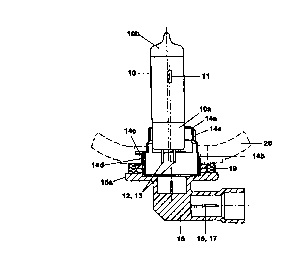
Figure 1 shows a diagrammatic, partially sectioned
illustration of the preferred exemplary
embodiment of the lamp according to the
invention, and
Figure 2 shows a top view of the plastic cap part,
and the support sleeve of the lamp
illustrated in Figure 1.
The preferred exemplary embodiment of the invention is
a single-filament halogen lamp which is provided for
use in a motor vehicle headlight. This lamp has a
vitreous, essentially cylindrical lamp bulb 10 with a
pinch foot l0a sealed in a gastight. fashion. The dome
lOb of the lamp bulb 10 is provided with an optically
absorbing coating. Serving as light source is an
incandescent filament 11, which is aligned parallel to
the lamp bulb axis and is connected in an electrically
conducting fashion to two supply leads 12,13 which are
guided out of the pinch foot 10a and consist of
molybdenum wire. The pinch foot 10a of the lamp bulb 10

CA 02318850 2000-07-21
- 4 -
is fixed in a metallic holder, which comprises the cup-
shaped holder part 14a, the intermediate ring 14e and
the annular support sleeve 14b. In addition to the
metallic holder 14a, 14b, the lamp cap also has a
plastic cap part 15, which is provided with electric
terminals 16, 17 of the lamp and in which the annular
metallic support sleeve 14d is anchored. The support
sleeve 14b has three reference noses 14c, lying in a
plane and a press-on spring 14d for mounting the lamp
in the reflector 20 of a motor vehicle headlight. The
sealing of the reflector 20 is performed by means of a
silicone sealing ring 19 which bears against the outer
wall 20b of the reflector 20 and against the annular
flange 15a of the plastic cap part 15. The design of
the lamp in accordance with the preferred exemplary
embodiment, and its use in a headlight are illustrated
diagrammatically in Figure 1. The top side of the
annular flange 15a, which faces the lamp bulb 10, is
printed with an optically reflecting, aluminium-
containing, paint layer 21 (Figure 2j which essentially
has the same degree of optical reflection and the same
hue as the reflector 20.
The invention is not restricted to the exemplary
embodiment explained in more detail above. For example,
instead of the application of a paint layer, it is also
possible to carry out vapour deposition of an aluminium
layer on the topside of the annular flange 15a. A
further alternative to the paint layer is to cover the
topside of the annular flange 15a with an aluminium
sheet whose surface facing the lamp bulb is polished.
Instead of an aluminium layer, it is also possible for
the topside of the annular flange 15a to be provided
with a different metallic coating, if the latter has a
similarly high degree of reflection as the reflective
surface of the headlight reflector. For example, the
reflecting coating 21 can also comprise a steel sheet
which covers the topside of the annular flange 15a
which faces the lamp bulb.

Representative Drawing
A single figure which represents the drawing illustrating the invention.
Administrative Status

2024-08-01:As part of the Next Generation Patents (NGP) transition, the Canadian Patents Database (CPD) now contains a more detailed Event History, which replicates the Event Log of our new back-office solution.

Please note that "Inactive:" events refers to events no longer in use in our new back-office solution.

For a clearer understanding of the status of the application/patent presented on this page, the site Disclaimer , as well as the definitions for Patent , Event History , Maintenance Fee  and Payment History  should be consulted.

Event History

Description Date
Application Not Reinstated by Deadline 2004-11-26
Time Limit for Reversal Expired 2004-11-26
Deemed Abandoned - Failure to Respond to Maintenance Fee Notice 2003-11-26
Inactive: Cover page published 2000-10-27
Inactive: First IPC assigned 2000-10-24
Letter Sent 2000-10-11
Inactive: Notice - National entry - No RFE 2000-10-11
Application Received - PCT 2000-10-06
Application Published (Open to Public Inspection) 2000-06-08

Abandonment History

Abandonment Date Reason Reinstatement Date
2003-11-26

Maintenance Fee

The last payment was received on 2002-11-04

Note : If the full payment has not been received on or before the date indicated, a further fee may be required which may be one of the following

  • the reinstatement fee;
  • the late payment fee; or
  • additional fee to reverse deemed expiry.

Patent fees are adjusted on the 1st of January every year. The amounts above are the current amounts if received by December 31 of the current year.
Please refer to the CIPO Patent Fees web page to see all current fee amounts.

Fee History

Fee Type Anniversary Year Due Date Paid Date
Registration of a document 2000-07-21
Basic national fee - standard 2000-07-21
MF (application, 2nd anniv.) - standard 02 2001-11-26 2001-11-06
MF (application, 3rd anniv.) - standard 03 2002-11-26 2002-11-04
Owners on Record

Note: Records showing the ownership history in alphabetical order.

Current Owners on Record
PATENT-TREUHAND-GESELLSCHAFT FUER ELEKTRISCHE GLUEHLAMPEN MBH
Past Owners on Record
PETER HELBIG
Past Owners that do not appear in the "Owners on Record" listing will appear in other documentation within the application.
Documents

To view selected files, please enter reCAPTCHA code :


To view images, click a link in the Document Description column. To download the documents, select one or more checkboxes in the first column and then click the "Download Selected in PDF format (Zip Archive)" or the "Download Selected as Single PDF" button.

List of published and non-published patent-specific documents on the CPD .

If you have any difficulty accessing content, you can call the Client Service Centre at 1-866-997-1936 or send them an e-mail at CIPO Client Service Centre.


Document
Description 
Date
(yyyy-mm-dd) 
Number of pages   Size of Image (KB) 
Representative drawing 2000-10-26 1 5
Abstract 2000-07-20 1 68
Description 2000-07-20 4 184
Drawings 2000-07-20 2 29
Claims 2000-07-20 1 34
Notice of National Entry 2000-10-10 1 193
Courtesy - Certificate of registration (related document(s)) 2000-10-10 1 120
Reminder of maintenance fee due 2001-07-29 1 112
Courtesy - Abandonment Letter (Maintenance Fee) 2004-01-20 1 176
Reminder - Request for Examination 2004-07-26 1 117
PCT 2000-07-20 8 290