Note: Descriptions are shown in the official language in which they were submitted.
CA 02318994 2000-07-25
WO 99/41'194 PC"T/US99/02927
PRISMATIC ELECTROCHEMICAL CELL
Backeround of the Invention
The present invention relates to sealed, prismatic electrochemical cells.
Cylindrical electrochemical cells have a cylindrical housing. Some
cylindrical cells contain a roll of thin, flexible electrodes wound up
together with a
separator layer in between them. This cell construction is sometimes called a
"jelly
roll' ; due to the wound configuration of the electrode and separator
components. The
electrodes of such cells can be made by impregnating porous, sintered metallic
place
substrates with active material, or by applying a paste containing active
material onto
a metallic substrate. Some other cylindrical cells contain pressed active
material
powder pellet electrodes arranged in concentric cylinders within the housing,
with a
separator tube between the opposing electrodes. Cylindrical cells can be
relatively
inexpensive to make, and the cylindrical shape of the can resists stress
concentrations
and deformation from internal pressure changes. Standard size AA and A nickel
cadmium (NiCd) and nickel metal hydride (NiMH) batteries are examples of wound-
type cylindrical cells. Standard AA, C and D alkaline batteries are examples
of
bobbin-type (pellet) cylindrical cells.
Prismatic cells, cells with housings with polygonal side walls (such as
parallelepiped or rectangular housings), are found in many applications
requiring high
power densities, as their shape can provide high volumetric stacking
efficiency in
battery packs, such as for cellular phones, for instance. A typical F6 nickel
metal
hydride prismatic cell has three nickel hydroxide positive electrode places
sandwiched
between four metal hydride alloy negative electrode plaques, with separator
bags
isolating each plaque layer from the next. This electrode stack is inserted
into a
rectangular metal can, with all of the negative electrode plaques connected to
one
terminal through a series of metallic tab strips, and all of the positive
electrode
plaques connected through a series of tab strips to the other terminal. Each
of the
metallic tab strips is sufficiently insulated to prevent internal shorting
between
electrode components. Generally, the can itself is one of the two terminals.
Prismatic cells are generally more complex and expensive than comparable
cylindrical
cells, due to the larger number of internal components and attendant assembly
operations.
CA 02318994 2000-07-25
WO 99/41794 PCTNS99/02927
-2-
Two important performance characteristics for a battery pre its overall
capacity (expressed in amp-hours) and its discharge efficiency at a given
discharge
rate. The rated capacity is a measure of the total amount of usable energy
stored in
the cell, and relates to the number of hours the cell can power a given load.
Capacity
is primarily a function of the amount of reactable active material contained
within the
cell, particularly the amount of whichever active material is first consumed.
Typically, cell capacity is measured at a CIS discharge rate, as described in
ANSI
C18.2M-1991, published by the American National Standards Institute. The
theore-
tical volumetric capacity of a single electrode is the total energy density of
the active
material contained within a given volume of the electrode, and can be
expressed in
ampere-hours per liter. Discharge rate efficiency is affected by the amount of
interfacial surface area between the electrodes, and the subsequent degree of
polarization which tends to reduce output voltage as the discharge rate
increases. The
more the interfacial surface area, the higher the discharge rate maintainable
above a
given voltage, as the discharge rate can be seen as a maximum current per unit
of
interfacial surface area (current density). A standard nickel metal hydride F6
cell, for
instance, may have a total of 32 or more square centimeters of interfacial
area
between the stacked electrodes.
Polarization, which generally refers to the difference in the open circuit
and closed circuit load voltage of the cell, is a function of the current
density and
consists of three separate terms: activation polarization, ohmic polarization,
and
concentration polarization. Activation polarization reduces the load voltage
at a given
load, and is an inherent function of the properties of the active materials
chosen for
the cell. Ohmic polarization also reduces the load voltage at a given rate due
to the
collective resistance contributions of the individual cell components,
connections and
interfaces, and can be reduced by lowering the resistivity of the individual
cell
components and interfaces. Concentration polarization reduces the load voltage
due
to diffusion rate limitations of charged ions in and out of the electrode
places at the
interface of the electrolyte and electrode surface, and can be reduced by
improving
the electrode reaction efficiency which in turn enhances the diffusion rate of
charged
ions within the electrode.
If the capacity of the cell is governed by the amount of active material
CA 02318994 2000-07-25
WO 99141794 PCT/U899/02927
-3-
in the positive electrode, the cell is said to be of a positive electrode-
limited type.
Cells which are designed to consume the negative active material first are
called
negative electrode-limited. Typical nickel-metal hydride cells, for instance,
are
positive electrode-limited to reduce the chance of overpressurization if the
cell is
overcharged. As the cell is charged, oxygen is generated on the surface of the
nickel
hydroxide positive electrode and subsequently reduced by the metal hydride
negative
electrode. If the positive electrode is not charged up before the negative
electrode,
hydrogen gas can form at the negative electrode, resulting in high internal
pressure.
A typical ratio of negative-to-positive capacity is more than 1.6. In other
words, a
650 milliampere-hour cell will typically contain enough negative active
material (e.g.,
metal hydride alloy) to store 1040 milliampere-hours of energy. Some of this
excess
negative capacity is lost due to corrosion of the metal hydride alloy in the
cell
environment over the life of the cell.
Summary of the Invention
The invention features a sealed prismatic electrochemical cell with
electrodes having porous structures filled with active material.
According to one aspect of the invention, the sealed electrochemical
cell includes a prismatic housing defining an internal cavity, a negative
electrode
plate disposed within the housing cavity and in electrical communication with
the
housing, and a positive electrode plate having a porous structure disposed
within the
housing cavity. The porous structure is electrically isolated from the housing
and the
negative electrode plate, and defines a principle direction of ion flow. The
maximum
linear dimension of the porous structure in the principle direction of ion
flow is at
least 20 percent (preferably at beast 30 percent, more preferably at least 40
percent,
and most preferably between about 52 and 56 percent) of the maximum linear
dimension of the housing cavity in the principle direction of ion flow.
In some embodiments, the overall external dimension of the housing,
measured in the principle direction of ion flow, is between about 2 and 8
millimeters
(preferably between about 4 and 6 millimeters, and more preferably about 5.6
millimeters).
The porosity of the porous structure of the positive electrode plate is
preferably between about 30 and 40 percent (more preferably between about 34
and
CA 02318994 2000-07-25
WO 99/41794 PCT/US99/02927
-4-
36 percent).
In some embodiments, the positive electrode plate includes an active
metallic hydroxide compound containing nickel and from zero to about four
percent
(in some cases, about two percent and in some other cases about 0.5 percent),
by
weight, cobalt. The cobalt may be in the form of cobalt oxide, the weight of
the
cobalt oxide being between about 0.03 and 0.10 times the weight of the active
metallic hydroxide compound. The active metallic hydroxide compound preferably
further contains from zero to about eight percent (more preferably between
about 4
and 6 percent, most preferably about 5 percent), by weight, zinc.
The active metallic hydroxide compound also contains, in some
embodiments, at least about 50 percent (preferably at least 55 percent, more
preferably between about 56 and 58 percent), by weight, nickel.
In some embodiments, the cell also contains a separator between the
negative arid positive electrodes, the separator having a thickness of between
about
0.12 and 0.20 millimeters. Preferable separator materials include nonwoven
fabrics
containing polyolefin. The separator has, in some cases, an average pore size
of
between about 6 and 30 microns.
In some embodiments, the void volume of the separator is less than
about 30 percent (preferably less than about 20 percent) of the sum of the
void
volumes of both electrodes and separator.
The active metallic hydroxide compound, in some embodiments, has an
aggregate surface area of between about 10 and 30 square meters per gram
(preferably about is square meters per gram). In one preferred configuration,
the
active metallic hydroxide compound is spheroidal, has a tap density (as
defined by
ASTM:D52'7-93) of between about 1.8 and 2.2 grams per cubic centimeter, and
has a
D 101 crystallite plane spacing of less than about 100 angstroms.
In some embodiments, the negative electrode plate is U-shaped, having
a central portion and two arms extending from the central portion on opposite
sides
of the positive electrode plate. The central portion of the U-shaped negative
electrode
plate may be welded to the housing.
In some embodiments, the ratios of the total capacities of both the
positive and negative electrode plates, at a C/S discharge rate, to the volume
of the
CA 02318994 2000-07-25
WO 99/41794 PC'T/US99/02927
-5-
housing cavity each exceed about 100 ampere-hours per liter. Preferably, these
ratios
exceed about 150 ampere-hours per Liter (more preferably about 250 ampere-
hours
per Iiter).
According to another aspect of the invention, the sealed electro-
chemical cell includes a prismatic housing defining an internal cavity, a
negative
electrode plate disposed within the housing cavity and in electrical
communication
with the housing, and only one positive electrode plate having only one,
unitary,
porous structure disposed within the housing cavity. The porous structure is
electrically isolated from the housing and the negative electrode plate, and
defines a
principle direction of ion flow. The maximum linear dimension of the porous
structure in the principle direction of ion flow is at least 15 percent of the
maximum
linear dimension of the housing cavity in the principle direction of ion flow.
According to another aspect of the invention, a miniature electro-
chemical cell is provided for use in portable electronic equipment. The cell
has a
1 S prismatic housing defining an internal cavity with a volume of less than
about 20
cubic centimeters, an outer electrode disposed within the housing cavity, and
an inner
electrode adjacent the outer electrode. The inner and outer electrodes
together define
a principle direction of ion flow, the inner electrode having a thickness of
at least 1.0
millimeter in the principle direction of ion flow.
Some embodiments of the cell are constructed to produce a sustained
electrical current of at least about 80 milliamperes (preferably, at least
about 100
milliamperes, more preferably at least about 120 milliamperes) per square
centimeter
of the cross-sectional area of the inner electrode perpendicular to the
principle
direction of ion flow, at a voltage above about 1.0 volt.
In some configurations, the ratio of the total capacity of each of the
anode and cathode to the volume of the housing cavity exceeds about 275 ampere-
hours per liter.
According to another aspect of the invention, the sealed electro-
chemical cell has a prismatic housing with an internal cavity volume of less
than
about 20 cubic centimeters, the maximum linear dimension of the porous
structure in
the principle direction of ion flow being at Least 20 percent of the maximum
linear
dimension of the housing cavity in the principle direction of ion flow.
CA 02318994 2000-07-25
WO 99!41794 PCT/US99l02927
-6-
According to yet another aspect, a nickel electrode plague is provided
for use in a nickel metal hydride electrochemical cell. The place contains a
porous
metallic substrate, and a metallic hydroxide compound disposed within the
cavities of
the substrate. The compound is of spherical powder form and contains at least
50
percent nickel in the form of nickel hydroxide. The plaque has a thickness of
between about 0.5 and 3 millimeters, and a total volumetric capacity of at
least 560
ampere-hours per liter.
According to yet another aspect, a metal hydride electrode plaque is
provided for use in a nickel metal hydride electrochemical cell. The plaque
contains
a porous metallic substrate, and a nickel metal hydride compound disposed
within the
cavities of the substrate. The' plaque has a thickness of between about 0.5
and 3
millimeters, and a total theoretical volumetric capacity of at least 1000
ampere-hour
per liter.
Various aspects of the construction of the electrode and the cell
together enable high internal current densities (and resulting discharge
rates) while
achieving very high capacity.
Various implementations of the invention may provide an electro-
chemical cell with a very low percentage of internal volume taken up by
inactive
materials, such as interconnecting tabs and multiple separator layers, leaving
a high
percentage of the internal volume for active material. The simple construction
of the
cell can also provide for efficient and inexpensive manufacture and assembly,
which
can result in minimal scrap and low cost. The invention can provide high
energy
densities, particularly for rechargeable applications which do not require
extremely
high discharge rates. In addition, the internally limited maximum discharge
rate can
help to protect the battery against overheating if externally shorted.
Other advantages and embodiments will be apparent from the
following description of drawings, and from the claims.
Brief Description of the Drawings
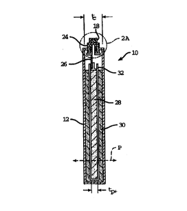
Fig. 1 is a perspective view of a prismatic electrochemical cell.
Fig. 2 is a section view of the cell of Fig. 1, showing one electrode
configuration.
Fig. ZA is an enlarged view of area 2A in Fig. 2.
CA 02318994 2000-07-25
WO 99/41794 PCT/US99/02927
-7_
Fig. 3 is a view of spherical metal hydroxide alloy powder, enlarged
4000X.
Fig. 3A is a view of the powder of Fig. 3, enlarged 10,000X.
Fig. 3B is a view of the powder of Fig. 3, enlarged 100,000X.
Figs. 4A-4F sequentially illustrate the production of a positive
electrode plaque.
Figs. SA-SD sequentially illustrate the production of a negative
electrode plaque.
Figs. 6A-6C illustrate other electrode configurations.
Description. of Embodiments
Referring to Fig. 1, a miniature prismatic nickel metal hydride rechar-
geable cell IO has a rectangular can or housing 12 of nickel-plated cold
rolled steel,
stamped or deep drawn as known in the art. Cell 10 is of the F6 size used in
some
portable communications equipment, having an overall length, L, of between
about 48
and 50 millimeters, a width, W, of between 15 and 16 millimeters, and an
overall
thickness, T, of about 5.6 millimeters. Because of its thinness, an array of
such cells
can be packaged in such devices as thin portable telephones and computer
equipment.
The thickness of cell 10 is preferably about 2 to 8 millimeters, more
preferably
between about 4 and 6 millimeters.
Referring also to Fig. 2, one end of housing 10 is solid, while the other
is capped with a cap assembly 14 which includes a cap plate 16 and to which a
contact button 18 is attached. Cap plate 16 is laser welded to can 12 along
seam 20,
such that the entire battery is sealed. The cavity within can 12 has an
overall cavity
thickness tc of about 4.6 millimeters. The principle direction of ion flow
(i.e., the
direction normal to the inter-electrode interface between opposing electrode
surfaces)
is indicated by arrow P.
Referring also to Fig. 2A, contact button 18 is welded to a rivet 24
which is sealed to, and electrically isolated from, cap plate 16 by a nylon
seal 22.
Seal 22 sits within a recess in plate 16 and is held in place by rivet 24,
which also
retains a metal tab 26. Rivet 24 and tab 26 are electrically insulated from
cap plate
16 by seal 22 and an interior insulator 27. Contact button 18 is in electrical
contact
with the positive electrode 28 of the cell through tab 26; the negative
electrode 30 is
CA 02318994 2000-07-25
WO 99/41794 PCT/US99/02927
_g_
in electrical contact with the walls of can 12. When an external electrical
load is
applied between button 12 and ran 20; an internal flow of charged ions occurs
between the positive and negative electrodes, and an external electric current
is
produced through the load.
Positive electrode 28 is electrically insulated from negative electrode
30 by a thin separator 32 in the form of a bag that encases the positive
electrode.
Separator 32 is made of a non-woven polyolefin material, and can be produced
by
either wet laid or dry laid methods known in the art of non-woven fabrics.
Separator
32 is preferably surface treated to enhance its weatherability in aqueous
electrolytes.
The separator material is either wrapped around the positive electrode or
formed into
a tight, sealed bag to avoid electrical conduction between the positive
electrode 28
and both the negative electrode 30 and the can 12.
Positive electrode 28 consists of a three-dimensional porous metallic
substrate, such as a metallic foam or felt, which has been f lied with an
active
material containing a metallic hydroxide compound in the form of a spherical
powder. The active compound contains at least about SO percent, by weight,
nickel
(preferably, more than about 55 percent, and more preferably between 56 and 58
percent) in the form of nickel hydroxide, into which cobalt and zinc have been
coprecipitated to form part of the metal hydroxide lattice. The maximum linear
dimension of the porous structure of the cathode is illustrated by dimension
t~.
Referring to Figs. 3, 3A and 3B, the active material is specifically
formulated to provide a high diffusion rate of hydrogen protons into and out
of the
spherical metal hydroxide powder. The metal hydroxide is in the form of small
crystallites 34 that together form substantially spherical particles 36 with a
mean
particle diameter of about 10 to 15 microns and an aggregate surface area of
about 14
square meters per gram. To reduce the required proton diffusion depth into the
crystallites, the D101 crystallite plane spacing is held to less than about
100
angstroms. In addition, the metal hydroxide lattice contains from zero to
about four
percent, by weight, cobalt and from zero to eight percent, by weight, zinc.
Increasing
the cobalt in the hydroxide lattice beyond about four percent can reduce the
discharge
potential of the cell and can reduce overall capacity by displacing the nickel
in the
lattice. The addition of zinc helps to control the swelling of the nickel
hydroxide
CA 02318994 2000-07-25
WO 99141794 PCT/US99I02927
-9-
during cycling by deterring the formation of low density gamma-phase nickel
oxy-
hydroxide and the subsequent hydration of the hydroxide, which can consume
water
from the electrolyte and reduce capacity over time. Appropriate spherical
metal
hydroxide powders include TANAKA Chemical Type ZD, available from Sumitomo
Corporation of America in Atlanta, Georgia.
In addition to the cobalt in the active metallic hydroxide compound,
the positive electrode contains cobalt in the form of cobalt oxide.
Preferably, the
weight of cobalt oxide in the positive electrode plaque is between about 0.03
and
0.10 times the weight of the active metallic hydroxide compound and is
uniformly
distributed among the hydroxide particles to minimize contact resistance
during
cycling. The mean particle size of the cobalt oxide is between about 0.5 and
2.5
microns. The cobalt oxide is preferably mixed with the metallic hydroxide, a
binding
agent, such as 0.3 to 0.7 percent, by weight, tetrafluoroethylene or a
hydrocarbon
binder, and 0.3 to 0.4 percent, by weight, thickening agent, ouch as
carboxymethyl-
cellulose (CMC) or sodium polyacrylate (SPA} before filling the electrode.
Figs. 4A through 4F illustrate the production of the positive electrode
28 shown in Fig. 2. Before filling, the nickel foam substrate- 38 of the
electrode is
preferably more than 90 percent porous, more preferably more than 96 percent
porous, has a basis weight of between 500 and 600 grams per square meter, and
is
about 2.3 millimeters thick (Fig. 4A). The pore density of the metal foam is
80 to
110 pores per inch. In order to insure proper dry powder packing efficiency,
the tap
density of the met$1 hydroxide powder is between 1.8 and 2.2 grams per cubic
centimeter. The powder is applied to the foam as an aqueous slurry, as known
in the
art. Once the metal foam is filled and the water removed by drying, the active
material is removed from a narrow region 40 down the center of the plaque
(Fig.
4B), such as by ultrasonic vibration with a flow of gas to remove the loosened
powder, leaving region 40 essentially free of particulate matter. Region 40 is
then
reinforced with a 1.5 to 2.0 millimeter thick strip of cleared foam or felt,
which is
placed over region 40 prior to calendaring. The plaque is then calendared to a
thickness of about 1.28 to 1.32 millimeters, trimmed to width, and scored
along the
center of cleared region 40 (Fig. 4C). The calendaring densifies the plaque by
removing excess space, and improves electrical contact between particles and
between
CA 02318994 2000-07-25
WO 99/41794 PCTIUS99/02927
- 10-
active material and substrate. In addition, the calendaring process coins
center region
40, enhancing the contact between the substrate and the reinforcing strip, and
producing a region of dense substrate metal. As calendared, the plaque has a
total
theoretical volumetric capacity, based on the amount of active material
contained
within it, of about 600 ampere-hours per liter. The calendared place is folded
along
the score line, such that the reinforcement strip is inside the fold, and the
cleared
metallic area is compressed to produce a highly densified edge 42 of clean
nickel
with a width w~ of about 0.2 millimeters (Fig. 4D}. After folding, the place
is cut to
form several individual electrode places of about 4 to 4.3 millimeters in
length, about
1.45 millimeters in width (Fig. 4E) and of an overall thickness t~ of about
2.60 to
2.66 millimeters (Fig. 2). To help insure that there is no blockage of the
vent in the
assembled cell, a center notch 44 is cut into the cleared edge of the final
plaque (Fig.
4F).
Figs. SA through SD illustrate the formation of negative electrode 30
(Fig. 2). A porous nickel foam or felt substrate 44 of about 2 millimeters
thickness
and a basis weight of about 400 to 550 grams/square centimeter (Fig. SA) is
filled
with an active nickel metal hydride alloy powder and a high surface area
carbon,
preferably as an aqueous slurry. The carbon enhances the conductivity of the
electrode, and helps in the recombination of oxygen during overcharge. As
described
above with reference to the positive electrode, a PTFE binder and CMC or SPA
thickening agents are added to enhance processability. After drying the filled
plaque,
the added materials are removed from a 3 to 5 millimeter wide center portion
46 of
the plaque (Fig. SB). Clearing center portion 46 helps to help prevent
cracking the
negative electrode as it is bent about the positive electrode. Such cracking
can result
~ in electrical discontinuity. Optionally, a separate strip of empty nickel
foam can be
added to center portion 46 to enhance its strength and conductivity. The
filled plaque
is then densified by calendaring to a thickness of about 0.9 to 0.95
millimeters, and
cut into several individual negative electrode plaques sized to fit within the
battery
housing (Fig. SC). As calendared, the plaques have a total theoretical
volumetric
capacity, based on the amount of active material contained within them, of
about
1190 ampere-hours per liter. Each final negative electrode plaque has a width
W~. of
about 1.5 millimeters and a total length L~, of about 8.2 to 8.7 millimeters.
The
CA 02318994 2000-07-25
WO 99/41794 PCT/I1S99/02927
-11-
finished negative electrode can either be wrapped around the positive
electrode prior
to insertion into the can or it can be bent and pressure-fit into can I2 by
itself.
During cycling, the thickness of the stack of electrodes increases slightly
due to
swelling, thus reducing the contact resistance with the can. Optionally, the
center
portion of the negative electrode may be welded, such as by resistance or
laser
welding, to the bottom of the can (Fig. SD) to increase conductivity.
Referring back to Fig. 2, with negative electrode 30 assembled into can
12, positive electrode 28 is welded to tab 26 of cap assembly 14 (before
attaching
contact button 18), surrounded by separator bag 32, and inserted into can 12
between
the opposing sides of positive electrode 30. Cap assembly 14 is then laser
welded to
can 12 about seam 20 (Fig. 1 ).
After welding the cap assembly to the can, about 1.2 to 1.3 cubic
centimeters of electrolyte is added to the cell, by a vacuum filling process,
through a
hole through rivet 24 of the cap assembly. The electrolyte to primarily a
potassium
I S hydroxide alkaline salt dissolved in distilled, de-ionized water.
Optionally, small
amounts of lithium hydroxide and/or sodium hydroxide may also be added. Just
enough electrolyte is added to fill the remaining voids in the electrode
plaques and
the separator, and to account for the hydration of the cobalt in the positive
electrode
(i.e., the cell is of the "starved" type). A rubber, resealable pressure vent
48 is placed
inside contact button 18, which is then welded onto the base of rivet 24 to
complete
the sealing of the cell.
A notable feature of cell 10 is the above-described construction and
arrangement of electrodes 28 and 30, which enables a very high proportion of
the
internal volume of the cell to be used for active materials. The thickness of
each
electrode plaque is a high percentage of the overall cavity thickness t~ of
the cell,
thereby reducing the need for inactive materials such as separators and tabs.
For
instance, the ratio of the thickness of the center electrode to the cavity
thickness is
about 0.55, and the ratio of the thickness of the outer electrode to the
cavity thickness
is about 0.2. In addition, the negative to positive capacity ratio is only
between 1.35
to 1.45 (preferably about 1.4). This lower capacity ratio enables an increase
in
overall capacity and energy density while providing sufficient excess metal
hydride to
avoid excessive pressure during overcharge. The resulting cell is especially
suitable
CA 02318994 2000-07-25
WO 99141794 PCT/US99/02927
- 12-
for use in applications in which capacity is determined to be a more
significant
motivation than cycle life in excess of 200 full discharge cycles at room
temperature.
The construction of the electrode plaques helps to reduce the diffusion
polarisation effects that would be expected with such a thick electrode
design. For
instance, the final porosity of both electrode plaques, after filling and
calendaring, is
between about 35 and 40 percent. This, combined with the thinness of separator
32,
means that a significant portion of the electrolyte is contained within the
electrode
plaques, enhancing proton diffusion at the surface of the active material
particles.
Only about 18 percent of the electrolyte is contained within the separator,
with the
other 82 percent contained within the electrodes, as calculated by the ratio
of their
void volumes. In addition, the crystallite structure of the active material,
discussed
above with reference to Fig. 3, helps to enhance proton diffusion. The
resulting high
diffusivity enables higher current densities with thick electrode plaques and
without
unacceptable voltage drops, thus permitting higher net currents to be produced
from a
cell with a relatively small amount of interfacial surface area. For example,
the cell
embodiment discussed above has an energy density (i.e., minimum ratio of
electrode
capacity to cavity volume) of about 330 watt-hours per liter of internal cell
volume,
and is capable of generating a current density of more than about 50
milliamperes per
square centimeter of interfacial area at a voltage above one volt, with a
central
electrode thickness of about 2.6 millimeters. In terms of gravimetric energy
density,
the cell is capable of producing about 62 watt-hours per kilogram of cell
mass.
Cell 10 of Fig. 2 has a one-piece positive electrode 28 and a one-piece
negative electrode 30. Some other configurations are illustrated in Figs. 6A
and 6B.
For instance, the positive electrode of cell 70 in Fig. 6A consists of two
separately-
formed plaques 72a and 72b, which are each welded to a common tab 74. This
configuration may be useful to avoid clearing and folding the center
electrode. In
Fig. 6B, cell 76 has two separate negative electrode plaques 78a and 78b, each
in
electrical contact with can 80. In another embodiment (not shown), the two-
piece
positive electrode configuration of Fig. 6A is combined with the two-piece
negative
electrode configuration of Fig. 6B. In yet other embodiments, the negative
(metal
hydride) electrode is placed at the center of the cell, and the positive
(nickel)
electrode is positioned near the walls of the can, although the negative
electrode/can
CA 02318994 2000-07-25
WO 99/41794 PCTNS99/02927
-13-
interface of the cell of Fig. 2 provides additional area for gas recombination
during
overcharge. A positive electrode configured to be the outer electrode would
preferably be about one-half the thickness of the same electrode configured to
be the
inner electrode. With the addition of a layer of electrically insulating
material
between the can and the outer electrode, the electrode at the center of the
cell can be
in electrical communication with the can.
Fig. 6C illustrates another embodiment of a cell 82 with a one-piece,
thick inner electrode 84 and a one-piece, thick outer electrode 86, folded to
overlap
each other to increase interfacial area between the electrodes. In cell 82,
inner
electrode 84 is U-shaped, and outer electrode 86 is W-shaped, with the two
arms of
inner electrode 84 extending into the two pockets formed by outer electrode
86.
Each am of the inner electrode is contained within a separator bag 88 to
electrically
insulate one electrode from the other. Alternatively, a single separator
sheet, wider
than the inner electrode, can be folded around the inner electrode to insulate
it from
the outer electrode and can. Compared to the configurations of Figs. 6A and
6B, this
electrode configuration enables a higher discharge rate capability, while
having
minimal impact on the overall capacity of the cell.
The principle direction of ion flow between the electrodes is indicated
by arrow P in Figs. 2 and 6A-6C. This direction is normal to the inter-
electrode
interface between opposing electrode surfaces. In all of the embodiments
illustrated,
this principle, direction of ion flow is normal to the broadest faces of the
can. The
maximum linear dimension of the porous structure of the cathode, in each case,
is
illustrated by dimension tp,.
Other embodiments and features are also within the scope of the
following claims.