Note: Descriptions are shown in the official language in which they were submitted.
CA 02319035 2000-07-27
WO 99/45084 PCT/US99/03173
-1-
HYDROCONVERSION PROCESS FOR
MAKING LUBRICATING OIL BASESTOCKS
FIELD OF THE INVENTION
This invention relates to a process for preparing lubricating oil
basestocks having a high satiuates content, high viscosity indices and low
volatilities.
BACKGROUND OF THE INVENTION
It is well known to produce lubricating oil basestocks by solvent
refining. In the conventional process, cnuie oils are ffiactionated under
atmospheric
pressure to produce atmospheric resids which are fiirther fiactionated under
vacuum.
Select distillate fractions are then optionally deasphalted and solvent
extracted to
produce a paraffin rich raffinate and an aromatics rich extiact. The raffnate
is then
dewaxed to produce a dewaxed oil which is usually hydrofinished to improve
stability and remove color bodies.
Solvent refining is a process which selectively isolates components of
ciude oils having desirable properties for lubricant basestocks. Thus the
crude oils
used for solvent refining are restricted to those which are highly paraffinic
in nature
as aromatics tend to have lower viscosity indices (VI), and are therefore less
desirable in lubricating oil basestocks. Also, certain types of aromatic
compounds
can result in unfavorable toxicity chaiacteristics. Solvent refining can
produce
lubricating oil basestocks have a VI of about 95 in good yields.
Today more severe operating conditions for automobile engines have
resulted in demands for basestocks with lower volatilities (while retaining
low
viscosities) and lower pour points. These improvements can only be achieved
with
basestocks of more isoparaffnic character, i.e., those with VI's of 105 or
greater.
CA 02319035 2000-07-27
WO 99/45084 PCT/US99/03173
-2-
Solvent refining alone cannot economically produce basestocks having a VI of
105
with typical ciudes. Nor does solvent refining alone typically produce
basestocks
with high saturates contents. Two alternative approaches have been developed
to
produce high quality habricating oil basestocks; (1) wax isomerization and (2)
hydrocracking. Both of the methods involve high capital investments. In some
locations wax isomerization economics can be adversely impacted when the raw
stock, slack wax, is highly valued. Also, the typically low quality feedstocks
used in
hydrocracking, and the consequent severe conditions required to achieve the
desired
viscometric and volatility properties can result in the formation of
undesirable (toxic)
species. These species are formed in sufficient concentration that a further
processing step such as extraction is needed to achieve a non-toxic base
stock.
An article by S. Bull and A. Marmin entitled "Lube Oil Manufacture
by Severe Hydrotreatnnenf', Proceedings of the Tenth World Petroleum Congress,
Volume 4, Developments in Lubrication, PD 19(2), pages 221-228, describes a
process wherein the extraction unit in solvent refining is replaced by a
hydrotreater.
U.S. Patent 3,691,067 describes a process for producing a medium
and high VI oil by hydrotreating a narrow cut lube feedstock. The
hydrotreeaating step
involves a single hydrotreating zone. U.S. Patent 3,732,154 discloses
hydrofinishing
the extract or rafftnate from a solvent extraction process. The feed to the
hydro-
finishing step is derived from a highly aromatic source such as a naphthenic
distillate. U.S. Patent 4,627,908 relates to a process for improving the bulk
oxidation
stability and storage stability of lube oil basestocks derived from
hydrocracked bright
stock. The process involves hydrodenitrification of a hydrocracked bright
stock
followed by hydrofinishing.
U.S. Patent 4,636,299 discloses a process for reducing the pour point
of a feedstock containing nitrogen and sulfur-containing compounds wherein the
CA 02319035 2000-07-27
WO 99/45084 PCT/US99/03173
-3-
feedstock is solvent extrwted with N-me8ryl-2-pyrrolidone to produce a
raffinate,
the raffinate is hydrotreated to convert the nitrogen and sulfur containing
compounds
to ammonia and hydrogen sulfide, stripped of ammonia and hydrogen sulfide and
stripped effluent cat dewaxed
It would be desirable to supplement the conventional solvent refining
process so as to produce high VI, low volatility oils which have excellent
toxicity,
oxidative and thermat stability, fuel economy and cold start properties
without
incurring any significant yield debit which process requires much lower
investment
costs than competing technoiogies such as hydrocracking.
SU1ViMARY OF THE INVENTIQN
Thi.s invention relates to a process for producing a lubricating oil
basestock meeting at least 90% saturates by selectively hydroconverting a
raffinate
produced from solvent refining a lubricating oil feedstock which comprises:
(a) conducting the hibricating oil feedstock to a solvent extmction zone and
separating therefrom an aromatics rich extract and a paraffns rich raffinate;
(b) solvent dewaxing the raffmate under solvent dewaxing conditions to obtain
a
dewaxed oil feed;
(c) passing the dewaxed oil feed to a first hydroconversion zone and
processing
the dewaxed oil feed in the presence of a non-acidic hydroconversion catalyst
at a temperahue of from 340 to 420 C, a hydrogen partial pressure of from
1000 to 2500 psig, space velocity of 0.2 to 3.0 LHSV and a hydrogen to feed
ratio of from 500 to 5000 Scf/B to produce a first hydroconverted dewaxed oil;
CA 02319035 2000-07-27
WO 99/45084 PCT/US99/03173
-4-
(d) passing the hydroconverted dewaxed oil from the first hydroconversion zone
to
a second hydroconversion zone and processing the hydroconverted dewaxed
oil in the presence of a non-acidic hydroconversion catalyst at a temperature
of
from 340 to 400 C provided that the teanperatm in second hydroconversion is
not greater than the temperature in the first hydroconvelsion zone, a hydrogen
partial pressure of from 1000 to 2500 psig, a space velocity of from 0.2 to
3.0
LHSV and a hydrogen to feed ratio of from 500 to 5000 Scf/B to produce a
second hydroconverted dewaxed oil;
(e) passing the second hydroconverted dewaxed oil to a hydrofinishing zone and
conducting cold hydrofinishing of the second hydroconverted dewaxed oil in
the presence of a hydrofinishing catalyst at a temperature of from 260 to 360
C,
a hydrogen partial pressure of from 1000 to 2500 psig, a space velocity of
from
0.2 to 5 LHSV and a hydrogen to feed ratio of from 500 to 5000 ScfB to
produce a hydrofinished dewaxed oil;
(f) passing the hydrofinished dewaxed oil to a separation zone to remove
products
having a boiling less than about 250 C; and
(g) passing the hydrofinished dewaxed oil from step (f) to a dewaxing zone and
catalytically dewaxing the hydrofinished dewaxed oil under catalytic dewaxing
conditions in the presence of hydrogen and a catalytic dewaxing catalyst
comprising a metal hydrogenation component and a crystalline 10 or 12 ring
molecular sieve.
In another embodiment this invention relates to a process for
producing a lubricating oil basestock meeting at least 90% saturates by
selectively
hydroconverting a laffinate produced from solvent refining a lubricating oil
feedstock which comprises:
CA 02319035 2000-07-27
WO 99/45084 PCT/US99/03173
-5-
(a) conducting the lubricating oil feedstock to a solvent extraction zone and
separating therefrom an aromatics rich extiact and a pamffins rich raffinate;
(b) solvent dewaxing the raffinate under solvent dewaxing conditions to obtain
a
dewaxed oil feed;
(c) passing the dewaxed oil feed to a first hydroconversion zone and
processing
the dewaxed oil feed in the presence of a non-acidic hydroconversion catalyst
at a temperature of from 340 to 420 C, a hydrogen partial pressure of from
1000 to 2500 psig, space velocity of 0.2 to 3.0 LHSV and a hydrogen to feed
ratio of from 500 to 5000 Scf/B to produce a first hydroconverted dewaxed oil;
(d) passing the hydroconverted dewaxed oiI from the first hydroconversion zone
to
a second hydroconversion zone and processing the hydroconverted dewaxed
oil in the presence of a non-acidic hydroconversion catalyst at a temperature
of
from 340 to 400 C provided that the temperature in second hydroconversion is
not greater than the temperature in the first hydroconversion zone, a hydrogen
partial pressure of from 1000 to 2500 psig, a space velocity of from 0.2 to
3.0
LHSV and a hydrogen to feed ratio of from 500 to 5000 Scf/B to produce a
second hydroconverted dewaxed oil;
(e) passing the second hydroconverted dewaxed oil to a separation zone to
remove
products having a boiling less than about 250 C;
(f) passing the stripped second hydroconverted dewaxed oil from step (e) to a
dewaxing zone and catalytically dewaxmg the stripped second hydroconverted
dewaxed oil under catalytic dewaxing conditions in the presence of hydrogen
and a catalytic dewa)dng catalyst comprising a metal hydrogenation component
CA 02319035 2000-07-27
WO 99/45084 PCT/US99/03173
-6-
and a crystalline 10 or 12 ring molecular sieve to produce a catalytically
dewaxed oil; and
(g) passing the catalytically dewaxed oil to a hydrofinisbing zone and
conducting
cold hydrofinishing of the catalytically dewaxed oil in the presence of a
hydrofinishing catalyst at a temperatim of from 260 to 360 C, a hydrogen
partial pressure of from 1000 to 2500 psig, a space velocity of from 0.2 to 5
LHSV and a hydrogen to feed ratio of from 500 to 5000 Scf/B.
The process according to the invention produces in good yields a
basestock which has VI and volatility properties meeting futare industry
engine oil
standards while achieving good oxidation stability, cold stark fuel economy,
and
thermal stability properties. In addition, toxicity tests show that the
basestock has
excellent toxicological properties as measured by tests such as the FDA(c)
test.
BRIEF DF,SCRIPTION OF THE DRAWINGS
Figure 1 is a plot of NOACK volatility vs. viscosity for a 100N
basestock.
Figure 2 is a schematic flow diagram of the hydroconversion process.
Figure 3 is a graph showing VI HOP vs. conversion at different
pressures.
Figure 4 is a graph showing temperature in the first hydroconversion
zone as a fiinction of days on oil at a fixed pressure.
CA 02319035 2000-07-27
WO 99/45084 PCT/US99/03173
-7-
Figure 5 is a graph showing sahuates concentration as a function of
reactor temperature for a fixed VI product.
Figure 6 is a graph showing toxicity as a function of temperature and
pressure in the cold hydrofinishing step.
Figure 7 is a graph showing control of saunabes concentration by
vaiying conditions in the cold hydrofinishing step.
Figure 8 is a graph showing the cornelation between the DMSO
screener test and the FDA (c) test
Figure 9 is a graph showing the catalytic dewaxing of dewaxed oil and
total liquid products.
Figure 10 is a graph showing the comparison catalytic dewaxing a
total liquid product vs. solvent dewaxing to the same pour point.
DETAII,ED DESCRIPT'ION OF THE INVENTION
The solvent refining of select crude oils to produce lubricating oil
basestocks typically involves atmospheric distillation, vacuwn distillation,
extraction, dewaxing and hydrofinishing. Because basestocks having a high
isoparaffin content are characterized by having good viscosity index (VI)
properties
and suitable low tE~nperahnc properties, the crude oils used in the solvent
refining
process are typically paraffinic crudes. One method of classifying lubricating
oil
basestocks is that used by the American Petroleum Institute (API). API Group
II
basestocks have a saturates content of 90 wl% or greater, a sulfur content of
not
more than 0.03 wt% and a viscosity index ('VI) greater than 80 but less than
120.
CA 02319035 2000-07-27
WO 99/45084 PCT/US99/03173
-8-
API Group III basestocks are the same as Group II basestocks except that the
VI is
greater than or equal to 120.
Generally, the high boiling petroleum fractions from atmospheric
distillation are sent to a vacuum distillation unit, and the distillation
fractions from
this unit are solvent extcacted The residue from vacuam distillation which may
be
deasphalted is sent to other processing. Other feeds to solvent extraction
include
waxy streams such as dewaxed oils and foots oils.
The solvent extraction process selectively dissolves the aromatic
components in an extiract phase while leaving the more paraffinic components
in a
raffinate phase. Naphthenes are distributed between the extract and raffinate
phases.
Typical solvents for solvent extraction include phenol, fiufural and N-methyl
pyrrolidone. By controlling the solvent to oil ratio, extraction temperature
and
method of contacting distillate to be e:cftcted with solvent, one can control
the
degree of separation between the extract and raffinate phases.
In recent years, solvent extraction has been replaced by hydrocracking
as a means for producing high VI basestocks in some refineries. The
hydrocracking
process utilizes low quality feeds such as feed distillate fibm the vacuum
distillation
unit or other refinery streams such as vacuum gas oils and coker gas oils. The
catalysts used in hydrocracking are typically sulfides of I'3i, Mo, Co and W
on an
acidic support such as silica/alumina or alumina containing an acidic promoter
such
as fluorine. Some hydrocracking catalysts also contain highly acidic zeolites.
The
hydrocracking process may involve hetero-atom removal, aromatic ring
saturation,
deallcylation of aromatics rings, ring opening, straight chain and side-chain
cracking,
and wax isomerization depending on operating conditions. In view of these reac-
tions, separation of the aromatics rich phase that occurs in solvent
extraction is an
unnecessary step since hydrocracldng reduces aromatics content to veiy low
levels.
CA 02319035 2000-07-27
WO 99/45084 PCT/US99/03173
-9-
By way of contrast, the process of the present invention utilizes a
three step hydroconversion of the solvent dewaxed oil produced from the
raffinate
from the solvent extraction unit under conditions which minimizes
hydrocracking
and passing waxy components remaining in the dewaxed oil tllrough the process
without wax isomerization. 'Thus, dewaxed oil (DWO) and low value foots oil
streams can be added to the raffinate feed to the solvent dewaxer whereby hard
waxes are removed fiom the solvent dewaxer and the residual wax molecules in
the
solvent dewaxed oil pass unconverted through the hydroconversion process.
Removing hard wax from the raffinate feed to the hydroconversion units lessens
the
load on the hydroconversion units and preserves the wax as a valuable by-
product.
Moreover, unlike hydrocracking, the present hydroconversion process takes
place
without disengagement, i.e., without any intervening steps involving
gas/liquid
products separations. The product of the subject three step process has a
saturates
content greater than 90 wt'/o, preferably greater than 95 wt%. Thus product
quality
is similar to that obtained from hydrocracking without the high temperatures
and
pressures required by hydrocracking which results in a much greater investment
expense.
The raffinate from the solvent extraction is preferably under-extra.cted,
i.e., the extraction is cairied out under conditions such that the raffinate
yield is
maximized while still removing most of the lowest quality molecules fiom the
feed.
Raffinate yield may be maximized by controlling extraction conditions, for
exainple,
by lowering the solvent to oil treat ratio and/or decreasing the extaction
temperature.
The raffinate from the solvent extraction unit is solvent dewaxed under
solvent
dewaxing conditions to remove hard waxes from the raffinate from the solvent
extmction unit.
CA 02319035 2006-04-28
-10-
Solvent dewaxing typically involves mixing the raffinate feed from the
solvent extraction unit with chilled dewaxing solvent to form an oil-solvent
solution
and precipitated wax is thereafter separated by, for example filtratioa The
tempera-
ture and solvent are selected so that the oil is dissolved by the chilled
solvent while
the wax is precipitated.
A particularly suitable solvent dewaxing process involves the use of a
cooling tower where solvent is prechilled and added incrementally at several
points
along the height of the cooling tower. The oil-solvent mixhire is agitatied
during the
chilling step to permit substantially instantaneous mixing of the prechilled
solvent
with the oil. The prechilled solvent is added incrementally along the length
of the
cooling tower so as to maintain an average chilling rate at or below
10OF/minute,
usually between about I to about 5 F/minute. The final temperatiue of the oil-
solvendprecipitated wax mixtnre in the cooling tower will usually be between 0
and
50OF (-17.8 to 1M. The mixtiae may then be sent to a scraped smface chiller to
sepazate precipitated wax from the mixhme.
In general, the amount of solvent added will be sufficient to provide a
liquid/solid weight ratio between the range of 511 and 20/1 at the dewaxing
tempera-
ture and a solvent/oil volume ratio between 1.511 to 511. The solvent dewaxed
oil is
typically dewaxed tio an mteamediabe pour point, preferably less than about
+10 C.
Representative dewaxing solvents are aliphatic ketones having 3-6
carbon atoms such as methyl ethyl ketone and methyl isobutyl ketoney low
molecular
weight hydrocarbons such as propane and butane, and mixhures thereof. The
solvents may be mixed with other solvents such as benzene, toluene or xylene.
Further descriptions of solvent dewaxing process useful herein are disclosed
in U.S.
Patents 3,773,650 and 3,775,288.
CA 02319035 2000-07-27
WO 99/45084 PCT/US99/03173
-11-
The dewaxed oil feed is then sent to a first hydroconversion unit
containing a hydroconversion catalysL This dewaxed oil feed has a viscosity
index
of from about 85 to about 105 and a boiling range not to exceed about 650 C,
prefer-
ablY less thm 60(rC, as deteimined by ASTM 2887 and a viscosity of from 3 to
15
cSt at 100 C.
Hydroconversion catalysts are those containing Group VIB metals
(based on the Periodic Table published by Fisher Scientific), and non-noble
Group
VIII metals, i.e., iron, cobalt and nickel and mixhues thereof. These metals
or
mixtures of metals are typically present as oxides or sulfides on reffiactory
metal
oxide supports.
It is important that the metal oxide support be non-acidic so as to
control cracking. A useful scale of acidity for catalysts is based on the
isomerization
of 2 methyl2-pentene as described by Kramer and McVicker, J. Catalysis, 92
355(1985). In this scale of acidity, 2-methyl-2-pentene is subjected to the
catalyst to
be evaluated at a fixed temperahue, typically 200 C. In the presence of
catalyst
sites, 2 me8ry12 pe,ntene fonns a carbenium ion. The isomerization pathway of
the
carbenium ion is indicative of the acidity of active sites in the catalyst.
Thus weakly
acidic sites form 4-methyl-2 pentene whereas strongly acidic sites result in a
skeletal
rearrangement to 3-methyl-2-pentene with very sirongly acid sites forming 2,3-
dimethyl 2 butene. The mole ratio of 3-methyl-2-pentene to 4-methyl-2-pentene
can be correlated to a scale of acidity. This acidity scale ranges from 0.0 to
4Ø
Very wealdy acidic sites will have values near 0.0 whereas very strongly
acid.ic sites
will have values approaching 4Ø The catalysts usefal in the present process
have
acidity values of less than about 0.5, preferably less than about 0.3. The
acidity of
metal oxide supports can be controlled by adding promoters and/or dopants, or
by
controlling the nature of the metal oxide support, e.g., by controlling the
amount of
silica incorporated into a silica-alumina support. Examples of promoters
and/or
CA 02319035 2000-07-27
WO 99/45084 PCT/US99/03173
-12-
dopant.s include halogen, especially fluorine, phosphorus, boron, ydria, rare-
earth
oxides and magnesia. Promoters such as halogens generally increase the acidity
of
metal oxide supports while mildly basic dopants such as ydria or magnesia tend
to
decrease the acidity of such supports.
Suitable metal oxide supports include low acidic oxides such as silica,
alumina or titmiia, preferably alumina. Preferred alimninas are porous
aluminas such
as gamma or eta having average pore sizes from 50 to 200J~ preferably 75 to
150.A, a
surface area from 100 to 300 m~/g, preferably 150 to 250 m2/g and a pore
volume of
from 0.25 to 1.0 cm3/g, preferably 0.35 to 0.8 cm3/g. The supports are
preferably not
promoted with a halogen such as fluorine as this generally increases the
acidity of
the support above 0.5.
Preferred metal catalysts include cobalt/molybdenum (1-5% Co as
oxide,10-25% Mo as oxide) nickel/molybdenum (1-5% Ni as oxide, 10-25% Co as
oxide) or nickel/hmgsten (1-5% Ni as oxide, 10-3(rW as oxide) on alumina.
Especially preferred are nickel/molybdennm catalysts such as KF-840.
Hydroconversion conditions in the first hydroconversion unit include
a temperature of from 340 to 420 C, preferably 350 to 4009C, a hydrogen
partial
pressure of finm 1000 to 2500 psig (7.0 to 17.3 mPa), preferably 1000 to 2000
psig
(7.0 to 13.9 mPa), a space velocity of from 0.2 to 3.0 LHSV, preferably 0.3 to
1.0
LHSV, and a hydrogen to feed ratio of from 500 to 5000 Scf/B (89 to 890
m3/m3),
preferably 2000 to 4000 Scf/B (356 to 712 m3/m3).
The hydroconverted dewaxed oil from the first hydroconversion unit
is conducted to a second hydroconversion unit. The hydroconverted dewaxed oil
is
preferably passed through a heat exchanger located between the first and
second
hydroconversion units so that the second hydroconversion unit can be run at
cooler
CA 02319035 2000-07-27
WO 99/45084 PCT/US99/03173
-13-
temperateues, if desired. Tempeivtues in the second hydroconversion unit
should
not exceed the temperature used in the first hydroconversion unit Conditions
in the
second hydroconversion unit include a temperatare of from 340 to 400 C,
preferably
350 to 385 C, a hydrogen partial pressure of from 1000 to 2500 psig (7.0 to
17.3
Mpa), preferably 1000 to 2000 psig (7.0 to 13.9 Mpa), a space velocity of from
0.2
to 3.0 LHSV, preferably 0.3 to 1.5 LHSV, and a hydrogen to feed ratio of from
500
to 5000 Scf/B (89 to 890 m3/m), preferably 2000 to 4000 Scf/B (356 to 712
m3/m).
'The catalyst in the second hydroconversion unit can be the same as in the
first
hydroconversion unit, although a different hydroconversion catalyst may be
used.
The hydroconverbed dewaxed oil from the second hydroconversion
unit may then conducted to a cold hydrofinishing unit Alternatively, cold
hydro-
finishing may be deferred until afler the catalytic dewaxing step. A heat
exchanger
is preferably located between these units. Reaction conditions in the
hydrofinishing
unit are mild and include a tempeiature of from 260 to 360 C, preferably 290
to
350 C, more preferably 290 to 330 C, a hydrogen partial pressare of from 1000
to
2500 psig (7.0 to 17.3 mPa), preferably 1000 to 2000 psig (7.0 to 13.9 mPa), a
space
velocity of from 0.2 to 5.0 LHSV, preferably 0.7 to 3.0 LHSV, and a hydrogen
to
feed ratio of from 500 to 5000 SCFB (89 to 890 m3/m), preferably 2000 to 4000
Scf/B (356 to 712 m3/m). The catalyst in the cold hydrofinishing unit may be
the
same as in the first hydroconversion unit However, more acidic catalyst
supports
such as silica ahimina, zimonia and the like may be used in the cold
hydrofinishing
unit
In order to prepare a finished basestock, the hydrofinished oil from the
hydrofinishing unit is conducted to a separator, e.g., a vacuum stripper (or
fractiona-
tion) to separate out low boiling products if the separator is followed by a
catalytic
dewaxing step. Such products may include hydrogen sulfide and ammonia fonned
in the first two reactors. If desired, a stripper may be situated between the
second
CA 02319035 2000-07-27
WO 99/45084 PCT/US99/03173
-14-
hydroconversion unit and the hydrof nnshing unit, but this is not essential to
produce
basestocks according to the invention.
The hydrofinished dewaxed oil seperated from the separator is then
conducted to a dewaxing unit. Catalytic dewaxing, solvent dewaxing or a
combina-
tion may accomplish dewaxing thereof.
The catalysts useful in the catalytic dewaxing step include crystalline
and 12 ring moleciilar sieves and a metal hydrogenation component. Crystalline
molecular sieves include alumino silicates and aluminum phosphates. Examples
of
crystalline alumino silicates include zeolites such as ZSM-5, ZSM-11, ZSM-12,
theta 1(ZSM-22), ZSM-23, ZSM-35, felrierite, ZSM-38, ZSM-48, ZSM-57, beta,
mordenite and offretite. Examples of crystaliine aluminum phosphates include
SAPO-11, SAPO-41, SAPO-3 1, MAPO-11 and MAPO-3 1. Preferred molecular
sieves include ZSM-5, theta 1, ZSM-23, ferri.erite and SAPO-1 1.
The dewaxing catalyst may also contain an amorphous component.
The acidity of the amorphous component is preferably from 0.3 to 2.5,
preferably
0.5 to 2.0 on the Kramer/McVicker acidity scale described above. Examples of
amorphous materials include silica-alumina, halogenated alumina, acidic clays,
silica-magnesia, yqria silica-alumina and the like. Especially preferred is
silica-
alumina.
If the dewaxing catalyst contains an amorphous component, the
crystalline molecular sieve,lmetal hydrogenation component(amorphous component
may be composited together. The hydrogenation metal can be deposited on each
component separately or can be deposited on the composited catalyst. In the
altema-
tive, the crystalline molecular sieve and ffinorphous component can be in a
layered
configuration. Preferably, the top layer in the reaction vessel is the
amorphous
CA 02319035 2000-07-27
WO 99/45084 PCT/US99/03173
-15-
component and the lower layer is the crystalline molecular sieve, although the
configuration can be rewersed with the top layer as the molecular sieve and
the
bottom layer as the amorphous component. In the layered configuration, the
hydrogenation metal should be deposited on both the molecular sieve and the
amorphous component
The metal hydrogenation component of the dewaxing catalyst may be
at least one metal from the Group VIB and Group VIII of the Periodic Table
(published by Sargent-Welch Scientific Company). Prefeired metals are Group
VIII
noble metals, especially palladium and platinum.
The decwaxing catalyst may contain, based on the weight of total
catalyst, fmm 5 to 95 wt% of crystalline molecular sieve, from 0 to 90 wt% of
amorphous component and from 0.1 to 30 wt'/ of metal hydrogenation component
with the balance being matrix material.
The dewaxing catalyst may also include a matrix or binder which is a.
material resistant to process conditions and which is substantially non-
catalytic
under reaction conditions. Matrix mateTials may be synthetic or naturally
occurring
materials such as clays, silica and metal oxides. Matrix matetials which are
metal
oxides include single oxides such as ahmnina, binary compositions such as
silica-
magnesia and ternary compositions such as silica-alumina-zirconia.
Process conditions in. the catalytic dewaxing zone include a tempera-
ture of from 240 to 420 C, preferably 270 to 400 C, a hydrogen partial
pressure of
from 3.45 to 34.5 mPa (500 to 5000 psi), preferably 5.52 to 20.7 mPa, a liquid
hourly space velocity of from 0.1 to 10 v/v/br, preferably 0.5 to 3.0, and a
hydrogen
circulation rate of from 89 to 1780 m3/m3 (500 to 10000 scf/B), preferably 178
to
890 m3Im3.
CA 02319035 2000-07-27
WO 99/45084 PCT/US99/03173
-16-
The final catalytic dewaxing step may be followed by a second cold
hydrofinishing step under the cold hydrofinishing conditions described above.
This
second cold hydrofinishing step would be used in those instances where needed
to
meet product quality requirements such as color or light stability.
In an alteinative embodiment, hydroconverted dewaxed oil from the
second hydroconversion unit is conducted to a separator to separate low
boiling
components such as ammonia and hydrogen sulfide. The stripped hydroconverted
dewaxed oil is then sent to a catalytic dewaxing unit and catalytically
dewaxed under
the conditions set fordl above. The catalytically dewaxed oil from catalytic
dewax-
ing can then be cold hydrofinished as described above.
The lubricating oil basestock produced by the process according to the
invention is chara.cterized by the following properues: viscosity index of at
least
about 100, preferably at least 105 and sabnates of at least 90 /g preferably
at least
95 wt%, NOACK volatility improvement (as measured by DIN 51581) over solvent
dewaxed oil feedstock of at least about 3 wt%, preferably at least about 5
wt%y at
the same viscosity within the range 3.5 to 6.5 cSt viscosity at 100 C, pour
point of
-15 C or lower, and a low toxicity as determined by IP346 or phase 1 of FDA
(c).
IP346 is a measure of polycyclic aromatic compounds. Many of these compounds
are carcinogens or suspected carcinogens, especially those with so-called bay
regions
[see Accounts Chem. Res. 7 332(1984) for further details]. The present process
reduces these polycyclic aromatic compounds to such levels as to pass carcino-
genicity tiests. The FDA (c) test is set forth in 21 CFR 178.3620 and is based
on
ultraviolet absorbances in the 300 to 359 nm range.
As can be seen from Figure 1, NOACK volatility is related to VI for
any given basestock. The relationship shown in Figure 1 is for a light
basestock
CA 02319035 2000-07-27
WO 99/45084 PCT/US99/03173
-17-
(about 100N). If the goal is to meet a 22 wt'/o NOACK volatility for a 100N
oil,
then the oil should have a VI of about 110 for a product with typical-cut
width, e.g.,
to 5(roff by GCD at 60 C. Volatility improvements can be achieved with lower
VI product by decreasing the cut width. In the limit set by zero cut width,
one can
meet 22% NOACK volatility at a VI of about 100. However, this approach, using
distillation alone, incurs significant yield debits.
Hydrocracking is also capable of producing high VI, and consequently
low NOACK volatility basestocks, but is less selective (lower yields) than the
process of the invention. Furthermore both hydrocracking and processes such as
wax isomerization desh oy most of the molecular species responsible for the
solvency properties of solvent refined oils. The latter also uses wax as a
feedstock
whereas the present process is designed to preserve wax as a product and does
little,
if any, wax conversion.
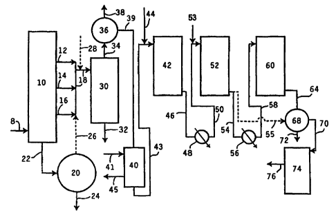
The process of the invention is fiuther illustrated by Figure 2. The
feed 8 to vacuam pipestill 10 is typically an atmospheric reduced c:ude from
an
atmospheric pipestill (not shown). Various distillate cuts shown as 12
(light), 14
(medium) and 16 (heavy) may be sent to solvent extraction unit 30 via line 18.
'These distillate cuts may range from about 200 C to about 6509C. The bottoms
from
vacunm pipestill 10 may be sent through line 22 to a coker, a visbreaker or a
deasphalting extraction unit 20 where the bottoms are contacted with a
deasphalting
solvent such as propane, butane or pentane. The deasphalted oil may be
combined
with distillate from the vacuum pipestill 10 through line 26 provided that the
deasphalted oil has a boiling point no gneater than about 650 C or is
preferably sent
on for further processing through line 24. The bottoms from deasphalter 20 can
be
sent to a visbreaker or used for asphalt production. Other refinery streams
may also
be added to the feed to the extraction unit through line 28 provided they meet
the
feedstock criteria described previously for raffinate feedstock.
CA 02319035 2006-04-28
-18-
In extraction unit 30, the distillate cuts are solvent extracted with
N-methyl pyrrolidone and the exhu-tion unit is preferably operated in
countercurrent
mode. The solvent-to-oil ratio, extraction temperature and percent water in
the
solvent are used to control the degree of extraction, i.e., separation into a
paraffins
rich raffinate and an aromatics rich exhact. The present process permits the
extrac-
tion unit to operate to an "under extraction" mode, i.e., a greater amount of
aromatics
in the paiaffins rich raffnate phase. The aromatics rich extract phase is sent
for
further processing through line 32. The raffinate phase is conducted through
line 34
to solvent stripping unit 36. Stripped solvent is sent through line 38 for
recycling
and stripped raffinate is conducted through line 39 to solvent dewaxing unit
40.
Solvent dewauing unit 40 is a oooling tower wherein chilled solvent is
added at several points along the height of the unit 40 through line 41.
Precipitated
wax is removed through line 45 while dewaxed oil is sent to first
hydroconveision
unit 42 through line 43.
TM
The first hydroconversion unit 42 contains KF-840 catalyst which is
nickel/molybd.enum on an alumina support and available from Akzo Nobel.
Hydrogen is admitted to unit or reactor 42 through line 44. Gas
chromatographic
comparisons of the hydroconverted dewaxed oil indic,ate that almost no wax
isomerization is taking place. While not wishing to be bound to any particular
theory since the precise mechanism for the VI increase which occius in this
stage is
not lcnown with certainty, it is known that heteroatoms are being removed,
aromatic
rings are being satwated and naphthene rings, particularly multi-ring
naphthenes, are
selectively eliminated.
Hydroconverted dewaxed oil from hydroconversion unit 42 is
conducted through line 46 to heat exchanger 48 where the hydroconverted
dewaxed
CA 02319035 2000-07-27
WO 99/45084 PCT/US99/03173
-19-
oil stream may be cooled if desired. The cooled hydroconverted dewaxed oil
stream
is conducted ttirough line 50 to a second hydroconversion unit 52. Additional
hydrogen, if needed, is added through line 53. This second hydroconversion
unit is
operated at a lower temperature (when required to adjust product quality) than
the
first hydroconversion unit 42. While not wishing to bound to any theory, it is
believed that the capability to operate the second unit 52 at lower
temperature shifts
the equilibrium conversion between saturated species and other unsaturated
hydro-
carbon species back towards increased saturates concentration. In this way,
the
concentration of sat<ntes can be maintained at greater than 90 wC% by
appropriately
controlling the combination of temperature and space velocity in second hydro-
conversion unit 52.
Hydroconverted dewaxed oil from unit 52 is conducted through line
54 to a second heater exchanger 56. Alteinatively, hydroconverted dewaxed oil
from unit 52 can be sent directly through line 55 to separator 68. After
additional
heat is removed through heat exchanger 56, cooled hydroconverted dewaxed oil
is
conducted through line 58 to cold hydrofinishing unit 60. Temperatures in the
hydrofinishing unit 60 are more mild than those of hydroconversion units 42
and 52.
Temperature and space velocity in cold hydro~nishing unit 60 are controlled to
reduce the toxicity to low levels, i.e., to a level sufficiently low to pass
standard
toxicity tests. This may be accomplished by reducing the concentration of poly-
nuclear aromatics to very low levels.
Hydrofinished dewaxed oil is then conducted through line 64 to
separatior 68. Light liquid products and gases are separated and removed
through
line 72. The reroaining hydrofini' shed dewaxed oil is conducted through line
70 to
catalytic dewaxing unit 74. Catalytic dewaxing involves selective
hydrocracking
with or without hydroisomerization as a means to create low pour point
lubricant
basestocks. Finished lubricant basestock is removed through line 76. If hydro-
CA 02319035 2000-07-27
WO 99/45084 PCT/US99/03173
-20-
converted raffinate from unit 52 is sent directly to separator 68 through line
55, then
basestock removed through line 76 can be sent to cold hydrofinishing (not
shown).
While not wishing to be bound by any theory, the factors affecting
saturates, VI and toxicity are discussed as follows. The tenm "saturates"
refers to the
sum of all saturated rings, paraffins and isoparaffins. In the present
raffinate hydro-
conversion process, under-extiracted (e.g., 92 Vl) light and medium raffinates
including isoparaffns, n paraffms, naphthenes and aromatics having from 1 to
about
6 rings are processed over a non-acidic catalyst which prinlarily operates to
(a)
hydrogenate aromatic rings to naphthenes and (b) convert ring compounds to
leave
isoparaffins in the lubes boiling range by either dealkylation or by ring
opening of
naphthenes. The catalyst is not an isomerization catalyst and therefore leaves
paraffinic species in the feed largely unaffected. High melting paraffins and
isoparaffins are removed by a subsequent dewaxing step. Thus other than
residual
wax the satiu ates content of a dewaxed oil product is a fimction of the
irreversible
conversion of rings to isoparaffins and the reversible formation of naphthenes
from
aromatic species.
To achieve a basestock viscosity index target, e.g., 110 VI, for a fixed
catalyst charge and feed rates, hydroconversion reactor temperature is the
primary
driver. Temperature sets the conversion (arbitrarily measured here as the
conversion
to 37(rC-) which is nearly linearly related to the VI increase, irrespective
of
pressure. This is shown in Figure 3 relating the VI increase (VI HOP) to
conversion.
For a fixed pressure, the satnrates content of the product depends on the
conversion,
i.e., the VI achieved, and the temperattnre required to achieve conversion. At
start of
run on a typical feed, the temperature required to achieve the target VI may
be only
350 C and the comesponding saturates of the dewaxed oil will normally be in
excess
of 90 wV/o, for processes operating at or above 1000 psig (7.0 mPa) H2.
However,
the catalyst deactivates with time such that the tempeiature required to
achieve the
CA 02319035 2000-07-27
WO 99/45084 PCT/US99/03173
-21-
sanae conversion (and the same VI) must be increased. Over a 2 year penod, the
temperature may increase by 25 to 50 C depending on the catalyst, feed and
the
operating pressure. A typical deactivation profile is illustrated in Figure 4
which
shows temperatare as a fimction of days on oil at a fixed pressure. In most
circumstances, with process rates of about 1.0 v/v/hr or less and temperatures
in
excess of 350 C,1he sahaates associated with the ring species left in the
product are
detezmined only by the reactor temperature, i.e., the naphthene population
reaches
the equilibrium value for that temperattnm.
Thus as the reactor temperature increases from about 350 C, saturates
will decline along a smooth curve defining a product of fixed VI. Figure 5
shows
three typical curves for a fixed product of 112 VI derived from a 92 VI feed
by
operating at a fixed conversion. Satiu-ates are higher for a higher pressure
process in
accord with simple eqnilibrium considerations. Each curve shows saturates
falling
steadily with temperatures increasing above 350 C. At 600 psig (4.24 mPa) H2,
the
process is incapable of sinmultaneously meeting the VI target and the required
saturates (90+ wt%). The projected temperatm needed to achieve 90+ wt'/o
saturates at 600 psig (4.24 mPa) is well below that which can be reasonably
achieved
with the preferred catalyst for this process at any reasonable feed
rate%atalyst
charge. However, at 1000 psig H2 and above, the catalyst can simultaneously
achieve 90 wt% satinaties and the target VI.
An impoitant aspect of the invention is ttiat a temperatnre staging
strategy can be applied to maintain saturates at 90+ wt% for process pressures
of
1000 psig (7.0 mPa) H2 or above without disengagement of sour gas and without
the
use of a polar sensitive hydrogenation catalyst such as massive nickel that is
employed in typical hydrocracking schemes. The present process also avoids the
higher tempeiatiu+es and pressures of the conventional hydrocracldng process.
This
is accomplished by separating the fimctions to achieve VI, saturates and
toxicity
CA 02319035 2000-07-27
WO 99/45084 PCT/US99/03173
-22-
using a cascading temperature profile over 3 reactors without the expensive
inserdon
of stripping, recompression and hydrogenation steps. API Group II and III base-
stocks (API Publication 1509) can be produced in a single stage, temperature
controlled process.
Toxicity of the basestock is adjusted in the cold hydrofinishing step.
For a given target VI, the toxicity may be adjusted by controlling the
temperature
and pressure. This is illushated in Figure 6 which shows that higher pressures
allows a greater teanperature range to correct toxicity.
The invention is further illusuated by the following non-limiting
examples.
EXAMPLE 1
This example summarizes fimctions of each reactor A, B and C.
Reactors A and B affect VI though A is controlling. Each reactor can
contribute to
sabuutes, but Reactors B and C ma.y be used to control satiuates. Toxicity is
controlled primarily by reactor C.
TABLE 1
Product Paratneter Reactor A Reactor B Reactor C
VI X X
Saturates X X
Toxicity x
CA 02319035 2000-07-27
WO 99/45084 PCT/US99/03173
-23-
EXAMPLE 2
This example illustrates the product quality of oils obtained from the
process according to the invention. Reaction conditions and product quality
data for
start of run (SOR) and end of nm (EOR) are swnmarized in Tables 2 and 3.
As can be seen from the data in Table 2 for the 250N feed stock,
reactors A and B operate at conditions sufficient to achieve the desired
viscosity
index, then, with adjmtnent of the temperatare of reactor C, it is possible to
keep
saturates above 90 wl'/o for the entire run length without compromising
toxicity (as
indicated by DMSO screener result; see Example 6). A combination of higher
~ and lower sps.ce velocity in reactor C (even at end of run conditions in
reactors A and B) produced even higher satiuates, 96.2%. For a 100N feed
stock,
end-of-nn product with greater tU.an 90% satUrabes may be obtained with
reactor C
operating as low as 290C at 2.5 v/v/h (Table 3).
TABLE 2
0
SOR ---- EOR ------ EOR EOR ----
Temp. LHSV Temp. LHSF Temp. LHSV Temp. LHSV
Rea~or C m m ~ v co
A 352 0.7 400 0.7 400 0.7 400 0.7
B 352 1.2 400 1.2 400 1.2 400 1.2
C 290 2.5 290 2.5 350 2.5 350 1.0
* Other Conditions: 1800 psig (12.5 mPa) H2 inlet pressure, 2400 scf/b (427
m3/m3)
Dewaxed Oil Properties 250N(1)
Feed Q F.R EOR EOR
N p
100 C Viscosity, cSt 7.34 5.81 5.53 5.47 5.62
40 C V'iscosity, cSt 54.41 34.28 31.26 30.63 32.08
Viscosity Index 93 111 115 115 114
PourPoint, C -18 -18 -16 -18 -19
Saturates, wt% 58.3 100 85.2 91 96.2
DMSO Screener for 0.30 0.02 0.06 0.10 0.04
toxicity(2)
370 C Yield, wt. on 100 87 81 81 82
raffinate feed
(1) 93 VI under extracted feed.
(2) Maximum ultra-violet absorbance at 340 to 350 nm.
Ir
CA 02319035 2000-07-27
WO 99/45084 PCT/US99/03173
-25-
TABLE 3
SOR ------- -EOR --------
Temp. LHSV Temp. LHSV
Reactor C v/v/hr C v/v/hr
A 355 0.7 394 0.7
B 355 1.2 394 1.2
C 290 2.5 290 2.5
* Other Conditions: 1800 psig (12.5 mPa) H2 inlet pressure, 2400 scf/B (427
m3/m3).
Dewaxed Oil Pro,perties 100N (1)
Feed SOR EOR
100 C Viscosity, cSt 4.35 3.91 3.83
40 C Viscosity, cSt 22.86 18.23 17.36
Viscosity Index 95 108 112
Pour Point, C -18 -18 -18
Satiuites, wC'/o 64.6 99 93.3
DMSO Screener for 0.25 0.01 0.03
toxicity (2)
370 C+ Yield, wt% on 93 80 75
raffinabe feed
(1) 95 VI under extracted feed.
(2) Iviaximum ultra-violet absorbance at 340 to 350 nm.
EXAIMPLE 3
The effect of tetnperatare and pressure on the concentration of
saturates (dewaxed oil) at constant VI is shown in this example for processing
the
under extracted 250N raffinate feed. Dewaxed product saturates equilibrium
plots
(Figure 5) were obtained at 600, 1200 and 1800 psig (4.24, 8.38 and 12.5 mPa)
H2
pressure. Process conditions were 0.7 LHSV (reactor A + B) and 1200 to 2400
SCFB (214 to 427 m3/m). Both reactors A and B were operating at the same
temperatm~e (in the range 350 to 415 C).
CA 02319035 2000-07-27
WO 99/45084 PCT/US99/03173
-26-
As can be seen from the figure it is not possible to achieve 90 wt%
sahuates at 600 psig (4.14 mPa) hydrogen partial pressure. While in ffieory,
one
could reduce the temperature to reach the 90 wt'/o target, the space velocity
would be
impractically low. The minimum pressure to achieve the 90 wt% at reasonable
space velocities is about 1000 psig (7.0 mPa). Increasing the pressure
increases the
temperature range which may be used in the first two reactors (reactor A and
B). A
practical upper limit to pressure is set by higher cost metallwgy typically
used for
hydrocrackers, which the process of the invention can avoid.
EXAMPLE 4
The catalyst deactivaxion profile as reflected by temperature required
to maintain product quality is shown in this example. Figure 4 is a typical
plot of
isothermal temperature (for reactor A, no reactor B) required to maintain a VI
-
increase of 18 points versvs time on stream. KF840 catatyst was used for
reactors A
and C. Over a two year period, reactor A tempeiazares could increase by about
50 C. This will affect the product satarates content. Strategies to offset a
decline in
product sahumtes as reactor A temperature is increased are shown below.
EXAMPLE 5
This example demonstrates the effect of temperature staging between
the first (reactor A) and second (reactor B) hydroconversion units to achieve
the
desired saturates content for a 1400 psig (9.75 mPa) HZ process with a 93 VI
raffinate feed.
CA 02319035 2000-07-27
WO 99/45084 PCT/US99/03173
-27-
TABLE 4
Base Temperature
Reactor Sequence: Case Staged Case
Rea~or T LHSV T LHSV
cci v/v/h C
A 390 0.7 390 0.7
B 390 1.2 350 0.5
C 290 2.5 290 2.5
Dewaxed Oil Viscosity 114 115
Index
Dewaxed Oil Satumates, wt% 80 96
A comparison of the base case versus the temperature staged case
demonstrates the merit of operating reactor B at lower tempecature and space
velocities. The bulk sahuates content of the product was restored to the
thermodynamic equilibrium at the temperature of reactor B.
EXAMPLE 6
The effects of temperature and pressure in the cold hydrofinishing unit
(reactor C) on toxicity are shown in this example. The toxicity is estimated
using a
dimethyl sulphoxide (DMSO) based screener test developed as a surrogate for
the
FDA (c) test. The screener and the FDA (c) test are both based on the ultra-
violet
spectrum of a DMSO extract The maximum absorbance at 345 +/- 5 nm in the
screener test was shown to correlate well with the maximum absorbance between
300-359 nm in the FDA (c) test as shown in Figure S. The upper limit of
acceptable
toxicity using the scre.ener test is 0.16 absorbance units. As shown in Figure
6,
operating at 1800 psig (12.7 Mpa) versus 1200 psig (8.38 Mpa) hydrogen parkial
pressure allows the use of a much broader temperature range (e.g., 290 to -360
C
versus a maximum of only about 315 C when operating at 1200 psig H2 (8.35
Mpa))
CA 02319035 2000-07-27
WO 99/45084 PCT/US99/03173
-28-
in the cold hydrofinisher to achieve a non-toxic product. The next example
demonstrates that higher satmmtes, non-toxic products can be made when reactor
C
is operabed at higher temperature.
EXAMPLE 7
This example is directed to the use of the cold hydrofinishing (reactor
C) unit to optimize satutates content of the oil product. Reactois A and B
were
operated at 1800 psig (12.7 mPa) hydrogen partial pressure, 2400 Scf/B (427
m3/m)
treat gas rate, 0.7 and 1.2 L.HSV respectively and at a near end-of -nm (EOR)
temperature of 400 C on a 92 VI 250N raffinate feed. The effluent from
reactors A
and B contains just 85% sahnates. Table 5 shows the conditions used in reactor
C
needed to render a product that is both higher saturates content and is non-
toxic. At
350 C, reactor C can achieve 90+'/ saturates even at space velocities of 2.5
v/v/hr.
At lower LHSV, sattuabes in excess of 95% are achieved.
TABLE 5
RUNS
Run Number 1 2 3 4
Tempe>nhue, C 290 330 350 350
LHSV, v/v/br 2.5 2.5 2.5 1.0
H2 Press, pslg 1800 1800 1800 1800
Treat Gas Rate, SCF/B 2400 2400 2400 2400
DWO VI 115 114 115 114
DWO Saturates, wt% 85 88 91 96
DMSO Screener for Toxicity(1) 0.06 0.05 0.10 0.04
(1) Maximum ultra-violet absorbance at 340-350 nm
Figure 7 further illustrates the flexible use of reactor C. As shown in
Figure 7, opti.mization of reactor C by controlling temperathm and space
velocity
gives Group II basestocks
CA 02319035 2000-07-27
WO 99/45084 PCT/US99/03173
-29-
EXAMPLE 8
This example demonstiates tllat feeds in addition to raffinates and
dewaxed oils can be upgraded to higher quality basestocks. The upgrading of
low
value foots oil streams is shown in this example. Foots oil is a waxy by
product
stream from the production of low oil content finished wax. This material can
be
used either directly or as a feed blendstock with under exftwted raffulates or
dewaxed oils. In the example below (Table 6), foots oil feeds were upgraded at
650
psig (4.58 mPa) H2 to demonstrate their value in the context of this
invention.
Reactor C was not included in the processing. Two grades of foots oil, a 500N
and
150N, were used as feeds.
TABLE 6
500 N 150N
Feed Product Feed Product
Temperahue, C (Reactor A/B) - 354 - 354
Treat Gas rate (TGR), Saf/B, (m3/m3) - 500(89) - 500 (89)
Hydrogen PartiW pressure, psig (mPa) - 650 (4.58) - 650 (4.58)
LHSV, v/v/hr (Reactor A+B) - 1.0 - 1.0
wt% 370 C - on feed 0.22 3.12 1.10 2.00
370 C+ DWO Insoections
400C viscosity, cSt 71.01 48.80 25.01 17.57
100 C viscosity, cSt 8.85 7.27 4.77 4.01
VI / Pour Point, C 97/-15 109/-17(2) 111/-8 129/-9P)
Sat rates, w't% 73.4 82.8() 79.03 88.57(1)
GCD NOACK, wt% 4.2 8.0 19.8 23.3
Dr'y Wax, ~/o 66.7 67.9 83.6 83.3
DWO Yield, wt'/o of Foots Oil Feed 33.2 31.1 16.2 15.9
Saturates improvement will be higher at higher hydrogen pressures
(2) Excellent blend stock
Table 6 shows that both a desirable basestock with significanfly higher
VI and sabuates content and a valuable wax product can be recovered from foots
oil.
CA 02319035 2000-07-27
WO 99/45084 PCT/US99/03173
-30-
In general, since wax molecules are neither consumed or fonmed in this
process,
inclusion of foots oil streams as feed blends provides a means to recover the
vaiuable
wax while improving the quality of the resultant base oil product.
EXAMPLE 9
This example illustrates the advantage of catalytic trim dewaxing a
solvent dewaxed hydrotreated raffnate. The trim catalytic dewaxed products,
even
though they have lower VI, have much better low temperature properties (
products
as defined by lower Brookfield Viscosity ) than the corresponding solvent
dewaxed
feed. Trim dewaxing refers to the process of solvent dewaxing followed by
catalytic
dewaxing.
A raffinate product made under the conditions in Table 7 was topped
at 370 C to give a 370 C+ product which was solvent dewaxed using 1VIIBK in a
3:1
solvent to raffmate product ratio and a filter temperature of -21 C to make a
dewaxed oil having the properties shown in Table 8.
TABLE 7
Process Conditions
Rl Conditi
ons
Pressure, psig 1800 (12.4 mPa)
TGR, scf/B 2500 (445 m3/m)
Space Velocity, v/v/h 0.7
Temperature, C 375
R2 Conditions
Pressute, psig 1800
TGR, scf/B 2400 (427 m3/m)
Space Velocity, v/v/h 2.5
Temperahue, C 290
CA 02319035 2000-07-27
WO 99/45084 PCT/US99/03173
-31-
TABLE 8
Product Pmperties
Viscosity, cSt at 100 C, 4.182
Viscosity, cSt at 40 C, 20.495
SUS, cP at 100 F 107.7
vi 106
Pour Point, C -19
Brookfield Viscosity, at -40 C 39900
This dewaxed oil was then catalytically dewaxed over a 0.5 wt% Pt
TON (zeolite) / Pt Silica-alumina (25:75 wdwk zeolite: silica-alumina ) mixed
powder c,omposite catalyst under the conditions shown in Table 9 and to
produce the
products, after fisctionation at 370 C, shown in Table 9.
TABLE 9
Process Conditions
Pressure, psig 1000 1000 (7.0 mPa)
TGR, scf/B 2500 2500 (445 m3/m3)
Space Velocity, v/v/h 1.0 1.0
Temperatcue, C 295 303
Yield, wt% 67 60
Product
Pro~
Viscosity, cSt at 100 C, 4.150 4.122
Viscosity, cSt at 40 C, 20.634 20.441
SUS, cP at 100 F 108.4 107.5
vi 101.7 101.3
Pour Point, C -33 -40
Brookfield Viscosity, cP at -40 C 32100 22900
The dewaxed oils, both feed and products from the catalytic dewaxer
were formulated as Automatic Transmission Fluids using a Ford type ATF ad pack
(22 wt% treat rate of ATF ad pack, 78 wt% dewaxed oil) and Brookfield
Viscosities
CA 02319035 2000-07-27
WO 99/45084 PCT/US99/03173
-32-
at -40 C measured. The Brookfield Viscosities for both feed and products are
shown in Tables 8 and 9 respectively.
EXAMPLE 10
This example illustrates the advantage of catalytic dewaxing a total
liquid product produced from hydrotreating a raffinate over the process
described in
Example 9. Catalytic dewaxing is shown to give a product with improved VI over
that obtained by solvent dewaxing at the same pour points. In addition, the
catalytic
dewaxed products have much better low temperature properties (as defined by
lower
Brookfield Viscosity ) than the corresponding solvent dewaxed product.
A hydrotreated raffinate product was made under the conditions listed
in Table 10.
TABLE 10
Process Conditions
Rl Conditions
Presmre, psig 1800 (12.4 mPa)
TGR, scf/B 2400 (427 m3/m)
Space Velocity, v/v/h 0.7
Temperature, C 382
R2 Conditions
Pressare, psig 1800
TGR, scf/B 2400
Space Velocity, v/v/h 2.5
Temperature, C 290
The hydrotreated raffinate total liquid product made under the condi-
tions in Table 10 was topped at 370 C to give a 370 C+ product which was
solvent
CA 02319035 2000-07-27
WO 99/45084 PCT/US99/03173
-33-
dewaxed using MIBK in a 3:1 solvent to raffinate product ratio and a filter
tempera
ture of -21 C. to make a dewaxed oil having the properties shown in Table 11.
TABLE 11
Product Properties
Viscosity, cSt at 100 C, 3.824
Viscosity, cSt at 40 C, 17.5
SUS, cP at 100 F 93.5
VI 109.3
Pour Point, C -19
Yield on TLP, wN/o 65.5
Brookfield Viscosity, cP at -40 C 26800
The total liquid product fiam this step was then catalytically dewaxed
over a 0.5 wt'/o Pt TON (zeolite) / Pt Silica-alumina (25:75 wr/wt
zeolite:silica-
alumina) mixed powder composite catalyst under the conditions shown in Table
12
and to produce the products, after topping at 370 C, shown in Table 11.
TABLE 12
Process Conditions
Pressm, psig 1000 1000 1000 (7.0 mPa)
TGR, scf/B 2500 2500 2500 (445 m3/m3)
Space Velocity, v/v/h 1.0 1.0 1.00
Temperature, C 304 306 314
Yield, wt% 48.2 46.3 33.5
Product Prooerties
Viscosity, cSt at 100 C 3.721 3.672 3.593
Viscosity, cSt at 40 C, 16.511 16.256 15.925
SUS, cP at 100 F 89.0 87.8 86.4
vi 112.6 111 107.0
Pour Point, C -20 -23 -39
Brookfield Viscosity, at -40 C 13640 12740 10600
CA 02319035 2000-07-27
WO 99/45084 PCT/US99/03173
-34-
The dewaxed oils, both solvent dewaxed and the products from the
catalytic dewaxer, were fonnulated as Automatic Transmission Fluids using a
Ford
type ATF ad pack (22 wt% treat rate of ATF ad pack, 78 wt% dewaxed oil) and
Brookfield Viscosities at -40 C measured. The Brookfield Viscosities for both
feed
and products are shown in Tables 5 and 6 respectively.
Figure 9 shows the benefit of catalytic dewaxing both the DWO and
total liquid products. Comparing the data in Examples 9 and 11(Tables 9 and
12)
shows a fiirther benefit for dewaxing a TLP vs. a DWO in that the fonner
results in
products having a higher VI at the same pour point Catalydc dewaxmg also
improves the VI of the products from dewaxing a TLP over that obtained by
solvent
dewaxing.
EXAMPLE 11
This example further illustrates the advantage of catalytic dewaxing a
total liquid product veisos solvent dewaxing to the same pour point Catalytic
dewaxing is shown to give a product with improved VI over that obtained by
solvent
dewaxing at the same pour points. In addition, the catalytic dewaxed products
have
much better low temperature properties (as defined by lower Brookfield
Viscosity
)
than the conesponding solvent dewaxed product
A hydrotreated raffinate product was made under the conditions listed
in Table 10.
CA 02319035 2000-07-27
WO 99/45084 PCT/US99/03173
-35-
TABLE 13
Process Conditions
Ri Conditions
Pressure, psig 1800 (12.5 mPa)
TGR, scf/B 2400 (427 m3/m)
Space Velocity, v/v/h 0.7
Temperature, C 382
R2 Conditions
Pressare, psig 1800
TGR, scf/bbl 2400
Space Velocity, v/v/h 2.5
Temperature, C 290
The hydrotreated raffinate totai liquid product made under the condi-
tions in Table 4 was topped at 370 C to give a 370 C+ product which was
solvent
dewaxed using MIBK in a 3:1 solvent to raffinate product ratio and a filter
tempera-
ture of -21 C to make a dewaxed oil having the properties shown in Table 14.
TABLE 14
Product Properties
Viscosity, cSt at 100 C, 5.811
Viscosity, cSt at 40 C, 34.383
SUS, cP at 100 F 177
vi 110.6
Pour Point, C -21
Yield on TLP, wt% 64.6
Brookfield Viscosity, cP at -40 C 148200
The total liquid product from this step was then catalytically dewaxed
over a 0.5 wt% Pt TON ( zeolite )/ Pt Silica-alumina ( 25:75 wdwt~ zeolite:
silica-
CA 02319035 2000-07-27
WO 99/45084 PCT/US99/03173
-36-
alumina ) mixed powder composite catatyst under the conditions shown in Table
15
and to produce tbe products, affter topping at 370 C, shown in Table 11.
TABLE 15
Process Conditions
Pressure, psig 1000 1000 1000 (7.0 mPa)
TGR, scf/B 2500 2500 2500 (445 m3/m)
Space Velocity, v/v/h 1.0 1.0 1.00
Temperature, C 304 306 314
Yield, wt% 48.2 46.3 33.5
Product Pr4Per~'es
Viscosity, cSt at 100 C, 5.309 5.261 5.115
Viscosity, cSt at 40 C, 28.899 28.552 27.364
SUS, cP at 100 F 148.9 147.2 141.2
VI 117.6 117.0 116.4
Pour Point, C -13 -20 -18
Brookfield Viscosity, at -40 C 47150 35650 38150
The dewaxed oils, both solvent dewaxed and the products from the
catalytic dewaxer, were formulated as Automatic Transmission Fluids using a
Ford
type ATF ad pack (22 wt% treat rate of ATF ad pack, 78 wt% dewaxed oil) and
Brookfield Viscosities at -40 C measured. The Brookfield Viscosities for both
feed
and products are shown in Tables 14 and 15 respectively.
Figure 10 is a graphical illustration of the results from Example 11.
This example also illustzates the benefit of catalytic dewaxing versus solvent
dewaxing in that the VI of the products from catalytic dewaxing are higher
than that
obtained by solvent dewaxing.