Note: Descriptions are shown in the official language in which they were submitted.
CA 02319341 2000-08-02
WO 99/39550 1 PCT/EP99/00669
Flat heating element and use of flat heating elements
The invention refers to a flat heating element, more particularly a resistance-
heating
element, and uses of flat heating elements.
Resistance-heating elements are used in different sectors to generate heat. As
a rule,
these heating elements require high voltages in the heating element in order
to
generate a sufficiently high temperature. These high voltages, however, can
constitute
safety risks, particularly when used to heat media or when in contact with the
human
1o body. Moreover, because of the materials used in them, most traditional
resistance-
heating elements are suitable only for low temperatures, particularly in 'long-
term
operation. Other proposals of the prior art require a complex constitution of
the
resistance-heating element and hence limit possible applications of the
resistance-
heating element.
It is the objective of the present invention to provide a heating element with
which a
high output per unit area and thus high temperatures can be generated even in
long-
term operation while low voltages prevail in the heating element. In addition,
the
heating element should be versatile in its applications and simple to provide
with
2o contact terminals.
The invention further refers to a heatable pipe in which a resistance-heating
element is
employed.
Pipes are extensively employed, for instance, to conduct fluid media. When
such
pipes for instance are laid underground or as open-air piping in cold regions,
the risk
exists that the medium present in the pipe solidifies because of the low
temperatures,
and the pipe clogs.
3o It is a further objective of the invention, therefore, to provide a pipe
that can be heated
by simple means and used in a versatile manner.
CA 02319341 2000-08-02
WO 99/39550 2 PCT/EP99/00669
1
The invention further relates to a heatable transportation device for media.
Media such as gases or liquids often are transported in tanks mounted on
railway cars
or on trucks. At low ambient temperatures, the medium in the tank can freeze
and thus
may even damage the tank. The installation of heating elements in such cars is
highly
demanding with respect to the heating element as well as to the heat transfer
that can
occur between the heating element and the car. Dangerous substances somtimes
are
transported in such tanks. It is important then that the heating element will
not lead to
any local temperature increase. But also a failure of the heating element, for
instance
1o as a result of its detachment from the tank, must be avoided in order to
prevent
freezing of the medium.
It is a further objective of the present invention, therefore, to provide a
transportation
device for media in which during transport a medium can be kept at a
predetermined
temperature, without creating safety risks such as freezing, an explosion or a
fire.
The invention further refers to a heat roller, particularly for its use as a
copying or
foil-coating roller.
2o In many areas of heating technology, it is necessary to provide a roller
which can be
heated to a certain temperature. Up to now such heat rollers have been
produced with
heating elements having resistance wires embedded in an insulating mass.
Another
operating mode of heat rollers, for instance in copiers, is the installation
of a halogen
emitter in the roller. Both of these versions have the disadvantage of being
either very
expensive in their manufacture or exhibiting a poor efficiency of heat
transfer.
The present invention is based on the objective to provide a heat roller of
simple
design that can be operated with low voltage and at the same time has a high
heat
transfer efficiency. The heat roller should further be versatile in its
applications.
CA 02319341 2000-08-02
WO 99/39550 3 PCT/EP99/00669
The invention is based on the realization that these objectives can be reached
by a
resistance-heating element in which the heating current flows in an optimum
way
through a suitable resistive mass.
The invention is further based on the realization that the further objectives
can be
reached in particular by a pipe, a transportation device and a heat roller
provided with
a resistance-heating element, where the resistance-heating element comprises a
suit-
able resistive mass, the heating current flows in an optimum way through this
mass,
the heating element is of flat shape and guarantees a heat transfer that is
uniform
1o across the area.
According to the invention, the objectives are reached by a flat heating
element
comprising a thin resistance layer containing an intrinsically
electroconductive poly-
mer and at least two flat electrodes arranged on one side of the resistance
layer at a
distance from each other.
In the heating element according to the invention, the resistance layer
contains an
intrinsically electroconductive polymer.
2o These polymers which, according to the invention, are used in the
resistance layer
have a constitution such that the current flows along the polymer molecules.
Owing to
the polymer structure, the heating current is conducted through the resistance
layer
along the polymers. Because of the electric resistance of the polymers, heat
is
generated which can be transferred to an object to be heated. Here the heating
current
cannot follow the shortest pathway between the two electrodes but follows the
structure of the polymer arrangement. Thus, the length of the current path is
predetermined by the polymers, so that even in the instance of small layer
thicknesses,
relatively high voltages can be applied without causing a voltage breakdown.
Even in
the instance of high currents such as making currents, one must not be afraid
of a
3o burn-out. Moreover, the distribution of the current in the first electrode
and its
subsequent conduction along the polymer structure in the resistance layer
leads to a
CA 02319341 2000-08-02
WO 99/39550 4 PCT/EP99/00669
homogeneous temperature distribution within the resistance layer. This
distribution
arises immediately after applying voltage to the electrodes.
Because of the polymers employed according to the invention, the resistance-
heating
element can be operated even at high voltages, for instance line voltage. As
the
attainable heating power increases with the square of operating voltage, the
resist-
ance-heating element according to the invention can yield high heating power
and
hence high temperatures. According to the invention, the current density is
minimized
because a relatively long current path is provided along the electroconductive
poly-
1o mers or because at least two zones electrically in series which contain the
intrinsically
electroconductive polymer used according to the invention are created.
Moreover, the electroconductive polymers used according to the invention
exhibit
long-term stability. This stability is explained above all by the fact that
the polymers
are ductile, so that a rupture of the polymer chains and thus interruption of
the current
path will not occur when the temperature is raised. The polymer chains are
unharmed
even after repeated temperature fluctuation. In conventional resistance-
heating ele-
ments, to the contrary, where conductivity is created, for instance, by carbon
black
skeletons, such a thermal expansion would lead to interruption of the current
path and
2o hence to overheating. This would lead to a strong oxidation and to burn-out
of the
resistance layer. The intrinsically electroconductive polymer used according
to the
invention is not subject to such aging phenomena.
The intrinsically conductive polymers used according to the invention resist
aging
even in reactive environments such as air oxygen. Moreover, current conduction
through the resistive mass is of the electronic conduction type. Hence even an
autodestruction of the resistance layer by electrolysis reactions caused by
electric
currents will not occur in the resistance-heating element according to the
invention. In
the resistance-heating element according to the invention, time-dependent
drops in
3o heating power per unit area are very small and approximately zero, even at
temperatures as high as 500 °C for instance, and at heating powers per
unit area as
high as 50 kW/m2 for instance.
CA 02319341 2000-08-02
WO 99/39550 5 PCT/EP99/00669
Due to the use of intrinsically electroconductive polymers, the resistance
layer as a
whole which is used according to the invention presents a homogeneous
structure that
permits a heating that is uniform across the entire layer.
According to the invention, contact to the resistance-heating element is
provided by
two electrodes which preferably consist of a material of high electric
conductivity and
are arranged on one side of the resistance layer. This type of contact
arrangement
makes it possible to use the mode of operation of the intrinsically conductive
1o polymers used according to the invention in a particularly advantageous
way. The
applied current first spreads within the first electrode, then crosses the
thickness of the
resistance layer along the polymer structure, and finally is conducted to the
second
contacted electrode. Therefore, the current path is additionally extended over
that
present in a structure where the resistance layer is sandwiched between the
two
1s electrodes. Because of this flow of the current, the thickness of the
resistance layer
can be kept small.
The heating element according to the invention has the further advantage of
being
versatile in its applications. The electrodes are provided with contacts on
one side of
2o the resistance layer. The opposite side of the resistance layer therefore
is free of
contact terminals, and hence can be of flat shape. Such a flat surface permits
a direct
application to the body to be heated. An ideal heat transfer becomes possible
since the
contact area between the resistance-heating element and the body to be heated
is not
disrupted by contact terminals.
In a preferred embodiment, a flat floating electrode is arranged on the side
of the
resistance layer opposite to the two flat electrodes.
In the spirit of the invention, an electrode is called floating when it is not
connected to
the source of current. It can have an insulation preventing electric contact
with a
source of current.
CA 02319341 2000-08-02
WO 99/39550 6 PCT/EP99/00669
This floating electrode supports the flow of current through the resistance
layer. In
this embodiment the current spreads within the first electrode, crosses the
thickness of
the resistance layer to reach the floating electrode on the opposite side, is
conducted
further within this electrode, and finally flows through the thickness of the
resistance
layer to the other electrode that is arranged on the same side of the
resistance layer as
the first electrode.
In this embodiment of the heating element, the current flows through the
thickness of
the resistance layer, essentially in a direction normal to its surface.
Essentially two
to zones develop within the resistance layer. Within the first zone, the
current flows
essentially vertically from the first contacted electrode to the floating
electrode, while
within the second zone, it flows essentially vertically from the floating
electrode to
the second contacted electrode. Thus, a series arrangement of several
resistances is
attained by this arrangement. This effect implies that the partial voltage
prevailing in
the individual zones is smaller than the applied voltage. Thus, in this
embodiment of
the invention the voltage prevailing in the individual zones is half of the
applied
voltage. Because of the low voltage prevailing in the resistance layer, safety
risks can
be avoided with the heating element according to the invention, and possible
app-
lications thus are manifold. The heating element can then also be used in
devices
2o where it comes in immediate contact with a medium to be heated, or must be
touched
by the persons which operate or use the device.
Moreover, the gap provided between the contacted electrodes acts as an
additional
resistance arranged in parallel. With air as the insulator in this gap, the
resistance will
be determined by the mutual distance of the electrodes and thus by the surface
resistance of the resistance layer.
The electrodes and the floating electrode preferably have a good thermal
conductivity.
This can exceed 200 W/m~K, preferably 250 W/m~K. Local overheating can rapidly
3o be neutralized by this good thermal conductivity in the electrodes. An
overheating is
thus possible only in the direction of layer thickness, but has no negative
effects
because of the small layer thickness that can be realized in the resistance-
heating
CA 02319341 2000-08-02
WO 99/39550 7 PCT/EP99/00669
element according to the invention. It is a further advantage of the
resistance-heating
element that even a local temperature increase provoked from outside, e.g.,
from the
body to be heated, can be balanced in an ideal way by the resistance-heating
element.
The electrodes and the floating electrode are preferably made of a material
having a
high electric conductivity. Thus, the specific electric resistance of the
electrodes may
be less than 10~ S2~cm, and preferably less than 105 S2~cm. Suitable materials
are
aluminum and copper, for instance. By selecting such an electrode material it
is
guaranteed that the current applied is conducted further within the flat
electrode, i.e.,
1o spreads within it, before passing through the resistance layer. This leads
to a uniform
flow of the heating current through the resistance layer and thus a uniform
and
essentially complete heating of the resistance layer. Such a resistance-
heating element
therefore is able to generate and transfer heat in a uniform way. By selecting
such an
electrode material it is possible in particular to fabricate large resistance-
heating
elements without a need for voltage supply to a number of spots along the
length or
width of the electrodes. Therefore, power supply lines need not be installed
along the
surface. According to the invention, such multiple contacts will only be
selected for
embodiments in which the resistance-heating element covers a large area or
length,
for instance areas larger than 60 cm2, preferably larger than 80 cm2. The
limiting size
of the resistance-heating element above which it becomes meaningful to provide
multiple contact points depends, not only on the electrode material selected,
but also
on the place of the contacts. Thus, multiple contact points may not be
required even
for areas larger than those mentioned above when the electrode is accessible
in its
surface midpoint and can be provided with a contact there.
The size of the resistance-heating element that can be operated with single
contacts
also depends on the thickness of the electrodes selected. According to one
ernbodi-
ment, the electrodes and the floating electrodes have a thickness of 50 to 150
~,m,
preferably 75 to 100 ~,m each. These small layer thicknesses are also
advantageous in
3o that the heat produced by the resistance-heating element can readily be
transferred
from them. Moreover, thin electrodes are more flexible, so that a detachment
of the
CA 02319341 2000-08-02
WO 99/39550 8 PCT/EP99/00669
electrodes from the resistance layer and thus an interruption of the
electrical contact
during thermal expansion of the resistance layer will be avoided.
According to the invention, the resistance layer is thin. Its thickness has a
lower limit
that merely depends on the breakdown voltage, and is preferably 0.1 to 2 mm,
pre-
ferably 1 mm. A small layer thickness of the resistance layer offers the
advantage of
enabling a short heat-up time, rapid heat transfer and high heating power per
unit area.
However, such a layer thickness is only possible with a resistance-heating
element
according to the invention. On one hand, the current path within the
resistance layer is
1o predetermined by the polymers used according to the invention, and can be
sufficiently long to prevent voltage breakdown, even when the layer
thicknesses are
small. On the other hand, the unilateral contact arrangement of the resistance-
heating
element permits subdivision of the resistance layer into zones of lower
voltage, which
additionally reduces the risk of breakdown.
The advantages of the resistance-heating element according to the invention
are
further enhanced when the resistance layer has a positive temperature
coefficient
(PTC} of its electric resistance. This leads to an effect of automatic
regulation with
respect to the highest attainable temperature. This effect occurs, since the
flow of
2o current through the resistive mass is adjusted as a function of temperature
because of
the PTC of the resistance layer. The current becomes lower the higher the
temperature, until at a particular thermal equilibrium it has become
immeasurably
small. A local overheating and melting of the resistive mass can therefore be
prevented reliably. This effect of automatic regulation is very important for
the
heating element according to the invention, since a local temperature rise may
occur,
for instance, when the heating element according to the invention has
insufficient
contact with a body to be heated, and hence a low heat transfer.
Selecting a PTC material for the resistance layer also implies, therefore,
that as a
3o result, the entire resistance layer is heated to essentially the same
temperature. This
enables uniform heat transfer, which can be essential for particular
applications of the
resistance-heating element.
CA 02319341 2000-08-02
WO 99/39550 9 PCT/EP99/00669
According to the invention, the resistance layer can be metallized on its
surfaces
facing the electrodes and, if present, the floating electrode. By
metallization, metal
adheres to the surface of the resistance layer and thus improves the flow of
current
between the electrodes or the floating electrode and the resistance layer.
Moreover, in
this embodiment the heat transfer from the resistance layer to the floating
electrode
and hence to the body or object to be heated is also improved. The surface can
be
metallized by spraying of metal. Such a metallization is possible only with
the
material of the resistance layer that is used according to the invention. A
costly
1o metallization step, for instance by metal electroplating, hence is
superfluous and
considerably reduces the manufacturing cbsts.
The intrinsically electroconductive polymer is preferably produced by doping
of a
polymer. The doping can be a metal or semimetal doping. In these polymers the
defect carrier is chemically bound to the polymer chain and generates a
defect. The
doping atoms and the matrix molecule form a so-called charge-transfer complex.
During doping, electrons from filled bands of the polymer are transferred to
the
dopant. On account of the electronic holes thus generated, the polymer takes
on
semiconductor-like electrical properties. In this embodiment, a metal or
semimetal
2o atom is incorporated into or attached to the polymer structure by chemical
reaction in
such a way that free charges are generated which enable the flow of current
along the
polymer structure. The free charges are present in the form of free electrons
or holes.
In this way an electronic conductor arises.
Preferably, for its doping the polymer was mixed with such an amount of dopant
that
the ratio of atoms of the dopant to the number of polymer molecules is at
least 1:1,
preferably between 2:1 and 10:1. With this ratio it is achieved that
essentially all
polymer molecules are doped with at least one atom of the dopant. The
conductance
of the polymers and hence that of the resistance layer as well as the
temperature
coefficient of resistance of the resistance layer can be adjusted by selecting
the ratio.
CA 02319341 2000-08-02
WO 99/39550 10 PCT/EP99/00669
The intrinsically electroconductive polymer used according to the invention
can be
employed as material for the resistance layer in the resistance-heating
element
according to the invention, even without graphite addition, but according to a
further
embodiment, the resistance layer may additionally contain graphite particles.
These
s particles can contribute to the conductivity of the complete resistance
layer, are
preferably not in mutual contact, and in particular do not form a reticular or
skeletal
structure. The graphite particles are not solidly bound into the polymer
structure but
are freely mobile. When a graphite particle is in contact with two polymer
molecules,
the current can jump via the graphite from one chain to the next. The
conductivity of
1 o the resistance layer can be further raised in this way. On account of
their free mobility
in the resistance layer, the graphite particles can also move to the surface
of this layer
and bring about an improvement of its contact with the electrodes or with the
floating
electrode.
15 The graphite particles are preferably present in an amount of at most 20
vol.%, and
particularly preferably in an amount of at most 5 vol.% relative to the total
volume of
the resistance layer, and have a mean diameter of at most 0.1 Vim. With this
small
amount of graphite and the small diameter, formation of a graphite network
which
would lead to current conduction through these networks can be avoided. It is
thus
2o guaranteed that the current essentially continues to flow by electronic
conduction via
the polymer molecules, and thus the advantages mentioned above can be
attained. In
particular, conduction need not be along a graphite network or skeleton where
the
graphite particles must be in mutual contact, and which is readily destroyed
under
mechanical and thermal stress, but it rather occurs along the ductile and
aging-
25 resistant polymer.
Both electroconductive polymerizates such as polystyrene, polyvinyl resins,
polyacrylic acid derivatives and mixed polymerizates of these, and
electroconductive
polyamides and their derivatives, polyfluorinated hydrocarbons, epoxy resins
and
3o polyurethanes can be used as intrinsically electroconductive polymers.
Polyamides,
polymethyl methacrylates, epoxides, polyurethanes as well as polystyrene or
their
mixtures can preferably be used. Polyamides additionally exhibit good adhesive
CA 02319341 2000-08-02
WO 99/39550 11 PCT/EP99/00669
properties, which are advantageous for the preparation of the resistance-
heating
element according to the invention. Some polymers, for instance
polyacetylenes, are
eliminated from uses according to the invention because of their low aging
resistance
due to reactivity with oxygen.
The length of the polymer molecules used varies within wide ranges, depending
on
the type and structure of the polymer, but is preferably at least 500 and
particularly
preferably at least 4000 t~.
to In one embodiment, the resistance layer has a support material. This
support material
on one hand can serve as Garner material for the intrinsically conductive
polymer, on
the other hand it functions as a spacer, particularly between the electrodes
and the
floating electrode. The support material in addition confers some rigidity on
the
resistance-heating element, so that this will be able to resist mechanical
stress.
Moreover, when using a support material one can precisely adjust the layer
thickness
of the resistance layer. Glass spheres, glass fibers, rock wool, ceramics such
as barium
titanate or plastics can serve as support materials. A support material
present as a
tissue or mat, for instance of glass fibers, can be immersed into a mass
consisting of
the intrinsically electroconductive polymer, i.e., can be impregnated with the
2o intrinsically electroconductive polymer. The layer thickness then is
determined by the
thickness of the grid or mat. Methods such as scraping, spreading or known
screen-
printing methods can also be used.
Preferably, the support material is a flat porous, electrically insulating
material. With
such a material it can in addition be prevented that the heating current flows
through
the support material rather than through the polymer structure.
The possibility of producing layers which across their surface deviate from
the desired
layer thickness with minimum tolerances, for instance 1 %, is of particular
signifi-
3o cance, especially with the small layer thicknesses used according to the
invention,
since otherwise one would have to be afraid of a direct contact between
contacted
electrode and floating electrode. Fluctuations in layer thickness across the
layer
CA 02319341 2000-08-02
WO 99/39550 12 PCT/EP99/00669
surface can also influence the temperature generated, and lead to a nonuniform
temperature distribution.
The support material has the further effect that the current cannot flow along
the
shortest path between the electrodes and the floating electrode but is
deflected or split
up at the filler material. Thus an optimum utilization of the energy supplied
is
achieved.
The object of the invention is explained in the following with the aid of the
1o accompying drawings.
It is shown:
in figure 1 a partial sectional view of one embodiment of the heating element
according to the invention;
in figure 2 a schematic lateral view of an embodiment with several floating
electrodes;
in figure 3 a diagrammatic sketch of the zones developing in an embodiment
2o according to figure 2.
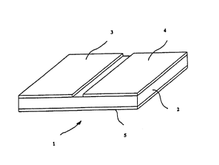
The heating element 1 has a thin resistance layer 2 and two flat electrodes 3
and 4
arranged side by side at a distance from each other and covering essentially
all of the
resistance layer. On the opposite side of the resistance layer 2 a floating
electrode 5 is
arranged which covers the resistance layer over the full area formed by the
electrodes
3 and 4 as well as by the gap between these electrodes. When the electrodes 3
and 4
are brought in contact with a source of current (not shown), the current will
first
spread within electrode 3, then flows through the resistance layer 2,
essentially in a
direction normal to its surface facing the floating electrode 5, is conducted
further
3o within this electrode, flows through the resistance layer 2 to the
electrode 4 and is
drained from there. Depending on the contact arrangement at electrodes 3 and
4, the
CA 02319341 2000-08-02
WO 99/39550 13 PCT/EP99/00669
current may also flow in the opposite direction. In the embodiment
represented, the
insulation between electrodes 3 and 4 is formed by an air gap.
In figure 2, a heating element is shown which has a thin resistance layer 2.
On one
side of the resistance layer 2, two flat electrodes 3 and 4 as well as several
inter-
mediate floating electrodes 5 are provided. Electrodes 3 and 4 and the
floating elec-
trodes S are at distances from each other and offset relative to the floating
electrodes 5
arranged on the opposite side of the resistance layer 2. In this arrangement,
the current
applied to electrodes 3 and 4 flows through the resistance layer 2 and
floating
1 o electrodes 5 in the direction indicated by arrows in the drawing. With
this current
flow, resistance layer 2 serves as a series arrangement of a number of
electric
resistances, which makes it possible to attain high power while in the
individual
sectors or zones of the resistance layer a low voltage prevails. Here, both
the
resistance residing in the thickness of the resistance layer 2 and the surface
resistance
in the gaps between the floating electrodes 5 or floating electrode 5 and the
electrode
3 or 4 is utilized. The large distance in space between the contacted
electrodes
moreover offers the advantage that an immediate contact between them can be
avoided.
2o Figure 3 shows a diagrammatic sketch which will be used to explain the
electro-
technical dimensions of an embodiment of the resistance-heating element
according to
the invention. Starting from the heating power per unit area of the full
resistance-
heating element which is desired in a particular case, one first determines
the number
of heating zones required across the width of the resistance-heating element
from the
ratio between the overall voltage to be applied to the contacted electrodes
and the
unique, maximum partial voltage applied to the individual partial zones which
always
are arranged in series. The length of the heating zone is designated as S, the
width Z
of the individual zones itself is calculated with the following formula:
3o Z = [B - n~A/2 - 2~K]/n
where
B = total width of the flat heating element (mm)
CA 02319341 2000-08-02
. WO 99/39550 14 PCT/EP99/00669
A = distance between the floating electrodes or floating electrode and the
electrode on one side of the resistance layer (mm)
K = width of the lateral band (mm)
n = number of individual heating zones arranged in series
to Die width of the individual electrodes or floating electrodes which are
arranged in
alternation on either surface of the resistance layer can be found from the
sum of two
zone widths and the distance A between the electrodes arranged on one side of
the
resistance layer.
The heating power Nz of an individual zone of the resistance-heating element
can be
found from:
Nz - Uz.Ic = Uzz.L = Uzz.S.Z/P.D
where
U = the maximum permitted electric zone voltage applied to the partial
resistance because of the electrical insulation (breakdown resistance) of
the resistance-heating layer required in an individual application (V)
I = current, which because of the series arrangement is constant in all
partial
resistances, and equal to the total current (A)
L = electric conductance of the intrinsically conductive polymer resistance
layer (S)
p = specific resistance of the polymer layer (S2~cm)
S = length of the electrode of the resistance-heating element (mm)
Z = width of the individual heating zones (mm)
D = thickness of the resistance layer (mm)
Both the electrodes and the floating electrode in the heating element
according to the
invention can for instance consist of metal foil or metal sheet. Moreover, the
CA 02319341 2000-08-02
WO 99/39550 15 PCTIEP99/00669
electroconductive layer can be coated with black plastic on the side facing
away from
the resistance layer. With this additional layer, the heating element
according to the
invention can assume the function of a black body and generate a penetration
effect of
the radiation generated.
In the heating element according to the invention, a multitude of electrodes
can be
provided on one side of the resistance layer. When providing a number of
electrodes
separated from each other by insulation, arranged next to each other and
functioning
as electrode pairs to which a voltage can be applied, one can achieve a
heating-up of
1 o the heating element zone by zone.
It is also within the scope of the invention to realize the insulation between
the
electrodes with an insulating material introduced into the gap between the
electrodes.
Conventional dielectrics and particularly so plastics can be used as the
insulating
material.
In the event that no voltage should be present at the surface of the heating
element
that is facing the body to be heated, one can laminate the resistance layer or
the
floating electrode with polyester, PTFE, polyimide and other foils. The use of
these
2o conventional insulating materials and of a simple form such as a foil
becomes possible
in the heating element according to the invention because the floating
electrode is free
of contact terminals and hence has a smooth surface.
The resistance layer can have a structure in which different resistive
materials with
different specific electric resistances are present in the form of layers.
This embodiment has the advantage that by suitable selection of the materials
in the
resistance layer, the side of the resistance layer from which heat is to be
transferred to
the body to be heated, can have higher temperatures, while it is not necessary
that
different heating currents are separately conducted, for instance with heating
wires, in
individual layers of the resistance layer. This is achieved when the specific
electric
resistance of the polymer employed is selected so as to increase from the
layer that is
CA 02319341 2000-08-02
WO 99/39550 16 PCT/EP99/00669
adjacent to the electrodes, in a direction to the side facing the body or
object to be
heated.
Because of the resistance layer and contact arrangement employed, the
resistance-
heating element according to the invention can be operated, both with low
voltages of
for instance 24 V and with very high voltages of for instance 240, 400 and up
to
1000 V.
With the resistance-heating element according to the invention, heating powers
per
to unit area in excess of 10 kW/m2 and preferably in excess of 30 kW/m2 can be
achieved. With the heating element, heating powers of up to 60 kW/m2 can be
achieved. Such a heating power of up to 60 kW/m2 can even be achieved with a
layer
thickness of the resistance layer of 1 mm. The time-dependent drop in heating
power
can be smaller than 0.01 % per year when a voltage of 240 V is continuously
applied.
The temperature that can be achieved with the resistance-heating element is
limited by
the thermal properties of the polymer selected, but can be higher than 240
°C and up
to 500 °C. The polymer should in particular be so selected that even at
the
temperatures to be achieved, conduction continues to be electronic.
The heating element can have the most diverse shapes when using the resistance
layer
that is employed according to the invention. The resistance-heating element
can have
the shape of tape with a length larger than the width where the electrodes are
strips
which extend over the full length of the tape and in the direction of the
width of the
resistance-heating element are arranged side by side. Square shapes are also
possible
with the heating element according to the invention.
The resistance-heating element can for instance be mounted on the inside or
outside of
a pipe. Here the unilateral contact arrangement of the heating element is a
particular
3o advantage, since heat transfer from the resistance-heating element to the
body to be
heated, such as a pipe, is not hindered by contact terminals. The electrical
insulation
CA 02319341 2000-08-02
WO 99/39550 17 PCT/EP99l00669
between the body to be heated and the resistance-heating element is also
simplified by
the lack of contact points on the electroconductive layer.
Within the scope of the invention, the intrinsically electroconductive polymer
can also
be selected so that over some range of temperatures it has a negative
temperature
coefficient of electric resistance. Thus, the temperature coefficient can
become
positive above a particular temperature, e.g., 80 °C.
The further objective of the invention is reached by a heatable pipe, where an
inner
to pipe is coated on its outside at least in part, directly or via an
interlayer, with a thin
resistalice layer containing an intrinsically electroconductive polymer, and
where on
the outer surface of the resistance layer at least two flat electrodes which
cover the
resistance layer at least in part are arranged at a distance from each other.
In the pipe according to the invention, the resistance layer contains an
intrinsically
electroconductive polymer. These polymers which, according to the invention,
are
used in the resistance layer have a constitution such that the current flows
along the
polymer molecules. Owing to the polymer structure, the heating current is
conducted
through the resistance layer along the polymers. Because of the electric
resistance of
2o the polymers, heat is generated which can be transferred to the inner pipe
to be heated.
Here the heating current cannot follow the shortest pathway between the two
electrodes but follows the structure of the polymer arrangement. Thus, the
length of
the current path is predetermined by the polymers, so that even in the
instance of
small layer thicknesses, relatively high voltages can be applied without
causing a
voltage breakdown. Even in the instance of high currents such as making
currents, one
must not be afraid of a burn-out. Moreover, the distribution of the current in
the first
electrode and its subsequent conduction along the polymer structure in the
resistance
layer leads to a homogeneous temperature distribution within the resistance
layer.
This distribution arises immediately after applying voltage to the electrodes.
Because of the polymers employed according to the invention, the pipe can be
operated even at high voltages, for instance line voltage. As the attainable
heating
CA 02319341 2000-08-02
WO 99/39550 18 PCT/EP99/00669
power increases with the square of operating voltage, the resistance-heating
element
according to the invention can yield high heating power and hence high
temperatures.
According to the invention, the current density is minimized because a
relatively long
current path is provided along the electroconductive polymers or because at
least two
zones electrically in series which contain the intrinsically electroconductive
polymer
used according to the invention are created.
Moreover, the electroconductive polymers used according to the invention
exhibit
long-term stability. This stability is explained above all by the fact that
the polymers
1o are ductile, so that a rupture of the polymer chains and thus interruption
of the current
path will not occur when the temperature is raised. The polymer chains' are
unharmed
even after repeated temperature fluctuation. In conventional resistance-
heating
elements, to the contrary, where conductivity is created, for instance, by
carbon black
skeletons, such a thermal expansion would lead to interruption of the current
path and
hence to overheating. This would lead to a strong oxidation and to burn-out of
the
resistance layer. The intrinsically electroconductive polymer used according
to the
invention is not subject to such aging phenomena.
The intrinsically conductive polymers used according to the invention resist
aging
2o even in reactive environments such as air oxygen. Moreover, current
conduction
through the resistive mass used according to the invention is of the
electronic
conduction type. Hence even an autodestruction of the resistance layer by
electrolysis
reactions caused by electric currents will not occur in the resistance-heating
element
according to the invention. In the resistance-heating element according to the
invention, time-dependent drops in heating power per unit area are very small
and
approximately zero, even at temperatures as high as 500 °C for
instance, and at
heating powers per unit area as high as 50 kW/m2 for instance.
This long-term stability or aging resistance is of particular significance for
the pipe
3o according to the invention, since heatable pipes are used for instance
underground or
in other places not readily accessible, so that frequent repairs are
undesirable if not
impossible.
CA 02319341 2000-08-02
WO 99/39550 19 PCT/EP99/00669
Due to the use of intrinsically electroconductive polymers, the resistance
layer as a
whole which is used according to the invention presents a homogeneous
structure that
permits a heating that is uniform across the entire layer.
s
According to the invention, contact to the pipe is provided by two electrodes
which
preferably consist of a material of high electric conductivity and are
arranged on one
side of the resistance layer. This type of contact arrangement makes it
possible to use
the mode of operation of the intrinsically conductive polymers used according
to the
invention in a particularly advantageous way. The applied current first
spreads within
the first electrode, then crosses the thickness of the resistance layer along
the polymer
structure, and finally is conducted to the second contacted electrode.
Therefore, the
current path is additionally extended over that present in a structure where
the
resistance layer is sandwiched between the two electrodes. Because of this
flow of the
current, the thickness of the resistance layer can be kept small.
The pipe according to the invention has the further advantage of being
versatile in its
applications. The electrodes are provided with contacts on one side of the
resistance
layer. This faces away from the inner pipe and hence is readily accessible for
making
connections. The opposite side of the resistance layer facing the inner pipe
therefore is
free of contact terminals, and hence can be of flat shape. This flat surface
permits a
direct application of the resistance layer to the inner pipe. An ideal heat
transfer to the
inner pipe becomes possible since the contact area between the resistance-
heating
element and the inner pipe to be heated is not disrupted by contact terminals.
With this structure according to the invention, pipes are easy to heat. The
inner pipe
can be provided with the resistance layer and the electrodes, and if required
with the
interlayer, already at the place of manufacture and incorporated into the
pipeline on
the spot in this finished state.
CA 02319341 2000-08-02
WO 99/39550 20 PCT/EP99/00669
In an embodiment of the pipe according to the invention, this pipe has an
interlayer
made of a material having a high electric conductivity between the inner pipe
and the
resistance layer.
Here the interlayer serves as floating electrode. In the spirit of the
invention, an
electrode is called floating when it is not connected to the source of
current. It can
have an insulation preventing electric contact with a source of current.
This floating electrode supports the flow of current through the resistance
layer. In
1o this embodiment the current spreads within the first electrode, crosses the
thickness of
the resistance layer to reach the floating electrode on the opposite side, is
conducted
further within this electrode, and finally flows through the thickness of the
resistance
layer to the other electrode that is found on the side of the resistance layer
facing
away from the pipe. The interlayer can be insulated from the inner pipe by
foils. The
insulation of the interlayer, which is not provided with contacts, can occur
with
known foils consisting of polyimide, polyester and silicone rubber.
In this embodiment of the heatable pipe, the current flows through the
thickness of the
resistance layer, essentially in a direction normal to its surface.
Essentially two zones
develop within the resistance layer. Within the first zone, the current flows
essentially
vertically from the first contacted electrode to the floating electrode, while
within the
second zone, it flows essentially vertically from the floating electrode to
the second
contacted electrode. Thus, a series arrangement of several resistances is
attained by
this arrangement. This effect implies that the partial voltage prevailing in
the
individual zones is smaller than the applied voltage. Thus, in this embodiment
of the
invention the voltage prevailing in the individual zones is half of the
applied voltage.
Because of the low voltage prevailing in the resistance layer, safety risks
can be
reliably avoided with the pipe according to the invention, and possible
applications
thus are manifold. Thus, the pipe according to the invention can be employed
in wet
3o areas or moist ground or find applications where people must touch the
pipe.
CA 02319341 2000-08-02
, WO 99/39550 21 PCT/EP99/00669
Moreover, the gap provided between the contacted electrodes acts as an
additional
resistance arranged in parallel. With air as the insulator in this gap, the
resistance will
be determined by the mutual distance of the electrodes and thus by the surface
resistance of the resistance layer. The distance is preferably larger than the
thickness
of the resistance layer, for instance twice the thickness of the resistance
layer.
The electrodes and the floating electrode preferably have a good thermal
conductivity.
This can exceed 200 W/m~K, preferably 250 W/m~K. Local overheating can rapidly
be neutralized by this good thermal conductivity in the electrodes. An
overheating is
to thus possible only in the direction of layer thickness, but has no negative
effects
because of the small layer thickness that cari be realized in the pipe
according to the
invention. It is a further advantage of the pipe that even a local temperature
increase
provoked from inside, e.g., from the inner pipe to be heated, can be balanced
in an
ideal way by the resistance-heating element. Such an increase in temperature
can
occur for instance in pipes only partly filled, since in zones that are filled
with air, less
heat is transferred from the pipe to the air.
The heatable pipe has the further advantage that the resistance layer arranged
on the
inner pipe can withstand even high stresses without giving rise to a local
temperature
2o rise. As a rule, the mechanical stress acting on a laid pipe, particularly
one laid
underground, is directed radially. This is the direction of current flow in
the resistance
layer of the resistance-heating element. Such a stress will therefore not lead
to an
increase in resistance in places where pressure is exerted, contrary to
resistance-
heating elements where the current would flow in a direction normal to the
compressive load.
In a fiuther embodiment of the heatable pipe according to the invention, the
resistance
layer is arranged directly on the inner pipe, which consists of an
electroconductive
material.
In this embodiment, the flow of current from one electrode to the next is
directed via
the resistive mass and the inner pipe. In view of the low voltages prevailing
in the
CA 02319341 2000-08-02
, WO 99/39550 22 PCT/EP99/00669
resistance layer of the pipe according to the invention, the inner pipe which
here
functions as a floating electrode can be adduced without safety risks as a
current
conductor. In this embodiment, the heat generated can at the same time readily
be
transferred to the medium present in the pipe. In this version, the inner pipe
can be
covered with the resistance layer over its entire periphery, and the
electrodes can
cover this layer essentially completely. However, the gap between the
electrodes that
must be provided for electrical reasons is present as well in this embodiment.
According to a further embodiment, the resistance layer and the electrodes
arranged
on this layer extend longitudinally in an axial direction, and the electrodes
are
' arranged on the resistance layer at distances from each other in the
direction of the
circumference.
In view of the longitudinal extension of the resistance layer and the
electrodes, a
certain length of pipe can be heated while the current supply is needed only
in a single
point of each of the two electrodes.
In a preferred embodiment, the resistance layer covers only part of the
periphery of
2o the inner pipe and extends longitudinally in am axial direction.
Preferably, the length
of the resistance layer and electrodes corresponds to that of the pipe.
In this embodiment, heat can be transferred to the pipe within a definite
region where
the resistance layer or, if present, the interlayer is applied to the inner
pipe. In the case
of pipes with an inner pipe having good thermal conductivity, the heat
transferred
from the resistance layer is distributed over the full periphery of the inner
pipe and
thus can heat the medium present in the pipe to the full extent. This
structure thus
provides good heating of the medium while requiring little engineering effort.
However, this embodiment is only possible when the heatable pipe has a
structure
according to the invention. Only such a structure makes it possible to achieve
high
power per unit area while avoiding any damage to the resistance layer during
CA 02319341 2000-08-02
WO 99/39550 23 PCT/EP99/00669
extended operation and under the influence of reactive substances such as
water or air
oxygen.
The resistance layer preferably covers a part of the periphery which, when the
pipe
has been laid, is situated on the lower side of the pipe. This guarantees that
even in a
pipe not completely filled, the medium to be heated is in contact with this
partial zone
and thus is heated reliably and rapidly.
In the pipe according to the invention, the electrodes and the interlayer
preferably
to consist of a material with a specific electric resistance of less than 10~
S2~cm,
preferably of less than 10-5 SZ~cm. Suitable materials are aluminum and
copper, for
instance. This is of particular significance in the pipe according to the
invention. As a
rule, pipes are used to build pipelines. It will be advantageous when the
electrical
resistance of the electrodes is low, since in such a pipeline consisting of
pipes
according to the invention, the resistance layer and the electrodes are very
long. With
such an electrode material one can avoid a voltage drop across the electrode
surface
which would lead to an overall decrease in power. Moreover, the conductivity
guarantees a rapid distribution of the current within the electrode, which
permits a
rapid and uniform heating-up of essentially the entire resistance layer and
thus the
length of the pipe while it is not necessary to apply voltage to the
electrodes in several
points along their length or width. It may then not be necessary to arrange
power
supply lines along the pipe. Such pipes can have a length of up to 1 m.
According to
the invention, such an arrangement with multiple contact points is only
selected in
embodiments where the pipe is longer. The limiting length above which a
multiple
contact arrangement will be meaningful depends, both on the electrode material
selected and on the place of the contacts. Thus, multiple contact points may
be
unnecessary even for lengths more important than those mentioned above when
the
electrodes are accessible in the midpoint of their length, and a contact can
be provided
at that point.
The length of the pipe that can be operated with single contacts also depends
on the
thickness of the electrodes selected. According to one embodiment, the
electrodes and
CA 02319341 2000-08-02
WO 99/39550 24 PCT/EP99/00669
the interlayer each have a thickness in the range of SO to 150 Vim, preferably
75 to 100
~m each. These small layer thicknesses are also advantageous in that the heat
pro-
duced by the resistance-heating element can readily be transferred from the
interlayer
to the pipe. Moreover, thin electrodes are more flexible, so that a detachment
of the
electrodes from the resistance layer and thus an interruption of the
electrical contact
during thermal expansion of the resistance layer will be avoided.
In pipelines of great length, a multiple contact arrangement may yet be
necessary.
With the pipe according to the invention, however, this is readily provided.
The
1 o electrodes are only provided with contact terminals from the outside, so
that these are
readily accessible. Thus, a power line extending along the pipe and connecting
the
electrodes at intervals to the voltage source can be provided along the
pipeline. 'This
makes it possible to operate long pipes according to the invention.
According to the invention, the resistance layer is thin. Its thickness has a
lower limit
that merely depends on the breakdown voltage, and is preferably 0.1 to 2 mm,
preferably 1 mm. A small layer thickness of the resistance layer offers the
advantage
of enabling a short heat-up time, rapid heat transfer and high heating power
per unit
area. However, such a layer thickness is only possible with the intrinsically
con-
2o ductive polymer and contact arrangement used. On one hand, the current path
within
the resistance layer is predetermined by the polymers used according to the
invention,
and can be sufficiently long to prevent voltage breakdown, even when the layer
thicknesses are small. On the other hand, the unilateral contact arrangement
permits
subdivision of the resistance layer into zones with lower voltage, which
additionally
reduces- the risk of breakdown.
The advantages of the pipe according to the invention are further enhanced
when the
resistance layer has a positive temperature coefficient (PTC) of its electric
resistance.
This leads to an effect of automatic regulation with respect to the highest
attainable
3o temperature. Overheating of the pipe and and reactions in the pipe caused
by this
overheating can be avoided by this effect. This effect occurs, since the flow
of current
through the resistive mass is adjusted as a function of temperature because of
the PTC
CA 02319341 2000-08-02
x WO 99/39550 25 PCT/EP99/00669
of the resistance layer. The current becomes lower the higher the temperature,
until at
a particular thermal equilibrium it has become immeasurably small. A local
over-
heating and melting of the resistive mass can therefore be prevented reliably.
This
effect is of particular significance in the present invention. If for instance
the pipe is
only half filled with a liquid medium, heat is more readily withdrawn from
this region
of the pipe than from the region of the pipe where the pipe is air-filled. A
con-
ventional resistance-heating element would heat up and perhaps melt because of
deficient heat withdrawal. In the heatable pipe according to the invention,
this melting
is avoided by the effect of automatic regulation.
to
Selecting a PTC material for the resistance layer also implies, therefore,
that as 'a
result, the entire resistance layer is heated to essentially the same
temperature. This
enables uniform heat transfer, which can be essential for particular
applications of the
pipe, for instance when heat-sensitive media are conveyed through the pipe.
According to the invention, the resistance layer can be metallized on its
surfaces
facing the electrodes and the interlayer. By metallization, metal adheres to
the surface
of the resistance layer and thus improves the flow of current between the
electrodes or
the floating electrode and the resistance layer. Moreover, in this embodiment
the heat
2o transfer from the resistance layer to the floating electrode and hence to
the inner pipe
to be heated is also improved. The surface can be metallized by spraying of
metal.
Such a metallization is possible only with the material of the resistance
layer that is
used according to the invention. A costly metallization step, for instance by
metal
electroplating, hence is superfluous and considerably reduces the
manufacturing costs.
The intrinsically electroconductive polymer is preferably produced by doping
of a
polymer. The doping can be a metal or semimetal doping. In these polymers the
defect carrier is chemically bound to the polymer chain and generates a
defect. The
doping atoms and the matrix molecule form a so-called charge-transfer complex.
3o During doping, electrons from filled bands of the polymer are transferred
to the
dopant. On account of the electronic holes thus generated, the polymer takes
on
semiconductor-like electrical properties. In this embodiment, a metal or
semimetal
CA 02319341 2000-08-02
WO 99/39550 26 PCT/EP99/00669
atom is incorporated into or attached to the polymer structure by chemical
reaction in
such a way that free charges are generated which enable the flow of current
along the
polymer structure. The free charges are present in the form of free electrons
or holes.
In this way an electronic conductor arises.
s
Preferably, for its doping the polymer was mixed with such an amount of dopant
that
the ratio of atoms of the dopant to the number of polymer molecules is at
least 1:1,
preferably between 2:1 and 10:1. With this ratio it is achieved that
essentially all
polymer molecules are doped with at least one atom of the dopant. The
conductance
of the polymers and hence that of the resistance layer as well as the
temperature
coefficient of resistance of the resistance layer can be adjusted by selecting
the ratio.
The intrinsically electroconductive polymer used according to the invention
can be
employed as material for the resistance layer in the resistance-heating
element
according to the invention, even without graphite addition, but according to a
further
embodiment, the resistance layer may additionally contain graphite particles.
These
particles can contribute to the conductivity of the complete resistance layer,
are
preferably not in mutual contact, and in particular do not form a reticular or
skeletal
structure. The graphite particles are not solidly bound into the polymer
structure but
2o are freely mobile. When a graphite particle is in contact with two polymer
molecules,
the current can jump via the graphite from one chain to the next. The
conductivity of
the resistance layer can be further raised in this way. On account of their
free mobility
in the resistance layer, the graphite particles can also move to the surface
of this layer
and bring about an improvement of its contact with the electrodes or the
interlayer or
with the inner pipe.
The graphite particles are preferably present in an amount of at most 20
vol.%, and
particularly preferably in an amount of at most 5 vol.% relative to the total
volume of
the resistance layer, and have a mean diameter of at most 0.1 p,m. With this
small
3o amount of graphite and the small diameter, formation of a graphite network
which
would lead to current conduction through these networks can be avoided. It is
thus
guaranteed that the current essentially continues to flow by electronic
conduction via
CA 02319341 2000-08-02
, WO 99/39550 27 PCT/EP99/00669
the polymer molecules, and thus the advantages mentioned above can be
attained. In
particular, conduction need not be along a graphite network or skeleton where
the
graphite particles must be in mutual contact, and which is readily destroyed
under
mechanical and thermal stress, but it rather occurs along the ductile and
aging
resistant polymer.
Both electroconductive polymerizates such as polystyrene, polyvinyl resins,
polyacrylic acid derivatives and mixed polymerizates of these, and
electroconductive
polyamides and their derivatives, polyfluorinated hydrocarbons, epoxy resins
and
1o polyurethanes can be used as intrinsically electroconductive polymers.
Polyamides,
polymethyl methacrylates, epoxides, polyurethanes as well as polystyrene or
their
mixtures can preferably be used. Polyamides additionally exhibit good adhesive
properties, which are advantageous for the production of the pipe according to
the
invention, since this facilitates application to the inner pipe or to the
interlayer. Some
polymers, for instance polyacetylenes, are eliminated from uses according to
the
invention because of their low aging resistance due to reactivity with oxygen.
The length of the polymer molecules used varies within wide ranges, depending
on
the type and structure of the polymer, but is preferably at least 500 and
particularly
2o preferably at least 4000 A.
In one embodiment, the resistance layer has a support material. This support
material
on one hand can serve as carrier material for the intrinsically conductive
polymer, on
the other hand it functions as a spacer, particularly between the electrodes
and the
interlayer or the electroconductive inner pipe. The support material in
addition confers
some rigidity on the resistance-heating element, so that this will be able to
resist
mechanical stress. Moreover, when using a support material one can precisely
adjust
the layer thickness of the resistance layer. Glass spheres, glass fibers, rock
wool,
ceramics such as barium titanate or plastics can serve as support materials. A
support
3o material present as a tissue or mat, for instance of glass fibers, can be
immersed into a
mass consisting of the intrinsically electroconductive polymer, i.e., can be
impreg-
nated with the intrinsically electroconductive polymer. The layer thickness
then is
CA 02319341 2000-08-02
WO 99/39550 28 PCTIEP99/00669
determined by the thickness of the grid or mat. Methods such as scraping,
spreading
or known screen-printing methods can also be used.
Preferably, the support material is a flat porous, electrically insulating
material. With
such a material it can in addition be prevented that the heating current flows
through
the support material rather than through the polymer structure.
The possibility of producing layers which across their surface deviate from
the desired
layer thickness with minimum tolerances, for instance 1 %, is of particular
signi-
to ficance, especially with the small layer thicknesses used according to the
invention,
since otherwise one would have to be afraid of a direct contact between
contacted
electrode and floating electrode. Fluctuations in layer thickness across the
layer
surface can also influence the temperature generated, and lead to a nonuniform
temperature distribution.
The support material has the further effect that the current cannot flow along
the
shortest path between the electrodes and the floating electrode but is
deflected or split
up at the filler material. Thus an optimum utilization of the energy supplied
is
achieved.
The further object of the invention is explained in the following with the aid
of the
accompanying drawings.
It is shown:
in figure 4 a sectional view of an embodiment of a pipe according to the
invention
without thermal insulation layer, and
in figure 5 a sectional view of an embodiment of a pipe according to the
invention
3o with thermal insulation layer.
CA 02319341 2000-08-02
WO 99/39550 29 PCT/EP99/00669
In figure 4 the heatable pipe 10 consists of an inner pipe 11 and of a
resistance layer
12 arranged on it which covers the inner pipe 11 over its entire periphery.
Two
electrodes 13 and 14 which are flat and are separated from each other by an
electrical
insulation 16 are arranged on the resistance layer 12. When a current is
applied from a
source of current (not shown) to the electrodes 13, 14, it flows from the one
electrode
13 through the resistance layer 12 to the inner pipe 11. In this embodiment,
the inner
pipe 11 preferably consists of an electroconductive material. The current is
conducted
within the wall of the inner pipe 11 and flows through the resistance layer 12
to the
second electrode 14. The entire resistance layer 12 is heated up by this
heating current
1o and can transfer this heat via the inner pipe 11 to the interior of the
pipe.
In Figure 5, a resistance-heating element 12, 13, 14, 15, 16 is applied to
part of the
periphery of the inner pipe 11. This element has an electroconductive layer 15
facing
the inner pipe 11. This layer 15 is flat and covered by a resistance layer 12
on the side
facing away from the inner pipe 11. On the resistance layer 12, two electrodes
13 and
14 are arranged at a distance from each other. Across the region not in
contact with
the resistance-heating element, the inner pipe 11 is covered by a thermal
insulation
layer 17. Around this thermal insulation layer 17, an insulating shell 18 is
arranged
which encloses, both the thermal insulation layer 17 and the resistance-
heating
2o element 12, 13, 14, 15, 16. The pipe further has power supply installations
19. The
power supply installations 19 are connected with supply lines 19a running
parallel to
the axis of the inner pipe 11 through the insulating shell 18. These supply
lines 19a
extend over the entire length of the pipe and at the end of the pipe can be
connected to
a source of current (not shown) or linked with the supply lines 19a of the
following
pipe. Materials which will enhance the heat transfer can be provided between
the
inner pipe 11 and the electroconductive layer 12 facing the inner pipe 11.
These
materials can be thermally conducting pastes, pads with thermally conducting
material, silicone rubber, etc. However, in this embodiment the resistance-
heating
element 12, 13, 14, 15, 16 can also be adapted to the curvature of the inner
pipe 11,
3o which guarantees an immediate heat transfer.
CA 02319341 2000-08-02
WO 99/39550 30 PCT/EP99/00669
In the embodiments shown, electrodes 13, 14 extend in the longitudinal
direction of
the pipe and peripherally are arranged side by side. It is also within the
scope of the
invention that electrodes 13 and 14 are so arranged on the resistance layer 12
that they
extend peripherally but are arranged side by side in an axial direction.
With the supply lines running parallel to the pipe axis, several pieces of
pipe each
having the structure according to the invention can be arranged in series
while the
power supplies of the individual resistance-heating elements of the pipe
pieces are
arranged in parallel. The supply lines are protected against damage or
contact, for
to instance with water, by the insulating shell.
The thermal insulation layer has the purpose to avoid heat losses by radiation
in a
direction away from the inner pipe and direct the heat generated by the
resistance-
heating element predominantly in the direction of the inner pipe. The thermal
insulation layer can consist of insulating materials and in addition, where
necessary,
of a reflecting layer.
It is possible, too, to apply the thermal insulation layer all around the pipe
while the
resistance layer as well as the flat electrodes and the interlayer are
arranged within a
longitudinal groove of the thermal insulation layer that faces the inner pipe.
Here the
thermal insulation layer prevents heat transfer across the remaining part of
the inner
pipe's periphery that is not covered by the resistance layer or interlayer. By
arranging
the resistance-heating element within the thermal insulation layer, good
contact
between this layer and the inner pipe over the remaining part of the periphery
is
guaranteed. The embodiments shown in figures 4 and 5 can additionally be
provided
with clamping devices. Optionally, these clamping devices can be mounted
externally
on each of the heatable pipes represented, for instance with adhesive tape or
locking
rings or, in the embodiment shown in figure 5, they can also be arranged
directly on
the outer surface of the resistance-heating element. In this latter case the
devices can
3o consist of foam rubber. Particularly in the case of large pipes, inflatable
or foamable
chambers can be provided on the side of the resistance-heating element facing
away
CA 02319341 2000-08-02
WO 99/39550 31 PCT/EP99/00669
from the inner pipe. The clamping devices guarantee a constant clamping
pressure and
hence a good heat transfer from the resistance-heating element to the inner
pipe.
A resistance-heating element such as shown in figure 2 can also be used. In
the pipe
according to the invention, this resistance-heating element is used in such a
way that
the side of the resistance-heating element on which the contacted electrodes
are
arranged faces away from the inner pipe. Preferably, the electrodes and the
floating
electrodes are arranged in such a way that they are at a distance from each
other on
the periphery of the pipe and extend in an axial direction. This gives rise to
the
1o formation of several peripheral zones, with a voltage prevailing in each
zone that is
lower than the voltage applied. The electrical dimensions are established
according to
the diagrammatical sketch 3 and associated mathematical relations when such a
resistance-heating element is used.
In the heatable pipe according to the invention, the inner pipe can consist
for instance
of metal or plastic, and particularly of polycarbonate. The resistance-heating
element
can comprise an interlayer between the inner pipe and the resistance layer
when a
material without electrical conductivity is selected for the inner pipe.
However, it is
also within the scope of the invention to provide a resistance-heating element
for such
2o an inner pipe which only comprises the electrodes and the resistance layer.
In this
embodiment the heating current is conducted from the one electrode to the
other
electrode through the resistive mass of the resistance layer, i.e., through
the
electroconductive polymer. This current path is feasible with the pipe
according to the
invention since the structure of the polymers secures sufficiently large
current flow
2s through the resistive mass and thus a sufficient heat production.
It is within the scope of the invention to lay the supply lines which are
connected via
the power supply installations to the electrodes of the resistance-heating
element on
the outer surface of the insulating shell.
Conventional dielectrics and particularly plastics can serve as insulating
pieces
between the electrodes contacted with current.
CA 02319341 2000-08-02
WO 99/39550 32 PCT/EP99/00669
The terminals for current supply to the heating element are provided as
needed, by
insulated braids having any desired length or by permanently glued contact
terminals
using known systems for the connections.
It is also within the scope of the invention to use a material for the
resistance layer
that has a negative temperature coefficient of electric resistance.
A very small making current is required when the temperature coefficient of
electric
to resistance is negative. The material of the resistance layer can moreover
be so selected
that at a particular temperature, for instance 80 °C, the resistive
mass used according
to the invention reverts so that above this temperature the temperature
coefficient of
the electric resistance becomes positive.
The resistance layer can have a structure in which different resistive
materials with
different specific electric resistances are present in the form of layers.
This embodiment has the advantage that by suitable selection of the materials
in the
resistance layer, the side of the resistance layer from which heat is to be
transferred to
2o the body to be heated, can have higher temperatures, while it is not
necessary that
different heating currents are separately conducted, for instance with heating
wires, in
individual layers of the resistance layer. This is achieved when the specific
electric
resistance of the polymer employed is selected so as to increase from the
layer that is
adjacent to the electrodes, in a direction to the side facing the pipe to be
heated.
Because of the resistance layer and contact arrangement employed, the pipe
according
to the invention can be operated, both with low voltages of for instance 24 V
and with
very high voltages of for instance 240, 400 and up to 1000 V.
3o With the pipe according to the invention, heating powers per unit area in
excess of 10
kW/m2 and preferably in excess of 30 kW/m2 can be achieved. With the heating
element, heating powers of up to 60 kW/m2 can be achieved. Such a heating
power of
CA 02319341 2000-08-02
WO 99/39550 33 PCT/EP99/00669
up to 60 kW/m2 can even be achieved with a layer thickness of the resistance
layer of
1 mm. The time-dependent drop in heating power can be smaller than 0.01 % per
year
when a voltage of 240 V is continuously applied.
The temperature that can be achieved with the pipe is limited by the thermal
properties of the polymer selected, but can be higher than 240 °C and
up to 500 °C.
The pipe according to the invention can be a piece of pipe of any desired
length. Such
pieces of pipe can optionally be linked with further pipes according to the
invention or
to with conventional, not heatable pipe pieces to form a pipeline. It is thus
possible to
only heat those segments of the pipeline where a particular temperature must
be set,
for instance in order to avoid freezing. The costs of a pipeline can be
optimized when
using this selective heating. Pipes according to the invention can be made in
lengths
of 10 cm and also of up to 2 m.
It is also possible to provide just part of the length of a pipe with the
structure
according to the invention. Further, one or several resistance-heating
elements can be
arranged within the thermal insulation layer of the pipe according to the
invention.
These can extend in a radial or axial direction. Here the resistance-heating
elements
2o can be arranged in a peripheral distribution, for instance in several
longitudinal
grooves of an insulation layer.
A cathodic protecting voltage can be generated at the inner pipe which will
prevent
corrosion of the pipe when direct current is applied to the electrodes of the
heating
element and the inner pipe is made of an electroconductive material.
The pipe can also be structured in such a way that the inner pipe is formed by
a
conventional pipe and that this pipe is surrounded by two half shells where at
least
one of the half shells comprises a resistance-heating element. The half shells
are
3o preferably made of insulating material such as glass fibers or plastic
foam.
CA 02319341 2000-08-02
WO 99/39550 34 PCT/EP99/00669
Using a pipe according to the invention, pipelines for instance can be laid
even in
regions where one must be afraid of a freezing of pipes.
The further objective of the invention is reached by a heatable transportation
device
for media comprising a container receiving the medium, where the container on
its
outer surface is covered at least in part, either directly or via an
interlayer, with a thin
resistance layer containing an intrinsically electroconductive polymer and
where at
least two flat electrodes which cover the resistance layer at least in part
are arranged at
a distance from each other on the outer surface of the resistance layer.
to
' With the transportation device according to the invention, the container can
be heated
simply and reliably.
In the transportation device according to the invention, the resistance layer
contains an
intrinsically electroconductive polymer. These polymers which, according to
the
invention, are used in the resistance layer have a constitution such that the
current
flows along the polymer molecules. Owing to the polymer structure, the heating
current is conducted through the resistance layer along the polymers. Because
of the
electric resistance of the polymers, heat is generated which can be
transferred to the
2o container to be heated. Here the heating current cannot follow the shortest
pathway
between the two electrodes but follows the structure of the polymer
arrangement.
Thus, the length of the current path is predetermined by the polymers, so that
even in
the instance of small layer thicknesses, relatively high voltages can be
applied without
causing a voltage breakdown. Even in the instance of high currents such as
making
currents, one must not be afraid of a burn-out. Moreover, - the distribution
of the
current in the first electrode and its subsequent conduction along the polymer
structure in the resistance layer leads to a homogeneous temperature
distribution
within the resistance layer. This distribution arises immediately after
applying voltage
to the electrodes.
Because of the polymers employed according to the invention, the
transportation
device can be operated even at high voltages, for instance line voltage. As
the
CA 02319341 2000-08-02
WO 99/39550 35 PCT/EP99/00669
attainable heating power increases with the square of operating voltage, it is
possible
with the transportation device according to the invention to achieve high
heating
powers and hence high temperatures. According to the invention, the current
density
is minimized because a relatively long current path is provided along the
s electroconductive polymers or because at least two zones electrically in
series which
contain the intrinsically electroconductive polymer used according to the
invention
are created.
Moreover, the electroconductive polymers used according to the invention
exhibit
1o long-term stability. This stability is explained above all by the fact that
the polymers
are ductile, so that a rupture of the polymer chains and thus intemzption of
the current
path will not occur when the temperature is raised. The polymer chains are
unharmed
even after repeated temperature fluctuation. In conventional resistance-
heating
elements used for heatable transportation devices, to the contrary, where
conductivity
15 is created, for instance, by carbon black skeletons, such a thermal
expansion would
lead to interruption of the current path and hence to overheating. This would
lead to a
strong oxidation and to burn-out of the resistance layer. The intrinsically
electroconductive polymer used according to the invention is not subject to
such aging
phenomena.
The intrinsically conductive polymers used according to the invention resist
aging
even in reactive environments such as air oxygen. Thus, even an
autodestruction of
the resistance layer by electrolysis reactions caused by electric currents
will not occur
in the transportation device according to the invention. In the resistance-
heating
element according to the invention, time-dependent drops in heating power per
unit
area are very small and approximately zero, even at temperatures as high as
500 °C
for instance, and at heating powers per unit area as high as 50 kW/m2 for
instance.
Due to the use of intrinsically electroconductive polymers, the resistance
layer as a
3o whole which is used according to the invention presents a homogeneous
structure that
permits a heating that is uniform across the entire layer.
CA 02319341 2000-08-02
WO 99/39550 36 PCT/EP99/00669
According to the invention, contact to the transportation device is provided
by two
electrodes which preferably consist of a material of high electric
conductivity and are
arranged on one side of the resistance layer. This type of contact arrangement
makes it
possible to use the mode of operation of the intrinsically conductive polymers
used
according to the invention in a particularly advantageous way. The applied
current
first spreads within the first electrode, then crosses the thickness of the
resistance
layer along the polymer structure, and finally is conducted to the second
contacted
electrode. Therefore, the current path is additionally extended over that
present in a
structure where the resistance layer is sandwiched between the two electrodes.
Because of this flow of the current, the thickness of the resistance layer can
be kept
small.
The transportation device according to the invention has the further advantage
of
being versatile in its applications. The electrodes are provided with contacts
on one
~5 side of the resistance layer. This is the side facing away from the
container, and hence
readily accessible for making connections. The opposite side of the resistance
layer
facing the container is free of contact terminals, and hence can be of flat
shape. Such a
flat surface permits a direct application of the resistance layer to the
container. An
ideal heat transfer becomes possible since the contact area between the
resistance-
20 layer and the container is not disrupted by contact terminals.
In an embodiment of the container according to the invention, this container
has an
interlayer made of a material having a high electric conductivity between the
container and the resistance layer.
The interlayer serves as floating electrode here. In the spirit of the
invention, an
electrode is called floating when it is not connected to the source of
current. It can
have an insulation preventing electric contact with a source of current.
3o This floating electrode supports the flow of current through the resistance
layer. In
this embodiment the current spreads within the first electrode, crosses the
thickness of
the resistance layer to reach the floating electrode on the opposite side, is
conducted
CA 02319341 2000-08-02
WO 99/39550 37 PCT/EP99/00669
further within this electrode, and finally flows through the thickness of the
resistance
layer to the other electrode that is arranged on the side of the resistance
layer facing
away from the container. The interlayer can be insulated from the container by
foils.
The insulation of the interlayer, which is not provided with contacts, can
occur with
known foils consisting of polyimide, polyester and silicone rubber.
In this embodiment of the heatable transportation device, the current flows
through
the thickness of the resistance layer, essentially in a direction normal to
its surface.
Essentially two zones develop within the resistance layer. Within the first
zone, the
to current flows essentially vertically from the first contacted electrode to
the floating
electrode, while within the second zone, it flows essentially vertically from'
the
floating electrode to the second contacted electrode. Thus, a series
arrangement of
several resistances is attained by this arrangement. This effect implies that
the partial
voltage prevailing in the individual zones is smaller than the applied
voltage. Thus, in
t 5 this embodiment of the invention the voltage prevailing in the individual
zones is half
of the applied voltage. Because of the low voltage prevailing in the
resistance layer,
safety risks can be reliably avoided with the transportation device according
to the
invention, and possible applications thus are manifold. The transportation
device
according to the invention can thus also be used in applications in which
people must
2o touch the container. In the transport of media, the device according to the
invention is
exposed to the atmospheric conditions. Thus, the device can come in contact
with
water, particularly in the rain or snow. However, a safety risk will not arise
by this
contact because of the extremely low voltage prevailing in the resistance
layer of the
device according to the invention. It is possible, moreover, to operate the
device
25 according to the invention with a conventional power source such as a
battery. This is
readily mounted on the railroad car or truck. In the latter instance the
device according
to the invention can even be powered by the truck's battery, which represents
an
additional design simplification.
3o Moreover, the gap provided between the contacted electrodes acts as an
additional
resistance arranged in parallel. With air as the insulator in this gap, the
resistance will
be determined by the mutual distance of the electrodes and thus by the surface
CA 02319341 2000-08-02
WO 99!39550 38 PCT/EP99/00669
resistance of the resistance layer. The distance is preferably larger than the
thickness
of the resistance layer, for instance twice the thickness of the resistance
layer.
The electrodes and the floating electrode preferably have a good thermal
conductivity.
This can exceed 200 W/m~K, preferably 250 W/m~K. Local overheating can rapidly
be neutralized by this good thermal conductivity in the electrodes. An
overheating is
thus possible only in the direction of layer thickness, but has no negative
effects
because of the small layer thickness that can be realized in the
transportation device
according to the invention. It is a further advantage of the transportation
device that
even a local temperature increase provoked from outside, e.g., from the
environment
by solar irradiation, can be balanced in an ideal way by the resistance-
heating
element. Such a temperature rise can also occur from the inside, for instance
with
containers only partly filled, since heat transfer from the container to the
air is lower
in the air-filled zones.
The heatable transportation device has the further advantage that the
resistance layer
arranged on the container can withstand even high stresses without giving rise
to a
local temperature rise. As a rule, the mechanical stress acting on a container
is
directed radially. This is the direction of current flow in the resistance
layer of the
resistance-heating element. Such a stress will therefore not lead to an
increase in
resistance in places where pressure is exerted, contrary to resistance-heating
elements
where the current would flow in a direction normal to the compressive load.
In a further embodiment of the heatable transportation device according to the
invention, the resistance layer is arranged directly on the container, which
consists of
an electroconductive material.
In this embodiment, the flow of current from one electrode to the next is
directed via
the resistive mass and the container. In view of the low voltages prevailing
in the
resistance layer of the transportation device according to the invention, the
container
which here functions as a floating electrode can be adduced without safety
risks as a
current conductor. In this embodiment, the heat generated can at the same time
readily
CA 02319341 2000-08-02
WO 99/39550 39 PCT/EP99/00669
be transferred to the medium present in the container. In this version, the
container
can be covered with the resistance layer over its entire periphery, and the
electrodes
can cover this layer essentially completely. However, the gap between the
electrodes
that must be provided for electrical reasons is present as well in this
embodiment.
According to a further embodiment, the resistance layer and the electrodes
arranged
on this layer extend longitudinally in an axial direction, and the electrodes
are
arranged on the resistance layer at distances from each other in the direction
of the
circumference.
In view of the longitudinal extension of the resistance-heating element formed
by the
resistance layer and the electrodes and, where present, the interlayer, it is
possible to
merely heat a particular region of the container, while power supply is only
needed at
one point of each of the two electrodes.
In a preferred embodiment, the resistance layer covers only part of the
periphery of
the container and extends longitudinally in an axial direction. Preferably,
the length of
the resistance layer and electrodes corresponds to that of the container.
2o In this embodiment, heat can be transferred to the container within a
definite region
where the heating element formed by the resistance layer and the electrodes
and, if
present, the interlayer is applied to the container. In transportation devices
where the
container has a good thermal conductivity, the heat generated by the
resistance-
heating element is distributed over the full periphery of the container and
thus can
heat the medium present in the container to the full extent. This structure
thus
provides good heating of the medium while requiring little engineering effort.
However, this embodiment is only possible with a structure of the heatable
transportation device according to the invention. Only such a structure makes
it
possible to achieve high power per unit area while avoiding any damage to the
3o resistance layer during extended operation and under the influence of
reactive
substances such as water or air oxygen.
CA 02319341 2000-08-02
WO 99/39550 40 PCT/EP99/00669
The resistance layer preferably covers a part of the periphery which is
situated on the
lower side of the container when this is mounted. This guarantees that even in
a
container not completely filled, the medium to be heated is in contact with
this partial
zone and thus is heated reliably and rapidly.
In the transportation device according to the invention, the electrodes and
the
interlayer preferably consist of a material with a specific electric
resistance of less
than 10~ S2~cm, preferably of less than 10-5 S2~cm. Suitable materials are
aluminum
and copper, for instance. This is of particular significance in the
transportation device
1o according to the invention. Manufactured containers for transportation
devices as a
rule are very long. Since in such a transportation device'the resistance-
heating element
is very long, it will be advantageous to have electrodes with low electric
resistance.
With such an electrode material one can avoid a voltage drop across the
electrode
surface which would lead to an overall decrease in power. Moreover, the
conductivity
guarantees a rapid distribution of the current within the electrode, which
permits a
rapid and uniform heating-up of essentially the entire resistance layer and
thus the
length of the container while it is not necessary to apply voltage to the
electrodes in
several points along their length or width. It may then not be necessary to
arrange
power supply lines along the container. Such containers can have a length of
up to
1 m. According to the invention, such an arrangement with multiple contact
points is
only selected in embodiments where the container is very long. The limiting
length
above which a multiple contact arrangement will be meaningful depends, both on
the
electrode material selected and on the place of the contacts. Thus, multiple
contact
points may be unnecessary even for lengths more important than those mentioned
above when the electrodes are accessible in the midpoint of their length, and
a contact
can be provided at that point.
The length of the transportation device that can be operated with single
contacts also
depends on the thickness of the electrodes selected. According to one
embodiment,
3o the electrodes and the interlayer each have a thickness of 50 to 150 Vim,
preferably 75
to 100 p,m each. These small layer thicknesses are also advantageous in that
the heat
produced by the resistance layer can readily be transferred from the
interlayer to the
CA 02319341 2000-08-02
WO 99/39550 41 PCT/EP99100669
container. Moreover, thin electrodes are more flexible, so that a detachment
of the
electrodes from the resistance layer and thus an interruption of the
electrical contact
during thermal expansion of the resistance layer will be avoided.
In containers of great length, a multiple contact arrangement may yet be
necessary.
With the transportation device according to the invention, however, this is
readily
provided. The electrodes are only provided with contact terminals from the
outside, so
that these are readily accessible. Thus, a power line extending along the
container and
connecting the electrodes at intervals to the voltage source can be provided
for a
1o container. This makes it possible to operate transportation devices
according to the
invention'having any desirable length.
According to the invention, the resistance layer is thin. Its thickness has a
lower limit
that merely depends on the breakdown voltage, and is preferably 0.1 to 2 mm,
preferably 1 mm. A small layer thickness of the resistance layer offers the
advantage
of enabling a short heat-up time, rapid heat transfer and high heating power
per unit
area. However, such a layer thickness is only possible with the intrinsically
conductive polymer and contact arrangement used. On one hand, the current path
within the resistance layer is predetermined by the polymers used according to
the
2o invention, and can be sufficiently long to prevent voltage breakdown, even
when the
layer thicknesses are small. On the other hand, the unilateral contact
arrangement of
the resistance-heating element permits subdivision of the resistance layer
into zones of
lower voltage, which additionally reduces the risk of breakdown.
The advantages of the transportation device according to the invention are
further
enhanced when the resistance layer has a positive temperature coefficient
(PTC) of its
electric resistance. This leads to an effect of automatic regulation with
respect to the
highest attainable temperature. With this effect, overheating of the container
and
reactions in the container caused by this overheating can be avoided. This
effect
occurs, since the flow of current through the resistive mass is adjusted as a
function of
temperature because of the PTC of the resistance layer. The current becomes
lower
the higher the temperature, until at a particular thermal equilibrium it has
become
CA 02319341 2000-08-02
WO 99/39550 42 PCT/EP99/00669
immeasurably small. A local overheating and melting of the resistive mass can
therefore be prevented reliably. This is particularly important in the present
invention.
If for instance the container is only half filled with a liquid medium, then
heat in this
region of the container is more readily dissipated than in the region where
air is
present in the container. On account of a lack of heat dissipation, a
conventional
resistance-heating element would heat up and might melt. In the heatable
container
according to the invention, to the contrary, this melting is avoided by the
effect of
automatic regulation.
io Selecting a PTC material for the resistance layer also implies, therefore,
that as a
result, the entire resistance layer is heated to essentially the same
temperature. This
enables uniform heat transfer, which can be essential for particular
applications of the
container, for instance when transporting heat-sensitive media in the
container.
According to the invention, the resistance layer can be metallized on its
surfaces
facing the electrodes and the interlayer. By metallization, metal adheres to
the surface
of the resistance layer and thus improves the flow of current between the
electrodes or
the floating electrode and the resistance layer. Moreover, in this embodiment
the heat
transfer from the resistance layer to the floating electrode and hence to the
container is
2o also improved. The surface can be metallized by spraying of metal. Such a
metall-
ization is possible only with the material of the resistance layer that is
used according
to the invention. A costly metallization step, for instance by metal
electroplating,
hence is superfluous and considerably reduces the manufacturing costs.
The intrinsically electroconductive polymer is preferably produced by doping
of a
polymer. The doping can be a metal or semimetal doping. In these polymers the
defect Garner is chemically bound to the polymer chain and generates a defect.
The
doping atoms and the matrix molecule form a so-called charge-transfer complex.
During doping, electrons from filled bands of the polymer are transferred to
the
3o dopant. On account of the electronic holes thus generated, the polymer
takes on
semiconductor-like electrical properties. In this embodiment, a metal or
semimetal
atom is incorporated into or attached to the polymer structure by chemical
reaction in
CA 02319341 2000-08-02
WO 99/39550 43 PCT/EP99/00669
such a way that free charges are generated which enable the flow of current
along the
polymer structure. The free charges are present in the form of free electrons
or holes.
In this way an electronic conductor arises.
Preferably, for its doping the polymer was mixed with such an amount of dopant
that
the ratio of atoms of the dopant to the number of polymer molecules is at
least 1:1,
preferably between 2:1 and 10:1. With this ratio it is achieved that
essentially all
polymer molecules are doped with at least one atom of the dopant. The
conductance
of the polymers and hence that of the resistance layer as well as the
temperature
1o coefficient of resistance of the resistance layer can be adjusted by
selecting the ratio.
The intrinsically electroconductive polymer used according to the invention
can be
employed as material for the resistance layer in the resistance-heating
element
according to the invention, even without graphite addition, but according to a
further
embodiment, the resistance layer may additionally contain graphite particles.
These
particles can contribute to the conductivity of the complete resistance layer,
are
preferably not in mutual contact, and in particular do not form a reticular or
skeletal
structure. The graphite particles are not solidly bound into the polymer
structure but
are freely mobile. When a graphite particle is in contact with two polymer
molecules,
2o the current can jump via the graphite from one chain to the next. The
conductivity of
the resistance layer can be further raised in this way. On account of their
free mobility
in the resistance layer, the graphite particles can also move to the surface
of this layer
and bring about an improvement of its contact with the electrodes or
interlayer or with
the container.
The graphite particles are preferably present in an amount of at most 20
vol.%, and
particularly preferably in an amount of at most 5 vol.% relative to the total
volume of
the resistance layer, and have a mean diameter of at most 0.1 p,m. With this
small
amount of graphite and the small diameter, formation of a graphite network
which
would lead to current conduction through these networks can be avoided. It is
thus
guaranteed that the current essentially continues to flow by electronic
conduction via
the polymer molecules, and thus the advantages mentioned above can be
attained. In
CA 02319341 2000-08-02
WO 99/39550 44 PCT/EP99/00669
particular, conduction need not be along a graphite network or skeleton where
the
graphite particles must be in mutual contact, and which is readily destroyed
under
mechanical and thermal stress, but it rather occurs along the ductile and
aging-
resistant polymer.
Both electroconductive polymerizates such as polystyrene, polyvinyl resins,
polyacrylic acid derivatives and mixed polymerizates of these, and
electroconductive
polyamides and their derivatives, polyfluorinated hydrocarbons, epoxy resins
and
polyurethanes can be used as intrinsically electroconductive polymers.
Polyamides,
to polymethyl methacrylates, epoxides, polyurethanes as well as polystyrene or
their
mixtures can preferably be used. Polyamides additionally exhibit good adhesive
properties, which are advantageous for the production of the transportation
device
according to the invention, since this facilitates application to the
container or
interlayer. Some polymers, for instance polyacetylenes, are eliminated from
uses
according to the invention because of their low aging resistance due to
reactivity with
oxygen.
The length of the polymer molecules used varies within wide ranges, depending
on
the type and structure of the polymer, but is preferably at least 500 and
particularly
2o preferably at least 4000 ~.
In one embodiment, the resistance layer has a support material. This support
material
on one hand can serve as carrier material for the intrinsically conductive
polymer, on
the other hand it functions as a spacer, particularly between the electrodes
and the
interlayer or container. The support material in addition confers some
rigidity on the
resistance-heating element, so that this will be able to resist mechanical
stress.
Moreover, when using a support material one can precisely adjust the layer
thickness
of the resistance layer. Glass spheres, glass fibers, rock wool, ceramics such
as barium
titanate or plastics can serve as support materials. A support material
present as a
3o tissue or mat, for instance of glass fibers, can be immersed into a mass
consisting of
the intrinsically electroconductive polymer, i.e., can be impregnated with the
intrinsically electroconductive polymer. The layer thickness then is
determined by the
CA 02319341 2000-08-02
WO 99/39550 45 PCT/EP99/00669
thickness of the grid or mat. Methods such as scraping, spreading or known
screen-
printing methods can also be used.
Preferably, the support material is a flat porous, electrically insulating
material. With
such a material it can in addition be prevented that the heating current flows
through
the support material rather than through the polymer structure.
The possibility of producing layers which across their surface deviate from
the desired
layer thickness with minimum tolerances, for instance 1 %, is of particular
1o significance, especially with the small layer thicknesses used according to
the
invention, since otherwise one would have to be afraid of a direct contact
between
contacted electrode and the interlayer or container. Fluctuations in layer
thickness
across the layer surface can also influence the temperature generated, and
lead to a
nonuniform temperature distribution.
The support material has the fiu~ther effect that the current cannot flow
along the
shortest path between the electrodes and the interlayer or inner pipe but is
deflected or
split up at the filler material. Thus an optimum utilization of the energy
supplied is
achieved.
The transportation device according to the invention is explained in the
following
with the aid of the accompanying drawings.
It is shown:
in figure 6 a sectional view of an embodiment of a device according to the
invention
without thermal insulation layer;
in figure 7 a sectional view of an embodiment of a device according to the
invention
3o with a resistance-heating element incorporated into the thermal insulation
layer;
CA 02319341 2000-08-02
WO 99/39550 46 PCT/EP99/00669
in figure 8 a perspective view of the embodiment of a device according to the
invention shown in figure 7.
In figure 6 the device 20 consists of a tubular container 21 and a resistance
layer 22
arranged on this container which over the entire periphery covers the
container 21.
Two electrodes 24 and 24 which are flat and are separated from each other by
an
electrical insulation 26 are arranged on the resistance layer 22. When current
is
applied from a source of current (not shown) to electrodes 23, 24 it will flow
from the
one electrode 23 through the resistance layer 22 to the container 21. In this
embodi-
1o ment the container 21 preferably consists of an electroconductive material.
The
current is conducted along the wall of container 21 and flows through the
resistance
layer 22 to the second electrode 24. The entire resistance layer 22 is heated
up by this
heating current and can transfer this heat via container 21 to the interior of
the
container.
In figure 7 a resistance-heating element is applied to part of the periphery
of a tubular
container 21. This element has an electroconductive layer 25 facing the
container 21.
This layer 25 is flat and covered with a resistance layer 22 on the side
facing away
from the container 21. Two electrodes 23 and 24 are arranged at a distance
from each
other on the resistance layer 22. Over the region not in contact with the
resistance-
heating element, the container 21 is covered by a thermal insulation layer 27.
An
insulating shell 28 which surrounds, both the thermal insulation layer 27 and
the
resistance-heating element 22, 23, 24, 25, 26 is arranged around the thermal
insulation
layer 27. The device fixrther contains power supply installations 29. The
power supply
installations 29 are connected with supply lines 29a which run parallel to the
axis of
the tubular container 21 through the insulating shell 28. These supply lines
29a extend
over the entire length of the insulating shell 28 and at its end can be
connected to a
source of current (not represented) or linked with the supply lines 29a of a
further
insulating shell 28 with resistance-heating element and thermal insulation
layer 27
3o arranged on the container 21. Between the container 21 and the
electroconductive
layer 25 facing the container 21, materials which will improve the heat
transfer can be
provided. These can be thermally conducting pastes, pads with thermally
conducting
CA 02319341 2000-08-02
WO 99/39550 47 PCT/EP99100669
material, silicone rubber, and others. In this embodiment, the resistance-
heating
element 22, 23, 24, 25, 26 can also be adapted to the curvature of container
21, which
guarantees an immediate heat transfer.
In the embodiments shown, the electrodes 23, 24 extend in the longitudinal
direction
of the container 21 and peripherally are arranged side by side. It is within
the scope of
the invention, too, to arrange electrodes 23, 24 in such a way on the
resistance layer
22 that they extend in the peripheral direction of the container 21 and are
arranged
side by side in an axial direction.
to
The supply lines running parallel to the container axis make it possible to
arrange
several insulating shells with a resistance-heating element and a thermal
insulation
layer in series on the container and arrange the power supplies of the
individual
resistance-heating elements in parallel. The supply lines are protected
against damage
or contact with water for instance by the insulating shell.
The resistance-heating element is preferably arranged within the insulating
shell in
such a way that it adjoins the container from below. This position of the
heating
element has the advantage that heat can readily be transferred from the
heating
element, even to a container which is filled to a small extent.
In figure 8, the container 21 is surrounded by an insulating shell 28 over the
largest
part of its length. The resistance-heating element 22, 23, 24, 25, 26 as well
as the
supply lines 29a and the power supply installations 29 are arranged within the
insulating shell 28. The resistance-heating element extends over large part of
the
length of insulating shell 28 and terminates within the insulating shell 28.
The supply
lines 29a protrude at the end of the insulating shell and can be connected to
a source
of current (not represented). The fastening devices with which the
transportation
device according to the invention can be arranged on a railroad car or truck
are shown
3o schematically in figure 8. These fastening devices preferably are arranged
in such a
way that neither the insulating shell nor the resistance-heating element is
exposed to
compressive stresses when the container rests on the fastening devices.
CA 02319341 2000-08-02
WO 99/39550 48 PCT/EP99/00669
A resistance-heating element as shown in figure 2 can also be used. In the
transportation device according to the invention, the resistance-heating
element is
used in such a way that the side of the resistance-heating element on which
the
contacted electrodes are arranged is facing in a direction away from the
container.
When using such a resistance-heating element, the electrical dimensions are
deter-
mined in accordance with the diagrammatic sketch 3 and associated mathematical
relations. In the device according to the invention, this resistance-heating
element is
used in such a way that the side of the resistance-heating element on which
the
1o electrodes are arranged is facing away from the container. In the case of a
cylindrical
container, the electrodes and floating electrodes are preferably arranged in
such a way
that they extend in the direction of the container axis and are peripherally
spaced on
the container. Several zones within which voltages prevails that are lower
than the
applied voltage are thus formed peripherally.
The thermal insulation layer has the purpose to avoid heat losses by radiation
in a
direction away from the container and direct the heat generated by the
resistance-
heating element predominantly in the direction of the inner pipe. The thermal
insulation layer can consist of insulating materials and in addition, where
necessary,
of a reflecting layer.
It is possible, too, that the entire container is surrounded by the thermal
insulation
layer while the resistance layer as well as the flat electrodes and the
interlayer are
arranged within a longitudinal groove of the thermal insulation layer that
faces the
container. In this embodiment, heat can be transferred to the container across
a
specific region where the heating element is adjoining the container. At the
same time,
heat losses across the remaining region of the container are prevented by the
thermal
insulation layer. By arranging the resistance-heating element within the
thermal
insulation layer, good contact between this layer and the container across the
3o remaining region is guaranteed. Such an embodiment can also be used for
devices
where the container has a good thermal conductivity. With these containers,
the heat
generated by the resistance-heating element is distributed over the entire
surface area
CA 02319341 2000-08-02
WO 99/39550 49 PCT/EP99/00669
of the container wall and can thus additionally heat the medium present in the
container. With this structure one thus achieves, on one hand a heating of the
medium
by infrared radiation coming from the resistance-heating element, and on the
other
hand a direct heating by the resistance-heating element and the container
wall.
The embodiments shown can additionally be provided with clamping devices.
Optionally, these clamping devices can be mounted externally on each of the
devices
according to the invention that are represented, for instance with adhesive
tape or
locking rings, or in the embodiments shown in figures 7 and 8, they can also
be
to arranged directly on the outer surface of the resistance-heating element.
In this latter
case the devices can consist of foam rubber. In particular, inflatable or
foamable
chambers can be provided on the side of the resistance-heating element facing
away
from the container. The clamping devices guarantee a constant clamping
pressure and
hence a good heat transfer from the resistance-heating element to the
container.
Preferably, the container is tubular. However, it can also have other shapes,
for
instance rectangular.
In the device according to the invention, the container can consist for
instance of
2o metal or plastic, and preferably of polycarbonate. The resistance-heating
element can
comprise an interlayer between the container and the resistance layer when a
material
without electrical conductivity is selected for the container. However, it is
also within
the scope of the invention to provide a resistance-heating element for such a
container
which only comprises the electrodes and the resistance layer. In this
embodiment the
heating current is conducted from the one electrode to the other electrode
through the
resistive mass of the resistance layer, i.e., through the electroconductive
polymer. This
current path is feasible with the device according to the invention since the
structure
of the polymers secures sufficiently large current flow through the resistive
mass and
thus a sufficient heat production.
CA 02319341 2000-08-02
WO 99/39550 50 PCT/EP99/00669
It is within the scope of the invention to lay the supply lines which are
connected via
the power supply installations to the electrodes of the resistance-heating
element on
the outer surface of the insulating shell.
Conventional dielectrics and particularly plastics can serve as insulating
pieces
between the electrodes contacted with current.
The terminals for current supply to the heating element are provided as
needed, by
insulated braids having any desired length or by permanently glued contact
terminals
using known systems for the connections.
It is also within the scope of the invention to use a material for the
resistance layer
that has a negative temperature coefficient of electric resistance.
A very small making current is required when the temperature coefficient of
electric
resistance is negative. The material of the resistance layer can moreover be
so selected
that at a particular temperature, for instance 80 °C, the resistive
mass used according
to the invention reverts so that above this temperature the temperature
coefficient of
the electric resistance becomes positive.
The resistance layer can have a structure in which different resistive
materials with
different specific electric resistances are present in the form of layers.
This embodiment has the advantage that by suitable selection of the materials
in the
resistance layer, the side of the resistance layer from which heat is to be
transferred to
the container can have higher temperatures, while it is not necessary that
different
heating currents are separately conducted, for instance with heating wires, in
individual layers of the resistance layer. This is achieved when the specific
electric
resistance of the polymer employed is selected so as to increase from the
layer that is
3o adjacent to the electrodes, in a direction to the side facing the container
to be heated.
CA 02319341 2000-08-02
WO 99/39550 51 PCT/EP99/00669
Because of the resistance layer and contact arrangement employed, the
transportation
device according to the invention can be operated, both with low voltages of
for
instance 24 V and with very high voltages of for instance 240, 400 and up to
1000 V.
With the transportation device according to the invention, heating powers per
unit
area in excess of 10 kW/m2 and preferably in excess of 30 kW/m2 can be
achieved.
With the container, heating powers of up to 60 kW/m2 can be achieved. Such a
heating power of up to 60 kW/m2 can even be achieved with a layer thickness of
the
resistance layer of 1 mm. The time-dependent drop in heating power can be
smaller
than 0.01 % per year when a voltage of 240 V is continuously applied.
The temperature that can be achieved with the transportation device is limited
by the
thermal properties of the polymer selected, but can be higher than 240
°C and up to
500 °C.
It is also possible to provide just part of the length of the container with
the insulating
shell with resistance-heating element and thermal insulation layer. Further,
depending
on the particular application, the size of the resistance-heating element can
be selected
so that one or several resistance-heating elements can be arranged within the
thermal
2o insulation layer. In the case of a tubular container, these can extend in a
radial or axial
direction. Here the resistance-heating elements can for instance be arranged
in several
longitudinal grooves of an insulation layer.
The device can also be structured in such a way that the inner pipe is formed
by a
conventional container and that this is surrounded by two half shells where at
least
one of the half shells comprises a resistance-heating element. The half shells
are
preferably made of insulating material such as glass fibers or plastic foam.
The further objective of the invention is reached by a heat roller comprising
a roller
3o shell and at least one flat resistance-heating element arranged on the
inner surface of
the roller shell, while the resistance-heating element consists of at least
two flat
CA 02319341 2000-08-02
WO 99/39550 52 PCT/EP99/00669
electrodes and a thin resistance layer containing an intrinsically
electroconductive
polymer.
In the roller according to the invention, the resistance layer contains an
intrinsically
electroconductive polymer. These polymers which, according to the invention,
are
used in the resistance layer have a constitution such that the current flows
along the
polymer molecules. Owing to the polymer structure, the heating current is
conducted
through the resistance layer along the polymers. Because of the electric
resistance of
the polymers, heat is generated which can be transferred to the roller shell
to be
1o heated. Here the heating current cannot follow the shortest pathway between
the two
electrodes but follows the structure of the polymer arrangement. Thus, the
length of
the current path is predetermined by the polymers, so that even in the
instance of
small layer thicknesses, relatively high voltages can be applied without
causing a
voltage breakdown. Even in the instance of high currents such as making
currents, one
must not be afraid of a burn-out.
Moreover, the distribution of the current in the first electrode and its
subsequent
conduction along the polymer structure in the resistance layer leads to a
homogeneous
temperature distribution within the resistance layer. This distribution arises
immediately after applying voltage to the electrodes.
Because of the polymers employed according to the invention, the roller can be
operated even at high voltages, for instance line voltage. As the attainable
heating
power increases with the square of operating voltage, the heat roller
according to the
invention can yield high heating power and hence high temperatures. According
to the
invention, the current density is minimized because a relatively long current
path is
provided along the electroconductive polymers.
Moreover, the electroconductive polymers used according to the invention
exhibit
long-term stability. This stability is explained above all by the fact that
the polymers
are ductile, so that a rupture of the polymer chains and thus interruption of
the current
path will not occur when the temperature is raised. The polymer chains are
unharmed
CA 02319341 2000-08-02
WO 99/39550 53 PCT/EP99/00669
even after repeated temperature fluctuation. In conventional resistance-
heating
elements used for heat rollers, to the contrary, where conductivity is
created, for
instance, by carbon black skeletons, such a thermal expansion would lead to
intemzption of the current path and hence to overheating. This would lead to a
strong
oxidation and to burn-out of the resistance layer. The intrinsically
electroconductive
polymer used according to the invention is not subject to such aging
phenomena.
The intrinsically conductive polymers used according to the invention resist
aging
even in reactive environments such as air oxygen. Thus, even an
autodestruction of
l0 the resistance layer by electrolysis reactions caused by electric currents
will not occur
in the heat rbller according to the invention. The time-dependent drops in
heating
power per unit area achieved in the resistance layer are very small and
approximately
zero, even at temperatures as high as 500 °C for instance, and at
heating powers per
unit area as high as SO kW/m2 for instance.
In view of the use of intrinsically electroconductive polymers, the resistance
layer
according to the invention has an overall homogeneous structure permitting a
uniform
heating across the entire layer.
2o By selecting an intrinsically electroconductive polymer as the material of
the
resistance layer, one guarantees on one hand sufficient flexibility of the
heating
element, so that this element is readily applied to the inner surface of a
roller, on the
other hand heat is generated uniformly over a large area. In operation, the
resistance-
heating element is protected against mechanical stress when it is provided on
the inner
surface of the roller shell.
The resistance-heating element with electroconductive polymer can moreover
serve as
"black body". This body can emit radiation of all wavelengths. The wavelength
of the
emitted radiation shifts more and more toward the infrared as the temperature
3o decreases. The infrared radiations of the roller can act upon the goods to
be heated
when the roller is made of a material that transmits these radiations, such as
glass or
CA 02319341 2000-08-02
WO 99/39550 54 PCT/EP99/00669
plastic. In the resistance layer itself, high temperatures are not required
because of the
effect of penetration.
In one embodiment, the resistance layer is arranged between the electrodes
which are
connected to a source of current and cover the resistance layer at least in
part. In this
embodiment the roller shell itself may for instance serve as one of the
electrodes. The
resistance layer is then applied in predetermined thickness, directly to the
inner
surface of the roller. A counterelectrode will then be arranged on the side of
the
resistance layer that is facing away from the roller shell. The heating
current applied
1 o to the electrode and to the roller shell serving as an electrode flows
through the
resistive mass, essentially across its thickness. This structure guarantees a
good heat
transfer to the goods to be heated, because the roller shell is in direct
contact with the
resistance layer.
However, in this embodiment it is also possible that on the inner surface of
the roller
shell a flat electrode is arranged which on its side facing away from the
roller shell is
covered with a resistance layer. The other electrode is then arranged on top
of this
resistance layer. Here the heating current flows between the two electrodes,
and the
roller surface can remain voltage-free. This embodiment is advantageous
primarily in
2o applications where a direct contact between the heat roller and for
instance the user of
the device can occur.
According to a further embodiment, the at least two flat electrodes are
arranged at a
distance from each other on the side of the resistance layer facing away from
the roller
2s shell.
According to the invention, the roller is contacted by two electrodes arranged
on one
side of the resistance layer. In this contact arrangement the operating mode
of the
intrinsically conductive polymers used according to the invention can be
exploited
3o particularly advantageously. The applied current first spreads within the
first
electrode, then flows along the polymer structure through the thickness of the
resistance layer, essentially in a direction normal to the surface, and
finally is
CA 02319341 2000-08-02
' WO 99/39550 55 PCT/EP99/00669
conducted to the second contacted electrode. The current path thus is
additionally
extended relative to that in a structure where the resistance layer is
sandwiched
between the two electrodes. Because of this current path, the thickness of the
resistance layer can be kept particularly small.
This embodiment of the roller according to the invention has the further
advantage
that the electrodes are provided with contacts on one side of the resistance
layer. This
side faces away from the roller shell and hence is readily accessible for
providing
contact terminals. The opposite side of the resistance layer which faces the
roller shell
1o is free of contact terminals, and hence can be of flat shape. Such a flat
surface permits
a direct application of the resistance layer to the roller shell. An ideal
heat transfer to
the roller shell of up to 98 % becomes possible since the contact area between
the
resistance-heating layer and the body to be heated is not disrupted by contact
terminals. In addition, a uniform heat transfer can reliably occur from the
resistance-
heating element to the roller shell and thus to the goods to be heated.
On the side of the resistance layer facing away from the electrodes, an
interlayer made
of a material with high electric conductivity can be provided between the
resistance
layer and the roller shell. This interlayer serves as a floating electrode.
However, it is
2o also within the scope of the invention when in this embodiment the
resistance layer is
applied directly to the roller shell. An electrical insulation of the
interlayer or
resistance layer from the roller shell can also be realized by simple means,
for
instance a foil.
In this embodiment of the heat roller, the current flows through the thickness
of the
resistance layer, essentially in a direction normal to its surface.
Essentially two zones
develop within the resistance layer. Within the first zone, the current flows
essentially
vertically from the first contacted electrode to the floating electrode, while
within the
second zone, it flows essentially vertically from the floating electrode to
the second
3o contacted electrode. Thus, a series arrangement of several resistances is
attained by
this arrangement. This effect implies that the partial voltage prevailing in
the
individual zones is smaller than the applied voltage. Thus, in this embodiment
of the
CA 02319341 2000-08-02
WO 99/39550 56 PCT/EP99/00669
invention the voltage prevailing in the individual zones is half of the
applied voltage.
Because of the low voltage prevailing in the resistance layer, safety risks
can reliably
be avoided with the heat roller according to the invention.
s Moreover, the gap provided between the contacted electrodes acts as an
additional
resistance arranged in parallel. With air as the insulator in this gap, the
resistance will
be determined by the mutual distance of the electrodes and thus by the surface
resistance of the resistance layer. The distance is preferably larger than the
thickness
of the resistance layer, for instance twice the thickness of the resistance
layer.
to
The electrodes and the floating electrode preferably have a good thermal
conductivity.
This can exceed 200 W/m~K, preferably 250 W/m~K. Local overheating can rapidly
be neutralized by this good thermal conductivity in the electrodes. An
overheating is
thus possible only in the direction of layer thickness, but has no negative
effects
15 because of the small layer thickness that can be realized in the heat
roller according to
the invention. It is a further advantage of the heat roller that even a local
temperature
increase provoked from outside, e.g., from the goods to be heated, can be
balanced in
an ideal way by the resistance-heating element. Such a temperature rise can
also be
produced from the inside, for instance when an accumulation of heat occurs in
the
20 roller. For this reason a thermal insulating material can be provided
inside the roller.
The heatable heat roller has the further advantage that the resistance layer
arranged on
the roller shell can withstand even high stresses without giving rise to a
local
temperature rise. As a rule, the mechanical stress acting on the roller shell
is directed
25 radially. This is the direction of current flow in the resistance layer of
the resistance-
heating element. Such a stress will therefore not lead to an increase in
resistance in
places where pressure is exerted, contrary to resistance-heating elements
where the
current would flow in a direction normal to the compressive load.
30 According to the invention, electrodes which are applied to the side of the
resistance
layer facing away from the roller shell can essentially extend over the full
periphery
and can be spaced in an axial direction.
CA 02319341 2000-08-02
WO 99/39550 57 PCT/EP99/00669
This arrangement is advantageous, since in a heat roller which is in rotary
motion
when in service, a current supply can occur from the two roller ends.
According to a further embodiment of the invention, the resistance layer can
have a
structure in which layers of different resistive materials with different
specific electric
resistances are present. In this embodiment the side of the resistance layer
facing the
interior of the roller can consist of a material having a low resistance. On
top of this
layer, further layers of materials having specific resistances increasing from
one layer
1 o to the next are applied. In this arrangement, the side facing the roller
shell has the
highest specific resistance of the resistance layer, 'so that this surface
heats up more
strongly, since here the largest voltage drop occurs.
In the roller according to the invention, the electrodes and the interlayer
preferably
consist of a material with a specific electric resistance of less than 10~
S2~cm,
preferably of less than 10-5 S2~cm. Suitable materials are aluminum or copper,
for
instance. This is of particular importance in the roller according to the
invention. Heat
rollers which are used for instance as copying roller or foil coating roller
must heat up
quickly, and have a uniform temperature over their entire length. With an
electrode
2o material having such a specific resistance, a voltage drop across the
surface of the
electrode which would lead to an overall performance drop and to temperatures
which
differ across the surface can be avoided. The conductivity also guarantees a
rapid
spread of the current within the electrode, which permits a rapid, uniform
heating-up
of essentially all of the resistance layer and hence of the length of the
roller while it is
not necessary that voltage is applied at a number of points along the length
or width of
the electrodes.
The heat-up rate and the temperature generated across the roller surface
further
depend on the thickness of the electrodes selected. According to one
embodiment, the
3o electrodes and the interlayer have a thickness in the range of 50 to 150
~,m, preferably
75 to 100 ~m each. These small layer thicknesses are also advantageous in that
the
heat produced by the resistance layer is readily transferred from the
interlayer to the
CA 02319341 2000-08-02
WO 99/39550 58 PCT/EP99/00669
roller shell. Moreover, thin electrodes are more flexible, so that a
detachment of the
electrodes from the resistance layer and thus an interruption of the
electrical contact
during thermal expansion of the resistance layer will be avoided.
According to the invention, the resistance layer is thin. Its thickness has a
lower limit
that merely depends on the breakdown voltage, and is preferably 0.1 to 2 mm,
preferably 1 mm. A small layer thickness of the resistance layer offers the
advantage
of enabling a short heat-up time, rapid heat transfer and high heating power
per unit
area. However, such a layer thickness is only possible with the intrinsically
1o conductive polymer used, and can be further improved by the kind of contact
arrangement used. On one hand, the current path within the resistance layer is
predetermined by the polymers used according to the invention, and can be
sufficiently long to prevent voltage breakdown, even when the layer
thicknesses are
small. On the other hand, the unilateral contact arrangement of the resistance-
heating
element permits subdivision of the resistance layer into zones of lower
voltage, which
additionally reduces the risk of breakdown.
The advantages of the roller according to the invention are further enhanced
when the
resistance layer has a positive temperature coefficient (PTC) of its electric
resistance.
2o This leads to an effect of automatic regulation with respect to the highest
attainable
temperature. With this effect, local overheating of the roller shell can be
prevented.
This effect occurs, since the flow of current through the resistive mass is
adjusted as a
function of temperature because of the PTC of the resistance layer. The
current
becomes lower the higher the temperature, until at a particular thermal
equilibrium it
has become immeasurably small. A local overheating and melting of the
resistive
mass can therefore be prevented reliably. This effect is of particular
importance in the
present invention.
Selecting a PTC material for the resistance layer also implies, therefore,
that as a
3o result, the entire resistance layer is heated to essentially the same
temperature. This
enables uniform heat transfer, which can be essential for particular
applications of the
CA 02319341 2000-08-02
WO 99/39550 59 PCT/EP99/00669
roller, since otherwise in some spots for instance the foil to be applied by
the roller
will not adhere to the substrate, since it was not sufficiently heated.
According to the invention, the resistance layer can be metallized on its
surfaces
facing the electrodes and the interlayer. By metallization, metal adheres to
the surface
of the resistance layer and thus improves the flow of current between the
electrodes or
the floating electrode and the resistance layer. Moreover, in this embodiment
the heat
transfer from the resistance layer to the floating electrode and hence to the
roller shell
is also improved. The surface can be metallized by spraying of metal. Such a
metall-
to ization is possible only with the material of the resistance layer that is
used according
to the invention. A costly metallization step, for instance by metal'
electroplating,
hence is superfluous and considerably reduces the manufacturing costs.
The intrinsically electroconductive polymer is preferably produced by doping
of a
polymer. The doping can be a metal or semimetal doping. In these polymers the
defect carrier is chemically bound to the polymer chain and generates a
defect. The
doping atoms and the matrix molecule form a so-called charge-transfer complex.
During doping, electrons from filled bands of the polymer are transferred to
the
dopant. On account of the electronic holes thus generated, the polymer takes
on
2o semiconductor-like electrical properties. In this embodiment, a metal or
semimetal
atom is incorporated into or attached to the polymer structure by chemical
reaction in
such a way that free charges are generated which enable the flow of current
along the
polymer structure. The free charges are present in the form of free electrons
or holes.
In this way an electronic conductor arises.
Preferably, for its doping the polymer was mixed with such an amount of dopant
that
the ratio of atoms of the dopant to the number of polymer molecules is at
least 1:1,
preferably between 2:1 and 10:1. With this ratio it is achieved that
essentially all
polymer molecules are doped with at least one atom of the dopant. The
conductance
of the polymers and hence that of the resistance layer as well as the
temperature
coefficient of resistance of the resistance layer can be adjusted by selecting
the ratio.
CA 02319341 2000-08-02
WO 99/39550 60 PCT/EP99/00669
The intrinsically electroconductive polymer used according to the invention
can be
employed as material for the resistance layer in the roller according to the
invention,
even without graphite addition, but according to a further embodiment, the
resistance
layer may additionally contain graphite particles. These particles can
contribute to the
conductivity of the complete resistance layer, are preferably not in mutual
contact,
and in particular do not form a reticular or skeletal structure. The graphite
particles are
not solidly bound into the polymer structure but are freely mobile. When a
graphite
particle is in contact with two polymer molecules, the current can jump via
the
graphite from one chain to the next. The conductivity of the resistance layer
can be
1o further raised in this way. On account of their free mobility in the
resistance layer, the
graphite particles can also move to the surface of this layer and bring about
an
improvement of its contact with the electrodes or interlayer or with the
roller shell.
The graphite particles are preferably present in an amount of at most 20
vol.%, and
particularly preferably in an amount of at most 5 vol.% relative to the total
volume of
the resistance layer, and have a mean diameter of at most 0.1 pm. With this
small
amount of graphite and the small diameter, formation of a graphite network
which
would lead to current conduction through these networks can be avoided. It is
thus
guaranteed that the current essentially continues to flow by electronic
conduction via
the polymer molecules, and thus the advantages mentioned above can be
attained. In
particular, conduction need not be along a graphite network or skeleton where
the
graphite particles must be in mutual contact, and which is readily destroyed
under
mechanical and thermal stress, but it rather occurs along the ductile and
aging-
resistant polymer.
Both electroconductive polymerizates such as polystyrene, polyvinyl resins,
polyacrylic acid derivatives and mixed polyrnerizates of these, and
electroconductive
polyamides and their derivatives, polyfluorinated hydrocarbons, epoxy resins
and
polyurethanes can be used as intrinsically electroconductive polymers.
Polyamides,
3o polymethyl methacrylates, epoxides, polyurethanes as well as polystyrene or
their
mixtures can preferably be used. Polyamides additionally exhibit good adhesive
properties, which are advantageous for the production of the roller according
to the
CA 02319341 2000-08-02
WO 99/39550 61 PCT/EP99/00669
invention, since this facilitates application to the roller shell or
interlayer. Some
polymers, for instance polyacetylenes, are eliminated from uses according to
the
invention because of their low aging resistance due to reactivity with oxygen.
The length of the polymer molecules used varies within wide ranges, depending
on
the type and structure of the polymer, but is preferably at least 500 and
particularly
preferably at least 4000 t~.
In one embodiment, the resistance layer has a support material. This support
material
on one hand can serve as Garner material for the intrinsically conductive
polymer, on
the other hand it functions as a spacer, particularly between the electrodes
and the
interlayer or roller shell. The support material in addition confers some
rigidity on the
resistance-heating element, so that this will be able to resist mechanical
stress. Such a
stress can for instance be generated by clamping devices such as locking rings
used to
clamp the heating element to the roller shell. Moreover, when using a support
material
one can precisely adjust the layer thickness of the resistance layer. Glass
spheres,
glass fibers, rock wool, ceramics such as barium titanate or plastics can
serve as
support materials. A support material present as a tissue or mat, for instance
of glass
fibers, can be immersed into a mass consisting of the intrinsically
electroconductive
2o polymer, i.e., can be impregnated with the intrinsically electroconductive
polymer.
The layer thickness then is determined by the thickness of the grid or mat.
Methods
such as scraping, spreading or known screen-printing methods can also be used.
Preferably, the support material is a flat porous, electrically insulating
material. With
such a material it can in addition be prevented that the heating current flows
through
the support material rather than through the polymer structure.
The possibility of producing layers which across their surface deviate from
the desired
layer thickness with minimum tolerances, for instance 1 %, is of particular
3o significance, especially with the small layer thicknesses used according to
the
invention, since otherwise one would have to be afraid of a direct contact
between
contacted electrode and floating electrode. Fluctuations in layer thickness
across the
CA 02319341 2000-08-02
WO 99/39550 62 PCT/EP99/00669
layer surface can also influence the temperature generated, and lead to a
nonuniform
temperature distribution.
The support material has the further effect that the current cannot flow along
the
shortest path between the electrodes and the floating electrode but is
deflected or split
up at the filler material. Thus an optimum utilization of the energy supplied
is
achieved.
The roller according to the invention is explained in the following with the
aid of the
1o accompanying drawings.
It is shown:
in figure 9 an embodiment of the heat roller according to the invention having
a
resistance layer sandwiched between the electrodes;
in figure 10 a longitudinal section of a heat roller according to the
invention with two
electrodes arranged side by side on one side of the resistance layer.
2o In figure 9, a heat roller 31 is shown where the inner surface of the
roller shell 31 is
covered by a flat electrode 33. The resistance layer 32 is arranged on this
electrode 33
and has a further electrode 34 on the side facing away from the electrode 33.
In the
interior of the roller, a thermal insulating material 37 is arranged which
completely
fills the interior of the heat roller and adjoins the inner electrode 34. In
the
embodiment represented, the electrodes 33 and 34 are connected to a source of
current
(not shown). The current flowing through the resistance layer 32 heats this
layer and
thus leads to a heating of the roller shell 31.
Figure 10 represents an embodiment of the heat roller 30 according to the
invention.
3o In this embodiment the resistance layer 32 is arranged directly on the
roller shell 31
and is covered essentially completely by two electrodes 33 and 34 on its side
facing
CA 02319341 2000-08-02
WO 99/39550 63 PCT/EP99/00669
away from the roller shell 31. The electrodes 33 and 34 are electrically
separated from
each other by an insulation 36.
Conventional dielectrics such as air or plastic can be used as material for
the
s insulation 36.
Electrode 34 can be connected with the source of current (not shown) on the
left-hand
side of the copying roller, electrode 33 can be connected on the right-hand
side. In this
embodiment, the heating current flows from the first electrode 33 to the
roller shell,
1o which preferably consists of a material which is a good electric conductor,
and then
' back from the roller shell through the resistive mass 33 to the other
electrode 34 or
vice versa.
If the at least two electrodes are arranged on one side of the resistance
layer and an
15 interlayer consisting of a material with high conductivity is provided on
the opposite
side, the heating current will flow from one electrode through the resistance
layer to
the interlayer, further through this layer, and then through the resistance
layer to the
other electrode. However, on account of the resistive material, it will also
be possible
to work without an interlayer, even where the roller shell consists of a
nonconducting
2o material. In this case the heating current flows through the resistance
layer, where
because of the polymer structure the entire resistive mass heats up. Finally,
even the
roller shell can consist of conducting material and serve to conduct the
current. The
current applied to the electrodes then flows from one electrode through the
resistive
mass, flows further through the roller shell, and then through the resistive
mass to the
25 other electrode.
In all these embodiments where the current is fed to the resistive mass from
one side,
the voltage prevailing in the zones is reduced to half that with two-sided
current
supply.
CA 02319341 2000-08-02
WO 99139550 64 PCTlEP99/00669
The distance provided between the electrodes acts as an additional resistance
in
parallel. With air as the insulator 36, the resistance is determined by the
distance
between the electrodes and thus by the surface resistance.
It is also possible to use a resistance-heating element as in figure 2. This
resistance-
heating element is used in the heat roller according to the invention in such
a way that
the side of the resistance-heating element on which the contacted electrodes
are
arranged is facing away from the roller shell. The electrical dimensions are
determined according to the diagrammatical sketch 3 and associated
mathematical
to relations when such a resistance-heating element is used.
Known insulation in the form of polyester, polyimide and other foils can be
provided
between the resistance-heating element and the roller shell if it is desired
to keep the
surface of the heat roller voltage-free. Power supply to the electrodes is
provided
preferably by known contact-making technologies in the case of flat heating
elements
or via slip rings or bearings serving as electrical contact terminals.
Depending on the particular application, metal foils or sheets can for
instance be used
as electrodes. It is also within the scope of the invention to clamp the
resistance-
2o heating element by clamping devices to the roller shell. Locking rings
which can
simultaneously serve as electrodes can for instance be used as a clamping
device.
Thermoplastics in the form of foils or heat-conducting pastes can be provided
betwen
the resistance-heating element and the roller shell in order to improve the
heat transfer
between the resistance-heating element and the roller shell.
In the roller according to the invention, several resistance-heating elements
which are
spaced apart and distributed over the length of the roller can be provided
inside the
roller. It is also within the spirit of the invention, however, to provide
inside the roller
one continuous resistance layer to which several electrodes are applied in the
form of
3o segments. These segments extend over the full inner periphery of the roller
shell that
is covered by the resistance layer, and can readily be introduced into the
roller. They
thus permit a rapid assembly. It is moreover possible to achieve heating of
individual
CA 02319341 2000-08-02
WO 99/39550 65 PCT/EP99/00669
regions of the roller by providing in the heat roller according to the
invention a
number of electrodes acting as electrode pairs which are alternatively
supplied with
current. These electrodes, too, preferably extend over the full periphery and
are
spaced apart in an axial direction. For instance, the marginal regions of the
roller can
be heated extra when the heat roller is used as a foil coating roller. This
additional
heat supply can provide a uniform temperature distribution over the region in
contact
with the goods to be heated, since a temperature drop along the margins is
balanced
by the additional heating.
1o Within the scope of the invention, it is also possible to select a
resistive mass that has
a negative temperature coefficient of electric resistance. In such an
embodiment, very
low making currents are needed. In the resistive mass according to the
invention, the
temperature coefficient of electric resistance can become positive above a
certain
temperature, for instance 80 °C.
In the interior of the roller, a thermal insulating material which, if
necessary, can
completely fill the interior of the roller can be provided on the side of the
electrodes
facing away from the resistance layer. This thermal insulating material
prevents a
radiation of heat from the resistance-heating element toward the interior of
the roller
2o and hence an accumulation of heat inside the roller.
Because of the resistance layer and contact arrangement employed, the roller
according to the invention can be operated, both with low voltages of for
instance 24
V and with very high voltages of for instance 240, 400 and up to 1000 V.
With the roller according to the invention, heating powers per unit area in
excess of
10 kW/m2 and preferably in excess of 30 kW/m2 can be achieved. With the heat
roller,
heating powers of up to 60 kW/m2 can be achieved. Such a heating power of up
to 60
kW/m2 can even be achieved with a layer thickness of the resistance layer of 1
mm.
3o The time-dependent drop in heating power can be smaller than 0.01 % per
year when
a voltage of 240 V is continuously applied.
CA 02319341 2000-08-02
WO 99/39550 66 PCT/EP99/00669
The temperature that can be achieved with the roller is limited by the thermal
properties of the polymer selected, but can be higher than 240 °C and
up to 500 °C.
The heat roller according to the invention is particularly adapted to be used
as a
copying roller in photocopying equipment or as a foil coating roller for the
sealing of
materials with foils.
According to the invention, polymers which are conductive through metal or
semimetal atoms attached to the polymers can be used in particular as the
electroconductive polymer in the resistance layers of the resistance-heating
element,
the heatable pipe and the heat roller. The polymers preferably have a specific
resistance to current flow in the range of values attained with
semiconductors. It can
have values up to 102 and preferably at most 105 S2~cm. Such polymers can be
obtained by a process where metal or semimetal compounds or their solutions
are
added to polymer dispersions, polymer solutions or polymers in such an amount
that
approximately one metal or semimetal atom is present per polymer molecule. To
this
mixture a reducing agent is added in a small excess, or metal or semimetal
atoms are
formed by known thermal decomposition. After that the ions formed or still
present
are washed out while graphite or carbon black can, if necessary, be added to
the
2o dispersion solution or granulated material.
The electroconductive polymers used according to the invention are preferably
free of
metal ions. The maximum content of free ions is 1 wt.% related to the total
mass of
the resistance layer. The ions are either washed out as described above, or a
suitable
reducing agent is added. The reducing agent is added in a ratio such that the
ions can
be completely reduced. The low proportion of ions and preferably absence of
ions in
the electroconductive polymers used according to the invention leads to a long-
term
stability of the resistance layer subject to electric currents. It was
revealed that
polymers which contain a higher percentage of ions have a low aging resistance
when
3o subject to electric currents, since electrolysis reactions lead to
spontaneous destruction
of the resistance layer. The electroconductive polymer used according to the
invention, to the contrary, is aging-resistant because of its low ion
concentration, even
CA 02319341 2000-08-02
WO 99/39550 67 PCT/EP99/00669
under prolonged current flow. Reducing agents for the above process of
preparing an
electroconductive polymer used according to the invention are those which
either will
not form ions because they are thermally decomposed during processing, such as
hydrazine, or which chemically react with the polymer itself, such as
formaldehyde,
or reducing agents such as hypophosphite, where an excess or reaction products
are
readily washed out. Preferred metals or semimetals are silver, arsenic,
nickel, graphite
or molybdenum. Metal or semimetal compounds which yield the metal or semimetal
without disturbing reaction products by purely thermal decomposition are
particularly
preferred. Arsenic hydride or nickel carbonyl have been found to be
particularly
1o advantageous. The electroconductive polymers used according to the
invention can
for instance be prepared by adding to the polymer a premix prepared according
to one
of the following formulations in an amount of 1 to 10 wt.% (referred to the
polymer).
Example 1: 1470 parts by weight of a dispersion of fluorohydrocarbon polymer
(55
% solids in water), 1 part by weight of wetting agent, 28 parts by weight
of 10 % silver nitrate solution, 6 parts by weight of chalk, 8 parts by
weight of ammonia, 20 parts by weight of carbon black, 214 parts by
weight of graphite, 11 parts by weight of hydrazine hydrate.
2o Example 2: 1380 parts by weight of a 60 % acrylic resin dispersion in
water, 1 part
by weight of wetting agent, 32 parts by weight of 10 % silver nitrate
solution, 10 parts by weight of chalk, 12 parts by weight of ammonia, 6
parts by weight of carbon black, 310 parts by weight of graphite, 14
parts by weight of hydrazine hydrate.
Example 3: 2200 parts by weight of distilled water, 1000 parts by weight of
styrene
(monomer), 600 parts by weight of ampholytic soap (15 %), 2 parts by
weight of sodium pyrophosphate, 2 parts by weight of potassium
persulfate, 60 parts by weight of nickel sulfate, 60 parts by weight of
3o sodium hypophosphite, 30 parts by weight of adipic acid, 240 parts by
weight of graphite.