Note: Descriptions are shown in the official language in which they were submitted.
CA 02319905 2000-09-19
i
1
EQUIPMENT, TRANSPONDER AND METHODS FOR OPTICAL FIBER
TRANSMISSION
FIELD OF THE INVENTION
The present invention relates to equipment, transponder and method for optical
fiber
transmission. Specifically, it relates to a WDM (Wavelength Division
Multiplexing)
system.
BACKGROUND OF THE INVENTION
Wavelength division multiplexing (WDM) is an extremely useful technique for
increasing the volume of optical fiber communications. A typical example of
the
construction of a prior art wavelength division multiplexing optical
transmission
system is shown in Fig. 5. The system comprises a wavelength division
multiplexing
optical transmission device 152 (transmitting side) and a wavelength division
multiplexing optical transmission device 153 (receiving side) disposed at
sites 141-1,
141-2 located at two points separated by a distance of several kilometers to
several
thousand kilometers. The two devices are connected by inter-site optical fiber
circuits 144-1, 144-2, and a wavelength division multiplexing optical repeater
151.
Only transmission from the site 141-1 to the site 141-2 is shown, although
this is
generally combined with a wavelength division multiplexing optical
transmission
device with reverse direction.
SONET (Synchronous Optical NETwork)/ SDH (Synchronous Digital Hierarchy)
terminals, ADM (Add-Drop Multiplex) devices, or prior art information
CA 02319905 2000-09-19
2
communications devices 150-1, 150-2 that perform information communication,
such
as IP routers, are provided in the transmitting side site 141-1. Optical
signals are
transmitted to the wavelength division multiplexing transmission device 152
via intra-
site optical fiber circuits 142-1 - 142-n The intra-site optical fiber
circuits 142 have a
distance on the order of several meters to several tens of kilometers and use,
for
example, a SONET/SDH signal format such as OC-12 (600Mbit/s) or OC-48
(2.5Gbit/s).
IM/DD (Intensity Modulation/Direct Detection) of a laser diode operating in,
for
example, the 1.3 Nm wavelength band is used for the optical transceivers in
the intra-
site optical fiber circuits 142. Since the signals transmitted in the intra-
site optical
fiber circuits 142 have problems with wavelength band, wavelength interval,
spectral
purity, wavelength accuracy and dispersion tolerance they are unsuitable for
wavelength division multiplexing transmission over long distance optical
fibers.
Therefore, the signals are converted to different wavelengths (A1 - An) for
inter-site
wavelength division multiplexed transmission by the transmitting side
transponder
devices 120-1 - 120-n, wavelength division-multiplexed by an optical
multiplexer 145,
and then output to the inter-site optical fiber circuit 144-1.
The wavelength division multiplexed optical signals transmitted to the inter-
site
optical fiber circuit 144-1 are relay amplified by the optical repeater 151,
transmitted
along the inter-site optical fiber circuit 144-2 and input to a wavelength
division
multiplexing optical transmission device 153 on the receiving side. The
wavelength
division multiplexed optical signals are then wavelength demultiplexed into
optical
CA 02319905 2000-09-19
3
signals of wavelength A1 - hn by an optical demultiplexer 146, and then
respectively
input to receiving side transponder devices 130-1 -130-n.
In the prior art transmission side transponder device 120, an optical signal
of
wavelength ha is received by an intra-site transmission optical receiver 123
from the
intra-site optical fiber 142. The optical signal is then converted to an inter-
site
transmission signal format as a wavelength division-multiplexed optical signal
(wavelength J~1) by an inter-site transmission optical transmitter 124, and
output, as
shown in Fig. 6.
The wavelength of the inter-site transmission optical signal is normally in
the 1.5 Nm
band which is suitable for amplification by an optical fiber amplifier, and
generally
coincides with wavelength grids (50Ghz, 100GHz, 200GHz interval) which are
wavelengths standardized for use with WDM. Also, as the inter-site
transmission
distance may attain several 100 to several 1000km, external optical
modulation,
which is suitable for long distance transmission, is often used. For the inter-
site
transmission signal format a SONET/SDR format substantially identical to that
used
for the intra-site transmission format has been widely adopted. In recent
years, a
wavelength wrapper with the addition of bit error correction between
transponder
sections or a monitoring function has also been considered.
In the receiving side transponder device 130, an optical signal input from an
inter-site
side input fiber 131 is received by an inter-site transmission optical
receiver 133.
The optical signal is converted to an intra-site circuit signal format or the
wavelength
CA 02319905 2000-09-19
4
ha by an intra-site transmission optical transmitter 134, and output to an
intra-site
side output optical fiber 132, as shown in Fig. 7. These optical fibers are
respectively connected to intra-site information communications devices 150-3,
150-
4 via intra-site optical fiber circuits 143-1 - 143-n in Fig. 5.
In the prior art wavelength multiplexing transmission system, the transmission
speeds on the intra-site side and inter-site side are identical in principle.
For
example, in the case where the transmission speed of the intra-site optical
fiber
circuits 142, 143, shown in Fig. 5, is 2.5Gbyte/s, the transmission speed of
an optical
signal of wavelength an in the inter-site optical fiber circuit 144 is also
2.5Gbyte/s. In
this prior art device, if the information transmission amount between the
information
communications devices 150-2, 150-4 increases and the bit rate is increased,
transmission in the inter-site transmission part is difficult. As the maximum
transmission distance of optical fiber transmission is inversely proportional
to the
square of the bit rate, when the transmission speed is as high as 10Gbit/s or
40Gbit/s, the maximum transmission distance of the inter-site transmission
part
rapidly becomes shorter. For example, the maximum transmission distance at
2.5Gbit/s is 600-1200km, but as the maximum transmission distance is on the
order
of several tens of km at 10Gbit/s and no more than several km at 40Gbit/s, it
is
difficult to achieve long-distance transmission at these speeds. If a
dispersion
compensation technique or dispersion shifted fiber (DSF) is used, this value
can be
improved to some extent, but even then, the usual limit of the transmission
distance
is around 500 km at 10Gbit/s and 40km at 40Gbit/s. Therefore, if the
transmission
speed of the intra-site optical fiber circuits 142, 143 is increased, the
number of
CA 02319905 2000-09-19
repeaters in the inter-site part must be increased and the cost increases.
To deal with this problem, the system of Fig. 5 shows an example where the
number
of inter-site circuits in the information communications device 150-1 is
increased to
for example, three. In this example, even if the transmission amount is
increased by
three times, the transmission speed in the inter-site transmission part
remains the
same, so the above problem can be avoided. However, the number of intra-site
circuits and the number of inter-site transceivers also increases by three
times, so
there are other problems in that cost and intra-site circuit management
difficulties
increase.
Further, due to the aforesaid transmission distance problem, the intra-site
transmission speed of the wavelength division multiplexing transmission device
152
is normally limited in practice to a value such as 2.5Gbit/s to 10Gbit/s, and
the speed
cannot be increased without limit. Therefore, even if a faster intra-site
circuit
interface such as 10Gbit/s or 40Gbit/s were developed, it could not be applied
to this
wavelength division multiplexing transmission device.
SUMMARY OF THE INVENTION
It is therefore an object of this invention to provide a wavelength division
multiplexing
system which can transmit information at high speed without increasing the
number
of intra-site transmission paths.
It is another object of the present invention to provide a wavelength division
CA 02319905 2000-09-19
6
multiplexing optical transmission device and transponder used by the
wavelength
division multiplexing system.
It is a further object of the present invention to provide an information
communications device using the wavelength division multiplexing optical
transmission transponder.
In accordance with one aspect of the present invention there is provided an
optical
transmission device wherein second and third optical signals of mutually
different
wavelengths are demultiplexed from a first optical signal transmitted through
a first
intra-site circuit at a transmission speed Rb, and said second and third
optical
signals are wavelength division multiplexed and transmitted to an inter-site
circuit.
In accordance with another aspect of the present invention there is provided a
transponder having a construction such that a first optical signal transmitted
through
a first intra-site circuit at a transmission speed Rb is converted to an
electrical signal
therein, demultiplexed into two or more signals by a demultiplexing circuit,
and at
least part of these signals is converted into optical signals to give said
second and
third optical signals of mutually different wavelengths.
In accordance with a further aspect of the present invention there is provided
an
optical transmission device wherein an optical signal is received from an
inter-site
circuit, in which second and third optical signals of mutually different
wavelengths are
wavelength division multiplexed and transmitted, is demultiplexed into the
original
CA 02319905 2000-09-19
7
wavelengths which are converted into a single time sequence optical signal,
and
transmitted to a first intra-site circuit.
In accordance with yet another aspect of the present invention there is
provided an
optical transmission device, wherein the optical signal from an inter-site
circuit in
which second, third and fourth optical signals of mutually different
wavelengths are
wavelength division multiplexed and transmitted, is demultiplexed into the
original
wavelengths, said second and third optical signals are converted to a single
time
sequence optical signal and transmitted to a first intra-site circuit, and
said fourth
optical signal is wavelength converted and transmitted to a second intra-site
circuit.
in accordance with a further aspect of the present invention there is provided
a
transponder having a construction such that said second and third optical
signals of
mutually different wavelengths are received and converted to electrical
signals, and
these are multiplexed by a multiplexing circuit, converted to a single time
sequence
optical signal of transmission speed Rb, and transmitted to said first intra-
site circuit.
In accordance with an aspect of the present invention there is provided an
optical
repeater having a construction such that: an optical signal from a first inter-
site
circuit, in which second and third optical signals of mutually different
wavelengths are
wavelength division multiplexed and transmitted, is demultiplexed into the
original
wavelengths which are received and converted to electrical signals, and these
are
multiplexed by a multiplexing circuit, converted to a single time sequence
optical
signal, and transmitted to a first intra-site circuit, and: the first time
sequence optical
CA 02319905 2000-09-19
signal output from said first intra-site circuit is received and converted to
electrical
signals, these are demultiplexed into two or more electrical signals by a
demultiplexing circuit and converted to fourth and fifth optical signals, and
said fourth
and fifth optical signals are wavelength division multiplexed and transmitted
to a
second inter-site circuit.
In accordance with another aspect of the present invention there is provided
an
optical transmission method wherein second and third optical signals of
mutually
different wavelengths from a first optical signal transmitted through a first
intra-site
circuit at a transmission speed Rb, are demultiplexed, and said second and
third
optical signals are wavelength division multiplexed and transmitted to an
inter-site
circuit.
These and other objects, constructions and features of the invention will
become
apparent from the following embodiments thereof.
BRIEF DESCRIPTION OF THE DRAWINGS
Fig. 1 is a schematic view showing a first embodiment of a wavelength division
multiplexing transmission system according to the present invention;
Fig. 2 is a schematic view showing a first embodiment of a transponder
according to
the present invention;
Fig. 3 is a second embodiment of a transmitting side transponder according to
the
present invention;
Fig. 4 is a schematic view of a multiplexing circuit used in the transponder
according
CA 02319905 2000-09-19
9
to the present invention;
Fig. 5 is a schematic view showing a prior art wavelength division
multiplexing optical
transmission system;
Fig. 6 is a schematic view of the transmitting side transponder used by the
prior art
wavelength division multiplexing optical transmission system;
Fig. 7 is a schematic view of a receiving side transponder used by the prior
art
wavelength division multiplexing optical transmission system;
Fig. 8 is a schematic view showing a second embodiment of a wavelength
division
multiplexing optical transmission device according to this invention;
Fig. 9 is a schematic view showing a third embodiment of the wavelength
division
multiplexing optical transmission device according to the present invention;
Fig. 10 is a schematic view showing a fourth embodiment of the wavelength
division
multiplexing optical transmission device according to the present invention;
Fig. 11 is a schematic view of a second embodiment of the wavelength division
multiplexing optical transmission system according to the present invention;
Fig. 12 is a schematic view of a fifth embodiment of the wavelength division
multiplexing optical transmission device according to the present invention;
Fig. 13 is a schematic view of a sixth embodiment of the wavelength division
multiplexing optical transmission device according to the present invention;
Fig. 14 is a schematic view showing a first embodiment of an intra-site
optical
interface for the information communications device according to the present
invention;
Fig. 15 is a schematic view showing a first embodiment of an information
communications device according to the present invention;
CA 02319905 2000-09-19
Fig. 16 is a schematic view showing the third embodiment of the wavelength
division
multiplexing optical transmission system according to the present invention;
Fig. 17 is a schematic view showing a second embodiment of the transponder
according to the present invention;
5 Fig. 18 is a schematic view showing an embodiment of a transponder provided
in
correspondence to the intra-site interface of Fig. 17;
Fig. 19 is a schematic view showing the third embodiment of the intra-site
interface
according to the present invention;
Fig. 20 is a schematic view showing a fourth embodiment of the intra-site
interface
10 according to the present invention;
Fig. 21 is a schematic view showing a fourth embodiment of the transponder
according to the present invention;
Fig. 22 is a schematic view showing a fifth embodiment of the transponder
according
to the present invention;
Fig. 23 is a schematic view showing a sixth embodiment of the transponder
according to the present invention; and
Fig. 24 is a schematic view showing a seventh embodiment of the transponder
according to the present invention.
DESCRIPTION OF THE PREFERPED EMBODIMENTS
Embodiment 1
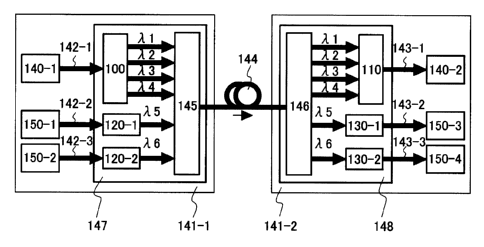
Fig. 1 is a schematic view of a first embodiment of a wavelength division
multiplexing
optical transmission system according to the present invention. A wavelength
division multiplexing optical transmission device (transmitting side) 147 and
a
CA 02319905 2000-09-19
11
wavelength division multiplexing optical transmission device (receiving side)
148 are
respectively disposed on two sites, (transmitting) 141-1 and (receiving) 141-
2.
An information communications device 140-1 sends out an information signal to
be
transmitted to a transponder device (referred to hereafter as transponder)
100. The
transponder 100 is disposed inside the wavelength division multiplexing
optical
transmission device 147, via an intra-site optical fiber circuit 142-1. In the
transponder 100, the information signal is demultiplexed and converted to four
optical signals of mutually different wavelengths J~1 - A4 at a lower speed
than the
transmission speed of the intra-site fiber circuit 142-1. The optical signals
are then
converted again to a signal format and wavelength suitable for inter-site
transmission. The optical signal output by the transponder 100 is wavelength
division multiplexed by an optical multiplexer 145, and transmitted to an
inter-site
optical fiber circuit 144. Information signals from information communications
devices 150-1, 150-2 are sent to the optical multiplexer 145 via transponders
120-1,
120-2, which are known in the art. The information signals from information
communications devices 150-1, 150-2 are then wavelength division multiplexed
and
transmitted to the receiving side site 141-2 by the inter-site optical fiber
circuit 144
together with the information signal from the information communications
device
140-1 of this invention.
On the receiving side site 141-2, the received wavelength division multiplexed
optical
signal is demultiplexed into each of the original optical wavelengths by an
optical
demultiplexer 146. A transponder 110 receives the four optical signals of
CA 02319905 2000-09-19
12
wavelengths ~1 - A4, multiplexes them again into an optical signal of one time
sequence, sends them to an intra-site optical fiber circuit 143-1, and
transmits them
to an information communications device 140-2 For the sake of simplicity, in
Fig. 1,
the sites are limited to being a transmitting site or a receiving site,
although in
practice both sites may have transmitting and receiving functions.
Fig. 2 shows the construction of one embodiment of a transponder 116 according
to
the present invention. In this embodiment, the site comprises both the
transponder
100 and 110 of the transmitting part/receiving part In this figure, the thick
arrows
show optical fibers and the thin arrows show electrical paths. The same
numbers
are assigned to parts which are effectively identical to the construction of
the
diagram described earlier, and a detailed description of them is omitted.
In the transponder 100 of the transmitting part, the optical signal
(wavelength J~a)
input from the intra-site side input fiber 142 is received by an intra-site
transmission
optical receiver 103, converted to an information signal in an electrical
area, and
demultiplexed into multiple (four in the diagram) information signals via a
demultiplexing circuit 105. In the electrical circuit, these information
signals are
normally transmitted in parallel, but the number of signals is not necessarily
the
physical number of signal lines and may represent a theoretical number of
signal
circuits. The demultiplexed information signals are respectively sent to inter-
site
transmission optical transmitters 104-1 - 104-4. After converting the
demultiplexed
information signals to an optical signal format for inter-site transmission
where each
signal has mutually different optical signal wavelengths suitable for
wavelength
CA 02319905 2000-09-19
13
division multiplexing transmission, the signals are output to inter-site side
output
optical fibers 102-1 - 102-4.
In the transponder 110 of the receiving part, the optical signals input from
inter-site
side input optical fibers 111-1 - 111-4 are respectively received by inter-
site
transmission optical receivers 113-1 -113-4. After converting the optical
signals to
electrical signals, they are again time division multiplexed into one signal
by a
multiplexing circuit 115, converted to a high-speed signal of wavelength ha by
the
intra-site transmission optical receiver 114 and output from an intra-site
side output
fiber 143.
Any kind of optical device capable of separating light according to wavelength
may
be used for the optical demultiplexer 146. For example, an optical fiber
grating and
an optical circulator may be serially connected; an AWG (Arrayed Wave Guide);
a
combination of an optical coupler and an optical band pass filter; a Mach-
Zehnder
type interferometer; or any cascaded combination of these devices may be used
as
the optical demultiplexer 14fi. An identical optical device may be used as the
optical
multiplexer 145, without necessarily having wavelength selectivity and may,
for
example, be an optical coupler or the like.
In Fig. 2, the wavelengths of the input and output optical signals of the
intra-site
circuits are ha and hb, but identical wavelengths may also be used. Further,
the
optical signal wavelengths transmitted between the inter-site circuits 102,
111 are
the four wavelengths h1 - )~4, as wavelength control is easiest for this case.
CA 02319905 2000-09-19
14
However, the operation is unaffected even if the input/output wavelengths are
different. Further, the number of signals, number of optical transceivers or
bit rate
may be different on the uplink and downlink according to the transmission
capacities
of the uplink circuit and downlink circuit.
The invention is not limited by this embodiment, and if there are multiple
intra-site
circuits, these may perform wavelength division multiplexing transmission on
one
optical fiber circuit. The uplink/downlink circuits may also be multiplexed
using an
optical circulator or optical coupler, and one optical fiber circuit may be
used for two-
way transmission. Further, wavelength division multiplexing and two-way
transmission can be applied simultaneously.
Fig. 3 shows the construction of an embodiment of the transponder 100
according to
the present invention. This embodiment comprises a transmitting optical source
which uses wavelength variable lasers 262-1 - 262-4.
The high-speed information signal from the intra-site optical fiber 142 is
demultiplexed into four signals by the demultiplexing circuit 105 via the
optical
receiver 103. These four signals are respectively applied to external optical
modulators 263-1 - 263-4 which modulate the output light of the wavelength
variable
lasers 262-1 - 262-4, and the result is output as an inter-site optical
signal. The
output wavelengths A1 - A4 are preset to wavelengths required for inter-site
transmission, or are set to desired wavelengths by an internal wavelength
reference
circuit or external control signal.
CA 02319905 2000-09-19
1$
By using this wavelength variable laser, one transponder can be used for a
wavelength division multiplexing optical transmission device requiring any
wavelength, so the invention has wider utility.
The variable wavelength laser 262 may be any of a number of different types of
lasers, such as, for example, an external cavity type which uses a
semiconductor
laser, or a fiber ring laser. The output light of a laser which outputs
optical signals of
plural wavelengths may also be multiplexed according to each wavelength.
Further,
the wavelength variable function can be implemented even if only the laser
part can
be individually replaced.
The external optical modulator 263 may be, for example, an electro-absorption
type
semiconductor optical modulator, or a semiconductor or lithium niobate type
Mach-
Zehnder type optical modulator. A modulation scheme such as phase modulation
or
duo-binary modulation can also be used.
Fig. 4 shows the construction of one form of the multiplexing circuit 115 used
for the
aforesaid transponder of the receiving part. This form shows an example of the
construction when SONET multiplexing is performed using SONET signals for
input/
output. This is input from four input circuits 211-1 - 211-4.
For example, 2.5Gbit/s OC-48 are respectively input to low speed circuit
terminal
circuits 220-1 -220-4, header information 224 is extracted such as the section
CA 02319905 2000-09-19
16
overhead in the SONET frame, encoding errors are detected and upstream
equipment fault information is extracted, and terminal processing such as
frame sync
is performed. The information signals contained in the payload are sent to a
SONET
multiplexing circuit 221 and are multiplexed into a high-speed signal. At the
same
time, the low speed circuit header information that was extracted is input to
a header
information processing circuit 223 together with a device internal state
signal 225
pertaining to the device, edited as high-speed circuit header information, and
sent to
a high-speed circuit terminal circuit 222. The header information 226 is again
added
to the multiplexed information signal by the high-speed circuit terminating
circuit 222,
and pointer processing or the like is performed. The signal is then converted
to a
10Gbit/s OC-192 signal, and is output from an output circuit 212. The
demultiplexing
circuit has effectively the reverse construction.
This embodiment was described in the case where the input/output signal
formats
were both SONET signals. At least one of the input or output may be another
signal
format such as ATM, Gigabit Ethernet or wavelength wrapping, each resulting in
slightly different signal terminal configuration and format conversion
construction.
The transmission speed after multiplexing also depends on the input/output
signal
format and it is not necessarily equal to the sum of the input circuits. For
example, in
the aforesaid wavelength wrapping, it may occur that an error correction
information
signal is added and the transmission bit rate increases by about 10 to 20
percent.
Further, it may also occur in the case of IP packet transmission that the bit
rate after
multiplexing by statistical multiplexing falls. The above is identical in the
case of
demultiplexing.
CA 02319905 2000-09-19
17
Hence, according to the present embodiment, by converting high-speed intra-
site
optical circuit signals to low speed wavelength division multiplexed signals
and
performing long-distance (inter-site) transmission, in the inter-site part,
the bit rate
can be decreased to a value at which long-distance transmission is possible,
sufficient transmission distance can be obtained and there is no longer any
need to
shorten the inter-site repeater interval even if the intra-site circuits are
high speed
circuits. Conversely, by applying the present invention to existing wavelength
division multiplexing optical transmission devices, the intra-site circuit
speed can be
increased without having an adverse effect on the transmission distance or
wavelength arrangement.
For example, if the transmission speed is 2.5Gbit/s per wavelength in the
inter-site
wavelength multiplexing circuit of the wavelength division multiplexing
optical
transmission devices 152, 153 in Fig. 5, an attempted to increase the intra
and inter-
site circuit speed by, for example, four times to 10Gbit/s, in the prior art
was difficult.
This difficulty was due to the fact that the wavelength division multiplexing
transmission device is normally designed assuming a speed of 2.5Gbit/s. For
example, if the transmission bit rate is increased to high speed, the
wavelength
spectrum of the wavelength division multiplexed signals largely widens or the
receiving sensitivity of the optical receiver deteriorates, so transmission
characteristics deteriorate. If the transmission devices 152, 153 were
replaced by
10Gbit/s devices, for example, the maximum transmission distance or maximum
span interval would decrease for an optical transmission device of 10Gbit/s as
CA 02319905 2000-09-19
Ig
compared to 2.5Gbit/s, so there would be a need to place more optical
wavelength
division multiplexing repeaters in the inter-site circuit and the system would
become
more costly.
S On the other hand, in the wavelength division multiplexing transmission
system of
the present invention, even if the speed of the inter-site interface is
increased to, for
example, 10Gbit/s, wavelength division multiplexing transmission can still be
performed in the inter-site part at 2.5Gbit/s, which is the prior art bit
rate, so the
above problem is avoided. Due to the increase of transmission speed, the
transmission distance in the intra-site interface part becomes shorter, but as
the ,
transmission distance in the intra-site transmission part is only several to
several
tens of kilometers at most, this is not a problem in practice. As a result,
the number
of intra-site circuits and intra-site interfaces can be reduced to 1/4 as
compared to
the prior art method, which offers a great advantage in terms of circuit
management
and cost. Also, if high speed intra-site interfaces such as 40Gbit/s or
160Gbit/s are
used, the number of intra-site circuits can be further reduced.
In the wavelength division multiplexing transmission system of this invention,
the
transmission speed of the intra-site/inter-site circuits is not limited to the
above
values, and can be set freely provided that the intra-site circuit speed is
greater than
the inter-site circuit speed at which wavelength division multiplexing
transmission
takes place. For example, the intra-site circuit speed may be set to 40Gbit/s
and the
inter-site transmission speed to 10Gbit/s, or the inter-site transmission
speed may be
set to 5Gbit/s and the intra-site circuit speed to 10Gbit/s, 20Gbit/s or
40Gbit/s.
CA 02319905 2000-09-19
19
Further, if one intra-site circuit is split between multiple inter-site
circuits, there is no
need to divide it into signals of equal transmission speed. There is also no
problem
if an intra-site circuit signal of, for example, 10Gbit/s is split into two
signals for
transmission, i.e., SGbit/s and 2.5Gbit/s, according to the characteristics of
the
equipment on the transmitting and receiving sides. If the distance between the
information communications devices and transponders is short, the intra-site
optical
fiber circuits 142-1, 143-1 do not necessarily have to be optical circuits
which use
optical fibers, and transmission is possible also using coaxial cables or
parallel
electrical signals. In the embodiment of Fig. 1, the case was shown where this
invention was applied to both the transmitting and receiving sites, but this
is not
absolutely necessary. It is possible to have a construction where the
transponder of
the present invention is applied to only one of either of the transmission
side or
receiving side sites.
The wavelength division multiplexing transmission system of the present
invention
resolves the problem of transmission distance, that occurs in optical signal
transmission at speeds of several Gbit/s and above by using the wavelength
division
multiplexing technique that is unique to optical transmission. The present
invention
reduces costs, cuts down the number of circuits and extends the transmission
distance of the inter-site optical interface part by converting the intra-site
optical
interface part to high-speed, and is different from the prior art inverse MUX
method.
Therefore, the application range of the present invention covers wavelength
division
multiplexing transmission devices, transponders and information communication
devices connected to them and their interfaces, and wavelength division
multiplexing
CA 02319905 2000-09-19
transmission systems using these devices, so the embodiments are also unique
to
these devices and systems.
In addition to the IM/DD (direct modulation/direct reception) method for
5 semiconductor lasers in wavelength bands such as the 1.3 Nm band often used
for
intra-site transmission signals, the 1.5 Nm band or external optical
modulation
method can also be used. According to this embodiment, particularly because of
the
high intra-site circuit transmission speed, the external modulation method may
prove
to be more suitable than the prior art direct modulation method. Further, the
signal
10 may be wavelength division multiplexed and transmitted together with
signals from
other intra-site circuits, and if necessary, dispersion compensated or
optically
amplified. It should be noted that the term "intra-site" may in practice be
used also
for connections between plural sites or information communications devices
where
intra-site circuits are disposed at close distances (several tens of km).
As the wavelength of the inter-site transmission optical signal, a wavelength
suited to
wavelength division multiplexing transmission is used. In addition to signals
in the
1.5 Nm band suitable for amplification by optical fibers and in compliance
with the
wavelength grid specified as the wavelength for WDM by ITU-T, the 1.3 Nm band
can also be used. In particular, as the inter-site transmission bit rate can
be reduced
in this wavelength division multiplexing transmission system, in some cases,
not only
a modulation scheme such as external optical modulation but also a low chirp
LD or
the like can be used.
CA 02319905 2000-09-19
21
As the intra-site/inter-site optical signal format, the signal format of the
intra-site
optical fiber circuit 142-1 may use, for example, SONET/SDH. For example, in
the
case of the OC-192 signal (10Gbit/s), the output signal of the transponder 100
may
be separated into four OC-48 signals (2.5Gbit/s), but any other desired format
can
be used.
Embodiment 2
Fig. 8 is a schematic view of a second embodiment of the wavelength division
multiplexing optical transmission device (transmitting side) according to the
present
invention.
In a wavelength division multiplexing optical transmission device
(transmitting side)
160, optical signals input from the intra-site side input fibers 142-1, 142-2
are
respectively received by transponders (transmitting side) 100-1, 100-2,
demultiplexed and converted into multiple (four in Fig. 8) optical signals
suitable for
wavelength division multiplexing for low speed inter-site transmission, and
output
from the inter-site side output optical fiber 102. These signals are
wavelength
division multiplexed by the optical multiplexer 145, amplified by an optical
amplifier
161, and output to an inter-site optical fiber circuit 162. Optical amplifiers
or means
to perform dispersion compensation and prevent signal quality and waveform
deterioration can further be added to the inter-site/intra-site circuit part
as desired. In
this embodiment, an example is shown where signals from the prior art
transponders
120-1, 120-2 are also input to the optical multiplexer 145, wavelength
division
multiplexed, and transmitted.
CA 02319905 2000-09-19
22
In the diagram, the output wavelengths of the inter-site side output fiber 102
of the
transponder 100-1 are I~1,1~2, ~9 and ~3. There is no particular limitation on
the
order or interval of these wavelengths provided that the signal wavelengths
output to
the same inter-site fiber are mutually different.
For example, if the inter-site optical fiber circuit is a dispersion shift
fiber, to suppress
the optical four-wave mixing effect, a wavelength arrangement with unequal
intervals
can be adopted.
Embodiment 3
Fig. 9 shows a schematic view of a third embodiment of a wavelength division
multiplexing optical transmission device (receiving side) according to this
invention.
This embodiment is a device which receives the optical multiplexed signals
from the
wavelength division multiplexing transmission device (transmitting side) of
Fig. 8.
In a wavelength division multiplexing optical transmission device (receiving
side)
164, the wavelength division multiplexed optical signal input from an inter-
site side
input fiber 163 is amplified if necessary by the optical amplifier 161, and
demultiplexed into separate wavelengths by the optical demultiplexer 146. Also
according to this embodiment, if necessary, optical amplifiers or optical
dispersion
compensating means may be added as required to the inter-site/intra-site
circuit
parts. The optical signals demultiplexed into each wavelength are respectively
received by transponders (receiving side) 110-1, 110-2 according to the
present
CA 02319905 2000-09-19
23
invention and the prior art transponders 130-1, 130-2.
In each of the transponders 110-1, 110-2, the four signals received from the
inter-site
circuit are respectively multiplexed into one high-speed intra-site signal,
and output
to the intra-site circuits 143-1, 143-2. In the case of the prior art
transponders 130-1,
130-2, the received inter-site optical signals are converted to intra-site
optical signals
and output at the same transmission speed.
The four wavelengths 7~1, ~2, h9, A3 are received from the inter-site side
input fiber
111 of the transponder 110-1, but there is no particular limitation on the
order or
interval of these wavelengths. In principle, a 1:1 correspondence between the
intra-
site circuits in the transponders on the transmitting/receiving sides is
achieved by
maintaining correspondence with the transponders on the transmitting side. In
an
embodiment described hereafter, an example is shown wherein the wavelength
arrangements on the transmitting and receiving sides are purposely arranged to
be
different.
Embodiment 4
Fig. 10 is a schematic view of a fourth embodiment of the wavelength division
multiplexing optical transmission device according to the present invention. A
wavelength division multiplexing optical transmission device 165 of this
embodiment
basically comprises the wavelength division multiplexing optical transmission
devices
on the transmitting side and receiving side of Fig. 8 and Fig. 9 in a one-
piece
construction. Although prior art transponders are not used, they can be added.
CA 02319905 2000-09-19
24
An optical signal input from the inter-site side input optical fiber 163 is
demultiplexed
into eight wavelengths h1 - I~8 by the optical demultiplexer 146. These 8
wavelengths are input to the transponders 110-1, 110-2 (receiving side) four
wavelengths at a time, and multiplexed into high-speed intra-site circuit
signals that
are respectively output from the intra-site optical fiber circuits 143-1, 143-
2. The
intra-site circuit signals input from the intra-site optical fiber circuits
142-1, 142-2 are
also respectively demultiplexed to inter-site transmission optical signals of
wavelengths 7~1 - h4 and A5 - 7~8 by the transponders 100-1, 100-2, wavelength
division multiplexed by the optical multiplexer 145, and output from the inter-
site side
output optical fiber 162.
In the embodiment shown, an information communications device 166 is built
into
the wavelength division multiplexing optical transmission device 165. In this
embodiment, the intra-site optical circuits 143-2, 142-2 interconnect the
transponders
110-2, 100-2 and the information communications device 166 inside the
wavelength
division multiplexing optical transmission device 165.
The information communications device 166 may comprise various devices such as
a SONET/SDH terminal device, IP router, ATM terminal or ATM switch. As
input/output circuits 167 connecting with the outside, various circuits may be
used
such as SONET/SDH circuits, ATM circuits, Ethernet circuits such as Gigabit
Ethernet, or FDDI circuits. If the distance between the information
communications
device 166 and the transponders 100-2, 110-2 is short, the intra-site optical
fiber
CA 02319905 2000-09-19
circuits 143-2, 142-2 are not necessarily optical circuits using optical
fibers, and
transmission may be effected by coaxial cables or parallel electrical signals.
Also,
conversely to the embodiment of Fig. 10, the construction may comprise the
transponder or wavelength division multiplexing optical transmission device of
this
5 invention as part of the information communications device 166.
Embodiment 5
Fig. 11 is a schematic view of a second embodiment of the wavelength division
multiplexing optical transmission system according to this invention. This
10 embodiment is an example wherein the sites 141-1, 141-2 are connected by
the two
uplink/downlink inter-site optical fiber circuits 144 using wavelength
division
multiplexing optical transmission devices 165-1, 165-2 having an integral
transmitting/receiving construction identical to that of Fig. 10.
15 A linear optical repeater 151-1 using an optical amplifier is disposed
midway in the
inter-site optical fiber circuits 144-1, 144-2, and amplifies a wavelength
division
multiplexed optical signal which has been attenuated by optical fiber losses.
The
wavelength division multiplexing number of this type of wavelength division
multiplexing optical transmission system may exceed a maximum of 100
20 wavelengths. In the prior art the same number of intra-site circuits was
required,
whereas according to this embodiment, multiple inter-site circuits can be
multiplexed
and connected to an information communications device 140. This reduces the
number of intra-site optical fiber cables or circuits thus increasing
manageability.
Further, according to this embodiment, the information communications device
140
CA 02319905 2000-09-19
26
and wavelength division multiplexing optical transmission device 165 are
connected
by one of the intra-site optical fiber circuits 142, 143 each for the
uplink/downlink, but
they may be connected by multiple circuits.
Embodiment 6
Fig. 12 is a schematic view of a fifth embodiment of the wavelength division
multiplexing optical transmission device according to the present invention.
This
embodiment shows a construction wherein a wavelength division multiplexing
optical
transmission device 170 uses an optical repeater. This repeater first converts
the
optical signal to an electrical signal, and then performs waveform
regeneration, re-
timing and amplification.
The wavelength division multiplexed optical signal input from the inter-site
side input
optical fiber 163 is amplified by an optical amplifier 161-1, and
demultiplexed to
individual wavelength components by the optical demultiplexer 146. Of these,
the
optical signals of wavelengths l~1 - l~4 are multiplexed into one intra-site
optical
signal by the transponder (receiving side) 110-1, and transmitted to the
transponder
(transmitting side) 100-1. These signals are again demultiplexed according to
the
wavelength division multiplexed signals l~1 - J~4 for inter-site transmission,
wavelength division multiplexed by the optical multiplexer 145, and output to
the
inter-site side output optical fiber 162.
In the repeater 170 according to this embodiment, signals are first relayed
via the
high-speed intra-site optical fiber circuit 142-1. This has the advantages
that the
CA 02319905 2000-09-19
27
signals in this circuit can be add-dropped, an information communications
device is
easily connected, and mutual interconnections using transponders from
different
manufacturers on the transmitting side and receiving side are easily made.
When
the distance between the transponders 110-1, 100-1 is short, the optical fiber
circuit
142-1 may be replaced by an electrical signal circuit. There is a further
advantage in
that this optical repeater device comprises multiple wavelength division
multiplexing
devices, so even if the optical demultiplexer 146 and optical multiplexer 145
are
separated far from each other, the number of intra-site circuits can be
decreased and
control is easy.
Although add-drop of a prior art inter-site transmission signal is possible
even with a
combination of the prior art transponders (transmitting side) 130, (receiving
side)
120, and 171 (for regenerating) , it is difficult to demultiplex multiple
wavelengths and
access transmitted information signals. For example, in this embodiment, an
example of an add-drop construction is shown where the intra-site side output
fiber
142-3 of the transponder (receiving side) 110-2 and intra-site side input
fiber 142-4
of the transponder (transmitting side) 100-2 are connected to an intra-site
circuit
interface of the information communications device 140. Specifically, the
optical
signals transmitted with wavelengths 7~1 - J~4 are dropped in this repeater
and passed
to the information communications device 140, and the output signal of the
information communications device 140 is added to the same wavelengths and
then
transmitted over the inter-site circuit. Thus, when signals are relayed using
the
transponder of this invention, an information communications device using this
invention can easily be connected to effect an upgrade by an add-drop
construction.
CA 02319905 2000-09-19
28
Also in this embodiment, dispersion compensation may be performed to
compensate
for waveform deterioration or signal strength of the optical signal, and
optical
amplifiers may be inserted in the signal circuit as may be appropriate. SONET
signal
or other signal terminal circuits may also be disposed in the transponders
110, 100
as necessary. Further, plural inter-site circuit parts such as uplink/downlink
circuits
may be combined to form one wavelength division multiplexing optical repeater.
Embodiment 7
Fig. 13 is a schematic view of a sixth embodiment of the wavelength division
multiplexing optical transmission device according to the present invention.
This
embodiment is an example wherein variable add-drop and cross-connect functions
are added to the optical repeater
In this embodiment, information signals obtained by demultiplexing inter-site
side
input optical fibers 163-1, 163-2 into low speed inter-site wavelength
division
multiplexed signals are multiplexed into high speed intra-site signals by the
transponders (receiving side) 110-1, 110-2, and output to the intra-site
optical fiber
circuits 142-1, 142-2. Also, an information signal from the information
communications device 140 is output to the intra-site optical fiber circuit
142-3.
These signals are connected to a three-input/three output optical switch
matrix 172,
and connected to the intra-site optical fiber circuits 143-1, 143-2, 143-3 by
an
external control signal as desired. The intra-site optical fiber circuits 143-
1, 143-2
are respectively connected to the transponders 100-1, 100-2 and to the inter-
site
CA 02319905 2000-09-19
29
optical fiber circuits 162-1, 162-2 via the multiplexers 145-1, 145-2, and the
remaining intra-site optical fiber circuit 143-3 is connected to the
information
communications device 140 of this invention. In other words, the connection
state
between the inter-site circuits and information devices can be varied as
desired by
changing over the optical switch 172 depending on changes in the traffic
pattern or
accidents such as fiber breaks.
In the case of this variable add-drop/cross-connect device, according to this
embodiment, as plural inter-site circuits are converted into one of the high-
speed
intra-site circuits 142, there is an advantage in that the scale of the
optical switch
required need only be 1/N compared to the prior art technique. In the example
of
four wavelength multiplexing of this embodiment, whereas four sets of the
optical
switches 172 would be required in the prior art, only one set is needed in
this
example which is advantageous from the viewpoints of low-cost, high
reliability and
device scale. In this embodiment also, only one-directional transmission is
shown,
but the uplink/downlink circuit parts may be combined. Further, the add-
drop/cross-
connect scheme between wavelength division multiplexed signals and plural
optical
fiber circuits is not limited to that shown here, any combination being
possible. For
example, N sets of wavelength division multiplexed signals in one inter-site
circuit
can be mutually interchanged, or the uplink circuit can be returned to the
downlink
circuit.
Embodiment 8
Fig 14 shows the construction of an embodiment of an intra-site interface for
an
CA 02319905 2000-09-19
information communications device according to the present invention. The
information communications device 140 comprises an information communications
device intra-site optical interface 195. The optical interface 195 comprises a
transmitting optical interface 180 and receiving optical interface 190. In
this
5 embodiment, the aforesaid transponders are connected with the optical
interfaces
180, 190 via intra-site side optical fibers 184 and 194.
In the transmitting optical interface 180, plural information signals input
via intra-
device circuits 183-1 - 183-4 are terminated/time division multiplexed by a
10 multiplexing circuit 182, converted to a high speed optical signal by an
intra-site
optical transmitter 181, and output to an intra-site side output light fiber
184. The
signal output by the optical fiber 184 must be a signal capable of being
received by
the aforesaid wavelength division multiplexing optical transmission device
connected
via intra-site optical fiber circuits, or by the intra-site transmission
optical receiver of
15 the transponder. Therefore, the multiplexing number and the signal format
before
and after multiplexing in the multiplexing circuit 182 is identical to that of
the
aforesaid wavelength division multiplexing optical transmission device or
transponder device according to this invention. The intra-device information
circuits
183-1 - 183-4 do not necessarily have to be one signal line, and may be
transmitted
20 in parallel using plural signal lines.
In the receiving side optical interface 190, an optical signal of wavelength
Jib sent
from the aforesaid wavelength division multiplexing optical transmission
device or
intra-site transmission optical transmitter of the transponder, is received by
an inter-
CA 02319905 2000-09-19
31
site transmission optical receiver 191 via an intra-site side optical fiber
194,
terminated if necessary, demultiplexed into the original low speed information
signals
by a demultiplexing circuit 192, and output from intra-device circuits 193-1 -
193-4.
This embodiment shows an example of an information communications device
provided with both a receiving side and a transmitting side optical interface,
but only
one of these optical interfaces may be provided.
Embodiment 9
Fig. 15 shows the construction of another embodiment of the information
communications device according to this invention. This embodiment also uses
the
intra-site optical interface (receiving side and transmitting side) of the
information
communications device.
This embodiment shows the construction of an IP router switch 200 as the
information communications device. Intra-site optical interfaces 195-1, 195-2
for the
information communications device 200 are connected to a switch matrix 202 via
a
routing module 201-1, and thereby form an IP router. The switch matrix 202 is
controlled by a routing control circuit 203, and IP packets input from the
interfaces
are transferred to a destination interface.
According to this embodiment, the intra-site interfaces 195 each
multiplex/demultiplex two of the low speed intra-device circuits 183. The two
intra-
device circuits 183-1, 183-2 are multiplexed by the intra-site interface 195-
1, and
output from the intra-site side output optical fiber 184-1 as a high speed
signal. After
CA 02319905 2000-09-19
32
these multiplexed signals have been transmitted through intra-site circuits,
they are
demultiplexed into each wavelength by the aforesaid wavelength division
multiplexing optical transmission device and transmitted. Therefore, if the
intra-
device circuits 183-1, 183-2 are treated as independent signal interfaces or
input/output ports, robustness to device faults can be improved, and as there
is no
need to consider the differential group delay of the two ports, the device
construction
can be simplified. Further, as independent routing is performed for each port,
a
configuration described hereafter is possible wherein a wavelength division
multiplexed signal is add-dropped or routed for each wavelength.
The information communications device according to this invention is not
limited to
this embodiment. Various constructions are possible, such as, SONET/SDH/ATM
multiplexing terminal devices comprising an intra-site interface or
transceiver
according to this invention, or demultiplexing/exchange/switching/fault
recovery/bit
rate conversion or add-drop devices.
Embodiment 10
Fig. 16 shows the construction of a third embodiment of the wavelength
multiplexing
optical transmission system according to the present invention.
In this embodiment, an example is shown wherein the three sites 141-1, 141-2
and
141-3 are connected by the inter-site optical fiber circuits 144-1, 144-2, but
only the
uplink circuit is shown for the sake of simplicity. In particular, a
wavelength add-drop
example is shown wherein, of those wavelength-routed and wavelength division
CA 02319905 2000-09-19
33
multiplexed optical signals obtained by assigning information signals divided
into
multiple wavelengths to different destinations for each wavelength, only
required
wavelengths are accessed.
A high-speed information signal sent by the intra-site circuit 142-1 from the
information communications device 140-1, is converted into wavelength division
multiplexed optical signals of wavelengths h1 - ~4 by the wavelength division
multiplexing optical transmission device 160, multiplexed by an optical
multiplexer
145-1, and transmitted to the inter-site optical fiber circuit 144-1.
In the wavelength division multiplexing optical transmission device 170, the
signals
of wavelengths h1 and J~2 of the received wavelength division multiplexed
optical
signals are dropped, and sent to the information communications device 140-2
via
the transponder 110-1. The information signal from the information
communications
device 140-2 is divided into the two wavelengths, h1 and )~5, by the
transponder 100-
2, multiplexed with the optical signals of wavelengths h3, J~4 that are
through signals.
The signals are transmitted to the wavelength division multiplexing optical
transmission device 164 via the inter-site optical fiber circuit 144-2. The
signals of
wavelengths h3, h4, ~5 are multiplexed by the transponder 110-2, and sent to
the
information communications device 140-3. The signal of wavelength h1 is
received
by the prior art transponder 130, and sent to the prior art information
communications device 150.
According to this embodiment, one intra-site circuit signal is demultiplexed
into plural
CA 02319905 2000-09-19
34
wavelengths for transmission. To achieve wavelength routing or wavelength add-
drop, the information signals must have separate contents and destinations for
each
wavelength. Specifically, in the information transmission device of this
invention,
multiple independent intra-device signal circuits/interfaces/input-output port
signals
corresponding to the number of wavelengths in the inter-site part should be
multiplexed in advance as one intra-site circuit. If this is done, the optical
signals
after wavelength demultiplexing can be given full compatibility with prior art
wavelength division multiplexed optical signals, so prior art transponders or
optical
wavelength division multiplexing transmission devices may be freely mixed with
the
other devices to construct the optical transmission system.
Embodiment 11
Fig. 17 shows the construction of a second embodiment of an intra-site
interface for
the information communications device according to the present invention. In
this
embodiment, some of the plural wavelengths used for information transmission
in the
inter-site part are used, so it is used for fault recovery with redundancy.
The
information communications device in the other site connected by the inter-
site
optical fiber circuits also comprises an intra-site interface identical to
that of this
embodiment.
In the transmitting part of an intra-site interface 230, header information
such as
circuit status or priority is added by header adding circuits 235-1 - 2 to the
three
intra-device circuits 183-1 - 183-3 and the information signal of an intra-
device circuit
231 of low priority, multiplexed by the multiplexing circuit 182, and output
to the high-
CA 02319905 2000-09-19
speed intra-site circuit 184.
In the receiving part, a signal of the intra-site circuit 194 is demultiplexed
by the
demultiplexing circuit 192, the header information of each signal is extracted
by
5 header extracting circuits 236-1 - 236-4, a switching circuit 234 is
controlled by a
switch control circuit 237 using this header information, and information
signals are
output as the intra-site circuits 193-1 - 193-3 and a low priority intra-
device circuit
232. When there is a fault of the wavelength division multiplexing transmitter
in the
inter-site circuit part, this situation is detected from header information
238, and the
10 switch control circuit 237 performs a recovery operation by changing over
switching
circuits 233, 234 according to the status.
For example, if one of the inter-site circuits corresponding to the received
intra-
device circuits 193-1 - 193-3 has a malfunction, a 3:1 fault recovery
mechanism can
15 be implemented wherein this situation is notified to the transmitting side
using the
header information, the switching circuit 233 is changed over on the
transmitting/receiving sides, and the information is transmitted instead to
the low
priority circuit 231, which is a standby circuit. The capacity allocation of
the standby
circuit and the switching algorithm are not limited to the above, and a
recovery
20 mechanism such as for example 1+ 1 can also be employed. In particular,
when an
IP router or the like is used as the intra-site device and the multiple intra-
device
circuits of this invention are considered as independent interfaces, they may
be
treated as multiple delivery routes so a fault recovery function can be
implemented
without providing a special standby circuit
CA 02319905 2000-09-19
36
Further, in this embodiment, an example is shown where a fault
monitoring/notification/error rate correction function of the intra-site
circuit is added to
the high-speed intra-site circuit part. This function can be used completely
independently regardless of whether or not the aforesaid fault recovery
mechanism
is provided. A header information extracting/error correcting circuit 241
extracts the
header information 244 or error correction signal from the high-speed signal
received
by the intra-site transmission optical transmitter 191, and performs error
correction if
necessary. Part of this header information is input to an intra-site circuit
header
information processing circuit 243. In a header addition/error correction
information
adding circuit 242, the fault and alarm status of the devices, the status of
the
received intra-site circuit, a CRC (Cyclic Redundancy Check) or FEC (Forward
Error
Correction) signal which performs error detection or error correction on the
transmitted information signal, and a parity bit, are added to the information
signal,
and output from the intra-site transmission optical transmitter 181.
Addition/extraction of the header information does not necessarily have to be
performed after multiplexing, and may be performed simultaneously with
multiplexing/demultiplexing by the multiplexing/demultiplexing circuit 234, or
may be
performed on the low speed signal before multiplexing/demultiplexing. Further,
this
added information is not necessarily in the form of headers, but may for
example be
time division multiplexed and transmitted together with the information signal
as
another circuit.
Embodiment 12
CA 02319905 2000-09-19
37
Fig. 18 shows a third embodiment transponder according to the present
invention.
This embodiment is an example wherein a fault recovery mechanism and intra-
site
circuit error correction/monitoring mechanism is incorporated in the
transponder part.
The fault recovery mechanism, which is identical to the mechanism shown in
Fig. 17,
determines the fault status of inter-site circuits from header information
extracted
from the inter-site transmission optical receivers 113-1 - 113-4. The
switching
control circuit 237 performs fault recovery by switching over important
signals to
standby circuits by the transmitting side and receiving side switching
circuits 233,
234. In Fig. 18, one of the inter-site optical fiber circuits 102-1 - 102-4
and one of
111-1 - 111-3 is assigned to a standby circuit. Identical functions and
component
parts to the construction of Fig. 17 are given the same symbols, and their
description
is omitted.
This embodiment also shows an example where circuit fault
control/notification/error
rate correction functions are added to the high-speed intra-site circuit part.
This
transponder must be connected opposite to intra-site interface devices and
transponders having identical functions. The header information
extraction/error
correction circuit 241 extracts header information or an error correction
signal from
the high-speed signal received by the intra-site transmission optical receiver
103,
and performs error rate correction if necessary. Part of the header
information is
input to the intra-site circuit header information processing circuit 243. In
the header
addition/error correction information adding circuit 242, header information
is again
added to the information signal, and output from an intra-site transmission
optical
transmitter 114. This embodiment shows only a construction where transmitting
and
CA 02319905 2000-09-19
- 38
receiving functions are integrated, but the transmitting side and receiving
side may
be provided separately.
Embodiment 13
Fig. 19 shows the construction of a third embodiment of the intra-site
interface of
information communications device according to the present invention. This
embodiment is an example wherein the intra-site optical fiber circuit part is
duplexed,
and a fault recovery mechanism is added.
The signal from the intra-device circuits 183-1 - 183-4 is multiplexed by the
multiplexing circuit 182, the multiplexed intra- device signal is split into
two by a
splitting circuit 245, and the two intra-site circuit optical transmitters 181-
1, 181-2
always transmit an identical signal to two intra-site optical fiber circuits
184-1, 184-2.
In the receiving part, two circuits of optical signals are always received by
two intra-
site circuit optical receivers 191-1, 191-2. The intra-site circuit header
information
processing circuit 243, which receives header information 244 extracted from
the
received signals, always selects and outputs the higher quality circuit by
changing
over a switching circuit 246, and sends it to the demultiplexing circuit 192.
According
to this embodiment, the intra-site circuit part is a high-capacity circuit,
and as there
are not many circuits, the improvement of reliability due to this fault
recovery
mechanism based on duplication is effective.
Fig. 20 is a transponder having an intra-site circuit duplex function
connected
opposite the device of Fig. 19. In this embodiment also, the intra-site
circuit optical
CA 02319905 2000-09-19
39
transmitters 114-1, 114-2 always transmit identical information, always select
the
higher quality or correct signal from the intra-site circuit optical receivers
103-1, 103-
2, and send it to the intra-device circuit.
The two duplexed intra-site circuits may respectively use independent optical
fiber
circuits, or may perform wavelength division multiplexing transmission by one
optical
fiber circuit using different wavelengths. Moreover, the aforesaid recovery
mechanism can be applied without any problem even if intra-site interfaces or
transponders are connected together The mechanism is not limited to a 1:1
fault
recovery mechanism as in this example, and can be applied without problem to
constructions such as 1+1 or N:1. It may also be applied to a scheme where,
for
example, one of plural intra-site circuits always transmits signals of low
priority as a
standby circuit. The above two embodiments show only a construction where
transmitting and receiving functions are integrated, but the transmitting side
and
receiving side may be provided separately.
Embodiment 14
Fig. 21 shows yet another embodiment of the transponder according to this
invention. In this embodiment, an information signal routing mechanism is
built in to
the transponders in both the transmitting part and receiving part. There is no
particular limitation if it is built into one of the transmitting part and
receiving part or
on the intra-site interface device side, and routing may be performed in
plural
devices. According to this embodiment, the speed of the intra-site circuit is
approximately twice the speed of the inter-site circuit.
CA 02319905 2000-09-19
In the transmitting part, signals input from two intra-site side input fibers
142-1, 142-2
are respectively demultiplexed into low speed signals in demultiplexing
circuits 105-
1, 105-2, and input to a routing module 251-1. The routing module 251-1 sends
5 signals to the inter-site optical transmitters 104-1 -104-4 corresponding to
destinations based on address information embedded in the packetized
information
signals and routing information supplied from a routing control circuit 250.
The routing control circuit 250 constantly updates a routing table based on
control
10 packet information and device status/fault status/circuit congestion, etc.
Likewise,
the receiving part routes information signals received from four inter-site
optical fiber
circuits 111-1 - 1'11-4 to desired circuits by a routing module 251-2,
multiplexes this
information, and outputs it from the intra-site side optical transmitters 114-
1, 114-2.
15 If a routing mechanism is built in, routing efficiency is improved, and the
device
construction can be made more flexible. Also, a detour route can be set in
case of
device failure on both the intra-site and inter-site sides, so reliability is
improved.
Embodiment 15
20 Fig. 22 is a diagram showing the construction of yet another embodiment of
the
transponder according to this invention.
In this embodiment, a propagation delay difference compensating circuit 252 in
the
inter-site circuit is built into the receiving side transponder. It is
possible that mutual
CA 02319905 2000-09-19
41
propagation delay differences may occur between the optical signals received
from
the inter-site side input optical fibers 111-1 - 111-4 due to the wavelength
dispersion
characteristics of the inter-site optical fiber circuit which transmits a
wavelength
division multiplexed signal, or due to differences in the optical fiber cable
length of
each circuit before wavelength division multiplexing and after wavelength
demultiplexing.
There is no problem in treating these as mutually independent circuits,
however, the
bandwidth of the high-speed intra-site circuit can be used more effectively if
mutual
propagation delay differences are eliminated by propagation delay difference
compensating circuits 252-1 - 252-4.
For example, in the case where the inter-site optical fiber circuit is OC-16
(600Mbit/s)
four wavelengths, a signal which uses the full bandwidth of 2.5Gbit/s such as
OC
48c can be transmitted through the intra-site circuit, and the range of
application of
this invention is thereby widened.
The propagation delay difference compensating circuit 252 may employ a
variable
wavelength delay line or a buffer memory circuit. The propagation delay
difference
compensating circuit 252 may be installed on the receiving side of the intra-
site
interface circuit. In this case, the intra-site circuit multiplexes the signal
with the
propagation delay difference still present. As the intra-site interface having
a
propagation delay difference compensating mechanism need only be provided in
the
information communications device requiring propagation delay difference
CA 02319905 2000-09-19
42
compensation, it is advantageous from the viewpoints of cost and circuit
scale. In
principle, this embodiment may be implemented also by installing the
propagation
delay difference compensating circuit on the transmitting side of the
transponder or
intra-site interface.
Embodiment 16
Fig. 23 is a schematic view of yet another embodiment of the transponder
according
to this invention. According to this embodiment, a wavelength multiplexer and
wavelength demultiplexer are built into the transponder.
The output light from the inter-site side optical transmitters 104-1 - 104-4
is
wavelength division multiplexed by an optical multiplexer 253, and output to
an inter-
site side output optical fiber 102-5. This output light is transmitted without
modification, or after wavelength division multiplexing with another optical
signal, to
another site. Also, a wavelength division multiplexed optical signal input
from an
inter-site side input light fiber 111-5 is demultiplexed into wavelengths A1 -
h4 by an
optical demultiplexer 254, which are respectively received by inter-site side
optical
receivers 113-1 - 113-4. The optical multiplexer/demultiplexer may also be
built in to
only one of the transmitting side and receiving side.
If the wavelength multiplexer/demultiplexer 253 and optical demultiplexer 254
are
built into the transponder in this way, the number of optical fibers used for
inter-
device connections is less and the board size can be reduced. Further, by
providing
a delay difference for each wavelength in the transponder, the aforesaid
propagation
CA 02319905 2000-09-19
43
delay time compensating circuit can be easily implemented.
Embodiment 17
Fig. 24 is a schematic view of yet another embodiment of the transponder
according
to this invention. In this embodiment, all the transmitter/receiver parts of a
transponder 260 have a modular construction, and can be individually replaced.
A main frame 261 comprises the multiplexing circuit 105, demultiplexing
circuit 115,
and other monitoring control circuits or power supply circuits, not shown, and
the
intra-site side and inter-site side optical transmitters/receivers 102, 113,
104, 114 are
all provided as sub-modules or sub-substrates attached to the main frame.
According to this construction, maintenance and supervision of
transmitting/receiving
parts which are particularly prone to faults are easily performed. In
particular, in the
transponder of this invention, the multiple inter-site transmission optical
transmitters
104 for wavelength division multiplexing transmission are installed which are
fixed at
specific wavelengths. By adopting this construction, the volume of replacement
parts required when a fault occurs can be reduced. The modular construction is
not
limited to the transponder, and can be applied also to the wavelength division
multiplexing transmission device, intra-site interface device or intra-site
information
communications device of this invention, or to the intra-site optical
transmitter part,
receiver part or multiplexing circuit part so that any desired part can be
replaced.
The technical features of the embodiments of the invention may be summarized
as
follows:
CA 02319905 2000-09-19
44
The first optical signal transmitted at a transmission speed Rb through the
aforesaid
intra-site circuit is received, demultiplexed into two or more electrical
signals by a
demultiplexing circuit, two of the signals are converted to the aforesaid
second and
third signals, and these are wavelength division multiplexed and transmitted
to the
aforesaid inter-site circuit.
An optical signal is received from an inter-site circuit in which second and
third
optical signals of mutually different wavelengths are wavelength division
multiplexed
and transmitted, the signal is demultiplexed into the original wavelengths,
and these
are converted a first time sequence optical signal and transmitted to a first
intra-site
circuit.
The optical signal from the aforesaid inter-site circuit, in which second and
third
optical signals of mutually different wavelengths are wavelength division
multiplexed
and transmitted, is demultiplexed into the original wavelengths which are
respectively received and converted to electrical signals, multiplexed by a
multiplexing circuit, converted to the first time sequence optical signal, and
transmitted to the aforesaid first intra-site circuit.
The optical signal from an inter-site circuit, in which second, third and
fourth optical
signals of mutually different wavelengths are wavelength division multiplexed
and
transmitted, is demultiplexed into the original wavelengths, and the aforesaid
second
and third optical signals are converted to a first time sequence optical
signal and
CA 02319905 2000-09-19
transmitted to the first intra-site circuit, whereas the aforesaid fourth
optical signal is
wavelength converted and transmitted to a second intra-site circuit.
The optical signal from the aforesaid inter-site circuit, in which second,
third and
5 fourth optical signals are wavelength division multiplexed and transmitted,
is
demultiplexed into the original wavelengths which are respectively received
and
converted to said second, third and fourth electrical signals, and the
aforesaid
second and third electrical signals are converted to the aforesaid first time
sequence
optical signal and transmitted to the first intra-site circuit, whereas the
fourth optical
10 signal is wavelength converted and transmitted to the aforesaid second
intra-site
circuit.
At least a first optical signal of optical signals transmitted from first and
second intra-
site circuits at a transmission speed Rb through a first intra-site circuit is
received,
15 converted to an electrical signal and demultiplexed by a demultiplexing
circuit into
two or more electrical signals which are respectively converted into second
and third
optical signals of mutually different wavelengths, an optical signal sent from
the
second intra-site circuit is received, converted into an electrical signal and
then
converted into a fourth optical signal of different wavelength to the second
and third
20 optical signals, and the aforesaid second, third and fourth optical signals
are
wavelength division multiplexed and transmitted to an inter-site circuit.
According to the embodiments of the invention, the transmission speed of intra-
site
transmission can be made much higher than that of the inter-site part, so the
number
CA 02319905 2000-09-19
46
of circuits in the intra-site transmission part can be reduced, costs can be
lowered,
and maintenance can be performed easily. Further, as the bit rate of the inter-
site
transmission part can be suppressed low, the transmission distance can be made
a
long distance.