Note: Descriptions are shown in the official language in which they were submitted.
CA 02319936 2000-09-20
1
CABLE CONTROL APPARATUS FOR LIMITING
THE MOVEMENT OF OPTICAL FIBERS
BACKGROUND OF THE INVENTION
1. FIELD OF THE INVENTION
The present invention relates to optical fiber communication apparatus
and more specifically, to apparatus for limiting the movement of optical
cables
so as to avoid damage during connecting and disconnecting the cables in
space-restricted areas.
The telecommunications industry is using more and more optical or light
fibers in lieu of copper wire. Optical fibers have an extremely high band
width, thereby allowing significantly more information than can be carried by
a copper wire. However, optical fibers also require more careful handling and
attention during use to avoid damage or unsatisfactory operation. For
example, even the most robust optical fibers must not be bent or coiled with
a too small radius to avoid degradation of the transmission qualities of the
optical fiber. Transmission degradation can occur if the optical fiber is
coiled
or bent in a tight loop even though there is no physical damage done to the
optical fiber or cable.
Therefore, it is important to control the bends and coils that a fiber-optic
is subjected to during installation and subsequent maintenance operations.
DL: 1055148v1
560043-610080
CA 02319936 2000-09-20
2
SUMMARY OF THE INVENTION
It is an object of this invention to provide simple and inexpensive
equipment to help control coil size and limit the bend radius experienced by
an optical fiber during installation and maintenance.
It is a further object of this invention to provide equipment which
operates in conjunction with existing equipment and which provides support
for optical fibers during connecting and disconnecting of the fibers.
The present invention accomplishes these and other objects by
providing apparatus for controlling the movement of the optical cables during
installation or maintenance operations. The apparatus comprises at least one
cable, such as an optical cable, and a support structure which is associated
with the cable. An attachment member is selectively supported by the
support structure at a first location, and the attachment member is movable
between the first location and a second location. The fiber-optic cable is
secured to the attachment member. A cam plate is also secured to the
attachment member and the cam plate defines a pair of cam tracks. A pair
of cam followers or pins are supported in a fixed position with respect to the
support structure and the cam followers are received in the cam tracks such
that the movement of the attached member and the attached cable is
controlled by movement of the cam followers in the cam tracks. Thus, it is
seen that the movement of the attachment member is limited by the extent
that the cam followers are allowed to travel relative to the cam tracks.
DL: 1055148v1
560043-610080
CA 02319936 2000-09-20
3
BRIEF DESCRIPTION OF THE DRAWINGS
These and other features of the present invention will be more fully
disclosed when taken in conjunction with the following Detailed Description
of the Preferred Embodiments) in which like numerals represent like
elements and in which:
FIG. 1 is a perspective view of the apparatus of this invention
mounted in a fiber-optic distribution cabinet;
FIG. 2 is a top view of the~optical-fiber panel of FIG. 1 showing the
cable control apparatus of this invention; and
FIGS. 3-7 illustrate movement of an optical-fiber connection panel
between a closed position and a fully extended position according to the
teachings of this invention.
DL: 1055148v 1
560043-610080
CA 02319936 2000-09-20
4
DETAILED DESCRIPTION OF THE PREFERRED EMBODIMENTS)
Referring now to FIG. 1, there is shown generally at 10 a perspective
view of a fiber-optical distribution cabinet having several panels such as
panels 12, 14, and 16, along with a fiber-optical panel having cable-limiting
motion according to the teachings of the present invention shown as panel
18. As shown and as will be discussed in more detail hereinafter, according
to one embodiment of the present invention, the fiber-optical panel 18
includes two recessed areas for protecting the optical fiber connectors to
panel 18. As shown, four optical fiber connectors (20, 22, 24, and 26) having
optical fibers attached thereto are connected to the side panels 28 and 30 in
the recesses 29 an 31 of panel 18. Also shown are four quick-disconnect
screws or members (32, 34, 36, and 38) which, as will become clear later,
hold the side panels 28 and 30 in position for normal operation. Further, as
will be appreciated by those skilled in the art, although the present
invention
is particularly applicable to panels having optical fiber cable connectors, it
can
also, of course, be used with any type of delicate or fragile wires or
connectors that may be damaged by experiencing excessive tension or short
radius bends or loops.
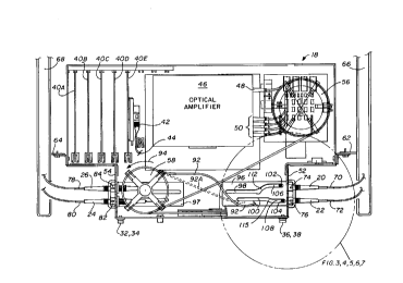
Referring now to FIG. 2 and FIG. 3, there is shown a top view of panel
18, which illustrates the apparatus of this invention. As shown, a support
structure such as panel 18 may contain a number of printed circuit boards,
such as boards 40A-40E. As can be seen, there is a fiber-optical connector
42 attached to optical fiber 44, which is mounted to one of the printed
circuit
boards, such as board 40E. There is also shown amplifier circuitry 46 having
a single input optical fiber 48 and four optical outputs indicated by
reference
number 50. In the particular embodiment shown, the four optical outputs are
DL: 1055148v1
560043-610080
CA 02319936 2000-09-20
connected to optical fiber cables which terminate two each at side panels 28
and 30 by means of attachment members 52 and 54. It should be noted at
this point that the routing of the optical fiber cables between the outputs 50
and the attachment members 52 and 54 is simplified for purposes of
5 explanation but, as shown in the embodiment of FIG. 2, are coiled around a
first spool area 56, having a minimum diameter such that the transmission
qualities of the fiber optics will not be degradated. The optical fiber then
travels from the spool 56 to a pair of spools 58 and 60 (not shown), which
also have a diameter that is large enough to prevent degradation of the
transmission quantities of the fiber optics. Spool 60 has not been included
to avoid difficulty in reviewing and understanding the drawings. If spool 50
had been included, it would be located over cam plate 96 in the same manner
spool 58 is located over cam plate 97. Shown for illustration purposes only
and to help the understanding of the present invention, it is seen that the
panel 18 is mounted by brackets 62 and 64 to the edges 66 and 68,
respectively, of cabinet 10. It is also seen that a pair of cables 70 and 72
terminate at connectors 20 and 22, respectively, and are, in turn, connected
to bulkhead connectors 74 and 76 which are mounted to attachment member
52 of side panel 30. Likewise, cables 78 and 80 terminate at optical
connectors 24 and 26 which connectors are, in turn, connected to bulkhead
connectors 82 and 84 which are mounted to attachment member 54. As was
discussed earlier with respect to FIG. 1, the optical fiber connectors 20, 22,
24, and 26 are somewhat delicate and must be protected from sharp or small
radius bends in the same manner the optical fibers 70, 72, 78, and 80 are
protected. It is also important to avoid excessive tension on the cables
since,
if a loop of the cable exists and is subjected to tension, the radius of the
loop
will likely be reduced below a satisfactory level. The arrangement of the
DL: 1055148x1
560043-610080
CA 02319936 2000-09-20
6
cables coming from the side areas 66 and 68 of cabinet 10 to the side
attachment members 52 and 54 helps prevent such excessive small radius
loops. It will be readily appreciated, that, for example, the optical fibers
70
and 72 and their respective connectors 20 and 22 will be protected from
unintentional forces and are protected from impact in a much superior
manner than they would be if mounted on the front face 82 of panel 18.
However, it will be appreciated that if side panels or attachment
members 52 and 54 on side panels 30 and 28, respectively, were simply
rigidly fixed panels at the side of panel 18, they would create their own
shortcomings. Therefore, panels 52 and 54 include the novel and inventive
apparatus and methods of the present invention. For example, as shown,
side panel 30 or attachment member 52 includes bulkhead optical fiber
connectors 74 and 76, such that optical fibers can be mounted to the
connector on both sides of attachment member 52. Thus, in the embodiment
shown, fiber-optical connectors 20 and 22 are connected to bulkhead
connectors 74 and 76, respectively, while at the same time fiber-optical
connectors 88 and 90 (see FIG. 3) connect to the back side of bulkhead
connectors 74 and 76. An optical fiber is, of course, attached to each of the
connectors 88 and 90. For example, optical fibers 92 and 93 are shown
connected to side panel 52 at connectors 88 and 90. In the embodiment
shown, it is seen that the optical fiber cable 92 is routed around spool 58
and
then to spool 56 before being connected to one of the outputs 50. It is also
seen that optical fiber cable 92 is of an excessive length for purposes as
will
be discussed later. However, it is important to notice that there is not a
full
loop of optical fiber cable 92, thereby avoiding the possibility of tight
kinks or
short radius loops. In another embodiment, rather than having an excessive
amount of loose fiber-optic cable as discussed above, the spool or reel 58 is
DL: 1055148v I
560043-610080
CA 02319936 2000-09-20
biased to rotate in the direction shown by arrow 94 to keep the fiber-optic
cable wound around reel 58 as indicated by the straight dotted lines 92A.
Although biased in the direction indicated by arrow at 94, it will be
appreciated that spool 58 must be allowed to rotate in the direction opposite
arrow 94 to allow side panel or attachment member 52, with the cables
attached, to be moved away from panel 18. Therefore, it will be appreciated
that spool 58 will have a limited amount of travel in a clockwise direction of
between about 90° and 180°.
As shown, a cam plate 96 is secured to side panel or attachment
member 52 on side panel 30. Also as shown, cam plate 96 defines two cam
tracks (98 and 100), which have a shape that controls the amount and
direction of movement of side panel or attachment member 52. In each cam
track 98 and 100, there is located cam followers 102 and 104, respectively,
which are rigidly secured to panel 18 such that, when the attachment member
52 is pulled away from panel 18 as discussed above, the amount of
movement away from and the direction of movement is controlled.
Referring now to FIGS. 3-7, there is shown the movement of side panel
or attachment member 52 with the optical fiber cables 70 and 72 attached on
the outside face of attachment member 52 and cable 92 attached to
connector 90 on the inside face of attachment member 52. As shown in FIG.
3, the position of the attachment member 52 is the same as was discussed
with respect to FIG. 2 above and the attachment member 52 is secured in
position for normal operation by quick-disconnect members or screws 36 and
38. However, in FIG. 2 and FIGS. 4-7, the optical connectors 88 and 90 and
optical fiber 92 are not shown so that the cam tracks 98 and 100 are clearly
visible. FIG. 3, however, shows fibers 92 and 93 as well as connectors 88
and 90, even though the cam tracks 98 and 100 are obscured. Referring to
DL: 1055148v1
560043-610080
CA 02319936 2000-09-20
g
FIG. 4, there is shown the first allowable movement of attachment member
52. It will be appreciated by those skilled in the art, maintenance of fiber-
optical cables often requires the interface between the cable and the
bulkhead connector to be cleaned. This is because anytime the optical fiber
cable connectors are exposed, it is possible for dirt to be admitted and, when
reconnected, the efficiency of the fiber-optical transmission will suffer. As
shoinrn in FIGS. 2 and 4, the initial portions 106 and 108 of cam tracks 98
and
100, respectively, are parallel to each other and extend perpendicular to the
inside face of attaching member 52. Thus, the initial movement allowed by
the cam tracks of attaching member 52 away from 18 is directly away from
panel 18 as shown by arrow 110 in FIG. 4.
After the first movement of attachment member 52, it is seen in FIG. 5
that no further movement is allowed except for rotational movement due to
the curved portion 112 of cam track 98 and the abrupt stop or direction
change of cam track 100. Thus, the cam followers 102 and 104 only allow
the rotational movement as indicated by double-headed arrow 113 in FIG. 5.
The rotation of the attachment member continues until the full length of the
curved portion 112 of the path 98 is traversed and no further rotational
motion
is possible.
Referring now to FIG. 6, it is seen that the small path segment 115 of
track 100 requires the next motion of the attachment member 52 to be a slight
motion towards the front of the panel 18 as indicated by arrow 114. Once
the cam plate 96 has made the small movement allowed by path segment
115 of cam track 100 as illustrated in FIG. 6, the remaining length of both
cam tracks 98 and 100 is parallel to each other and allows the final full
extension of the attachment member 52 at approximately a 45° angle away
from the edge 66 of the cabinet 10.
DL: 1055148v1
560043-6(0080
CA 02319936 2000-09-20
9
FIG. 7 shows the attachment member 52 in its fully extended position
with the cam follower pins 102 and 104 at the end points of cam tracks 98
and 100, respectively. Thus, it will be appreciated that the direction of
movement and the degree of movement have been controlled by the cam
tracks and the cam followers according to the teachings of the present
invention. Also, it will be appreciated that in this fully extended position,
the
fiber-optical cables connected to both sides of the bulkhead optical
connectors 74 and 76 are easily accessed for maintenance purposes.
The corresponding structures; materials, acts, and equivalents of all
means or step plus function elements in the claims below are intended to
include any structure, material, or act for performing the function in
combination with other claimed elements as specifically claimed.
DL: 1055148v1
560043-610080