Note: Descriptions are shown in the official language in which they were submitted.
CA 02320036 2000-08-10
GR 98 P 3080 P
1
Description
' High-temperature fuel cell and stack of high-
temperature fuel cells
The invention relates to a high-temperature fuel cell
with at least one interconnector plate and with an
electrolyte/electrode unit, and also to a stack of
high-temperature fuel cells formed from high-
temperature fuel cells of this type.
It is known that when water is electrolyzed the
electrical current breaks down the water molecules into
hydrogen (H2) and oxygen (OZ). A fuel cell reverses this
procedure. Electrochemical combination of hydrogen (HZ)
and oxygen (Oz) to give water is a very effective
generator of electricity. This occurs without any
emission of pollutants or carbon dioxide if the fuel
gas used is pure hydrogen (Hz). Even with an industrial
fuel gas, such as natural gas or coal gas, and with air
(which may also have been enriched with oxygen (02))
instead of pure oxygen (Oz) a fuel cell produces
markedly less pollutants and less carbon dioxide than
other energy generators in which the energy is
introduced from different sources. The fuel cell
principle has been implemented industrially in various
ways, and indeed with various types of electrolyte and
with operating temperatures of from 80°C to 1000°C.
Depending on their operating temperature, fuel cells
are divided into low-, medium- and high-temperature
fuel cells, and these in turn have a variety of
technical designs.
In the case of a stack of high-temperature fuel cells
composed of a large number of high-temperature
CA 02320036 2000-08-10
GR 98 P 3080 P
2
fuel cells, there is an upper interconnector plate
which covers the stack of high-temperature fuel cells,
' and under this plate there are, in this order, at least
one protective layer, one contact layer, one
electrolyte/electrode unit, one further contact layer,
one further interconnector plate, etc.
The electrolyte/electrode unit here comprises two
electrodes - one anode and one cathode - and a solid
electrolyte designed as a membrane arranged between
anode and cathode. Each electrolyte/electrode unit here
situated between two adjacent interconnector plates
forms, with the contact layers situated immediately
adjacent to the electrolyte/electrode unit on both
sides, a high-temperature fuel cell, which also
includes those sides of each of the two interconnector
plates situated on the contact layers. This type of
fuel cell, and other types, are known from the "Fuel
Cell Handbook" by A. J. Appleby and F. R. Foulkes,
1989, pp. 440-454, for example.
A single high-temperature fuel cell provides an
operating voltage of less than one volt. A stack of
high-temperature fuel cells is composed of a large
(~ 25 number of high-temperature fuel cells. The connection
in series of a large number of adjacent high-
temperature fuel cells can give an operating voltage of
some hundreds of volts from a fuel-cell system. Since
the current provided by a high-temperature fuel cell is
high - up to 1000 amperes in the case of large high-
temperature fuel cells - the electrical connection
between the individual cells should preferably be one
which gives rise to particularly low series electrical
resistance under the abovementioned conditions.
CA 02320036 2000-08-10
05-26-2000 PCT/DE99/00206 DESC
GR 98 P 3080 P
PCT/DE 99/00206
3
The electrical connection between two high-temperature
fuel cells is provided by an interconnector plate, via
which the anode of one high-temperature fuel cell is
connected to the cathode of the next high-temperature
fuel cell. The interconnector plate therefore has an
electrical connection to the anode of a high-
temperature fuel cell and to the cathode of the next
high-temperature fuel cells. The electrical connection
between the anode and the interconnector plate is
provided by an electrical conductor which may take the
( form of a nickel grid (see, for example, DE 196 49 457
C1) . It has been found here that the series electrical
resistance between nickel grid and interconnector plate
is high, at some hundreds of mOhm cm2. This has a severe
adverse effect on the electrical performance of the
stack of high-temperature fuel cells.
It is an object of the invention to improve a high-
temperature fuel cell of the type mentioned at the
outset so as to avoid any relatively high series
electrical resistance and to ensure high conductivity,
even over prolonged periods. A further object of the
invention is to improve a stack of the type mentioned
at the outset of high-temperature fuel cells so as to
avoid any relatively high series electrical resistance
and to ensure high conductivity, even over prolonged
periods.
The first object mentioned is achieved by way of a
high-temperature fuel cell of the type mentioned at the
outset in which, according to the invention, a layer
comprising chromium carbide CrxCy for lowering the
series electrical resistance of the high-temperature
fuel cell has been arranged on that side of the
AMENDED SHEET
Printed: 06.06.2000
CA 02320036 2000-08-10
05-26-2000 PCT/DE99/00206 DESC
GR 98 P 3080 P
PCT/DE 99/00206
3a
interconnector plate which faces toward the anode of
the electrolyte/electrode unit.
Experiments with a stack of high-temperature fuel cells
and appropriate modeling experiments have shown that,
even after a short period of operation, an oxide layer
AMENDED SHEET
Printed: 06.06.2000
CA 02320036 2000-08-10
GR 98 P 3080 P
4
forms between a nickel grid and an interconnector plate
composed of CrFe5Y3031. An oxide layer develops here on
the surface of the side of the interconnector plate
which faces toward the space through which the fuel gas
passes in the high-temperature fuel cell, which layer
is probably composed of a CrNi spinel where the nickel
grid and interconnector plate are in cohesive contact,
and of Cr203 where they are in non-cohesive contact.
If, for example, an electron-beam welding process has
been used to give the nickel grid nine points of
contact with the interconnector plate, these welded
contact points then form only a fraction (<0.1~) of the
total number of contact points which connect the nickel
grid electrically to the interconnector plate. The
majority of the contact points are pressure contacts
arising where the nickel grid presses onto the
interconnector plate. These pressure contacts are
situated on the oxide layer which forms during
operation of the high-temperature fuel cell and as
operation continues grows into the interconnector plate
in compliance with a parabolic function.
There is therefore a poorly conducting oxide layer
between the nickel grid and the interconnector plate,
and this has an adverse effect on the series resistance
of high-temperature fuel cells connected in series. The
chromium oxide forms even when the partial pressure of
oxygen is about 10-la bar. These partial pressures of
oxygen are always present during normal operation of
the high-temperature fuel cell.
The invention is based on the idea that suppressing the
formation of the oxide layer on the interconnector
plate avoids any relatively high series electrical
resistance and ensures high conductivity even over
prolonged periods. This is reliably achieved during the
CA 02320036 2000-08-10
GR 98 P 3080 P
4a
operation of the high-temperature fuel cell by the
' arrangement on the interconnector plate of a means of
CA 02320036 2000-08-10
OS-26-2000 PCT/DE99/00206 DESC
- GR 98 P 3080 P
PCT/DE 99/00206
preventing oxidation of the interconnector plate. Such
a means of preventing oxidation of the interconnector
plate is therefore a means of lowering the series
electrical resistance during the operation of the high-
s temperature fuel cell below that of a cell which does
not comprise this means.
A protective layer of chromium carbide CrXCy does not
oxidize under operating conditions; it is therefore
oxidation-resistant. A 'layer of this type should be
gas-tight when applied, so as to be impermeable to
oxygen. Comprehensive experimentation has shown that
oxidation of the interconnector plate is reliably
prevented to a very large extent by a layer of chromium
carbide CrXCy. It is also cost-effectiven and easy to
handle.
It is advantageous to use chromium carbide Cr3C2, CrC,
Cr~C3, or Cr23C6. A layer which comprises one or more of
these compounds is highly electrically conducting. This
means that the layer causes no, or only insignificant,
impairment of the electrical connection between anode
and interconnector plate. A layer of this type is
i
usually very resistant to corrosion at the partial
pressures of oxygen usually prevailing on the fuel-gas
side of the interconnector plate during operation of
the high-temperature fuel cell. It is moreover
chemically resistant to the operating media which pass
over the fuel-gas side of the interconnector plate
during operation - for example methane or gases derived
from carbon.
An appropriate thickness for the layer is from 5 um to
10 Eun. A chromium carbide layer of this thickness is
AMENDED SHEET
Printed: 06.06.2000
CA 02320036 2000-08-10
05-26-2000 PCT/DE99/00206 DESC
GR 98 P 3080 P
PCT/DE 99/00206
5a
particularly effective in preventing oxidation of the
fuel-gas side of the interconnector plate.
AMENDED SHEET
Printed: 06.06.2000
CA 02320036 2000-08-10
GR 98 P 3080 P
6
In another advantageous embodiment of the invention, a
nickel grid has been arranged between the
interconnector plate and the anode of the
electrolyte/electrode unit and has been connected
electrically to the interconnector plate. The nickel
grid may also be a nickel grid package which comprises
a relatively thin contact grid and a relatively thick
carrier grid. The material nickel is particularly
advantageous, since it does not oxidize at the partial
pressures of oxygen usually prevailing on the fuel-gas
side during operation of the high-temperature fuel
cell. Nickel is moreover cost-effective and easy to
l
handle. A grid manufactured from nickel is flexible
and, even if simply situated on the interconnector
plate, ensures sufficient electrical contact between
interconnector plate and nickel grid. This contact is
retained even during temperature variations within the
high-temperature fuel cell.
A thin chromium carbide layer is electrically
conductive, and the initial conductivity of the
composite of interconnector plate plate/chromium
carbide layer/nickel grid is therefore practically
retained for the entire period of operation. This
(: 25 electrical conductivity of the chromium carbide layer
means that even the mechanical contact produced by
lying against the chromium carbide layer connects the
nickel grid to the interconnector plate plate. A better
electrical and mechanical connection between nickel
grid and connector plate plate is achieved by welding
the nickel grid onto the interconnector plate plate.
Spot welding is an appropriate process for this. In
cases where the nickel grid has been point-attached to
the interconnector plate plate the spot welds extend
through the chromium carbide layer and connect the
nickel grid to the interconnector plate plate.
CA 02320036 2000-08-10
GR 98 P 3080 P
6a
Cost-effective processes can be used to coat the
' interconnector plate plate with a thin chromium carbide
layer. The coating may take place by a
l
CA 02320036 2000-08-10
GR 98 P 3080 P
7
PVD (physical vapor deposition) process, for example. A
process of this type is sputtering - for example in
pure argon, electron-beam vapor deposition or laser-
beam vapor deposition. These processes can be used to
coat one side of the interconnector plate. The coating
temperature is below S00°C.
An alternative to the PVD process is a CVD process
(chemical vapor deposition). In this thermal coating
process the substance to be coated is produced in the
gas phase by the chemical decomposition of starting
materials and applied to the component to be coated.
E
In another advantageous embodiment of the invention,
the interconnector plate consists of CrFe5Yz031, i.e. of
94~ by weight of chromium, 5~ by weight of Fe and 1~ by
weight of Yz03. An interconnector plate of this type has
proven in numerous experiments to be suitable for
operation in an high-temperature fuel cell. It can also
easily be coated with a chromium carbide layer.
The second object mentioned is achieved by means of a
stack of the type mentioned at the outset of high-
temperature fuel cells which comprises high-temperature
fuel cells in which according to the invention a means
for lowering the series electrical resistance of the
high-temperature fuel cell has been arranged on that
side of the interconnector plate which faces toward the
anode of the electrolyte/electrode unit.
To avoid repetition, for the description of other
embodiments and advantages of the invention reference
is made to the statements made above.
Examples of the invention are described in more detail
below using two figures, in which
CA 02320036 2000-08-10
GR 98 P 3080 P
8
FIG. 1 shows a diagram of a section of a high-
temperature fuel cell;
FIG. 2 shows a detailed diagram of a section of a high-
s temperature fuel cell;
Fig. 1 shows a diagram of a section of an
interconnector plate 12 of a high-temperature fuel
cell 11. The surface 14 of the fuel-gas side of the
interconnector plate 12 - i.e. that surface which faces
toward the anode 16 of the electrolyte/electrode
unit 17 of the high-temperature fuel cell 11 - has been
coated with a layer 15 of chromium carbide CrzC3. The
interconnector plate 12 has been electrically connected
to the anode 16 by an electrical conductor not shown in
the figure. The intervening space between the anode 16
and the layer 15 is a section of the fuel gas space of
the high-temperature fuel cell 11. The layer 15
effectively and reliably prevents oxidation of the
fuel-gas side of the interconnector plate 12 during
operation of the high-temperature fuel cell 11.
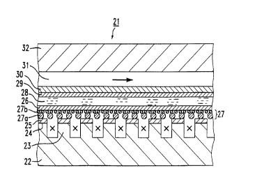
Figure 2 shows a detailed diagram of a section of a
high-temperature fuel cell 21. An interconnector
plate 22 of CrFe5Yz031 has been provided with a number
of protuberances 23, between which have been formed
channels running perpendicularly to the plane of the
paper for operating media. These channels are supplied
with a fuel gas, such as hydrogen, natural gas or
methane. The surface 24 of the interconnector plate 22
has been provided with a thin layer 25 of chromium
carbide CrC, of about 10 ~.m thickness. The layer 25 has
been applied by a PVD process. The nickel grid 27 has
been connected electrically and mechanically to the
interconnector plate 22 by spot welds which extend
through the layer 25 of chromium carbide. For clarity
CA 02320036 2000-08-10
GR 98 P 3080 P
8a
the spot welds are not shown in the figure. The nickel
' grid 27 here is a nickel grid package consisting of a
CA 02320036 2000-08-10
GR 98 P 3080 P
9
coarse, relatively thick nickel carrier grid 27a and of
' a fine, relatively thin nickel contact grid 27b.
Adjacent to the nickel grid 27 is is a thin anode 26,
on the far side of which is a solid electrolyte 28.
This solid electrolyte 28 has a cathode 29 on its upper
side. The cathode 29 is adjoined by a contact layer 30
and another interconnector plate 32, only the lower
part of which is shown. A number of channels 31 for
operating media have been made in the interconnector
plate 32, but only one of these is shown. The channels
31 for operating media run parallel to the plane of the
paper, and oxygen or air passes through these during
operation of the high-temperature fuel cell 21.
The unit consisting of cathode 29, solid electrolyte 28
and anode 26 is termed the electrolyte/electrode unit.
The layer 25 of chromium carbide shown in Figure 2
prevents damaging oxidation of the interconnector
plate 22 lying beneath the same during operation of the
high-temperature fuel cell 21. In particular, corrosion
below the surface of the spot welds is also suppressed.
This gives the high-temperature fuel cell 21 low series
resistance which increases only insignificantly, or not
at all, as the period of operation continues.
A number of these high-temperature fuel cells 21 may be
brought together to give a stack of fuel cells or
"stack".