Note: Descriptions are shown in the official language in which they were submitted.
CA 02320231 2000-08-08 CA 009900084
14-03-2000
' = = = = == .... =. =.
.. .= .. = . . . = .. .
=.. = =. . . . = =. .
= = = =... = = = = = = == .
= . . . . = = . = = . .
= . === = =. .. =. ..
AUTOMOTIVE SEAT ASSEMBLY HAVING
A RETRACTABLE HEADREST
Technical Field
The subject invention relates to automotive seat assemblies which include
adjustable or retractable headrests.
Background of the Invention
Front and rear seats in many passenger vehicles, such as automobiles, include
respective headrests which provide added comfort for a passenger. In addition
to the
comfort feature, the headrests also provide a safety feature. Namely, the
headrests provide
needed head support during rear end collisions which reduces the likelihood of
whiplash
type injuries. Headrests are typically mounted to a top portion of a seat back
as either an
integral part of the seat back or as a separate unit mounted to the seat back.
The separable
headrests usually include some type of height adjustment mechanism. One of the
deficiencies which occurs when having a headrest is the possibility of
obstructed views for
the driver and/or passengers. Another deficiency occurs when the seat is
folded
downwardly to provide added storage space. Specifically, the headrest
protruding from the
top portion of the seat back extends the length of the seat back; therefore,
the amount of
available storage space is reduced.
The prior art has contemplated some solutions to these deficiencies. One
relatively
simple solution is to remove the headrest from the seat back when views are
obstructed
and/or the seat back is folded downwardly. This solution, however, creates
another
problem of what to do with the loose headrest Another solution relates to
having the
headrest move to a position behind the seat back. An example of this type of
headrest is
disclosed in United States Patent No. 4,935,680. Some difficulties encountered
with these
designs are that the height adjustment means may be exposed and the headrest
is still
occupying a portion of the needed cargo space.
French Patent No. 2 432 855 discloses another solution which conceals the
headrest
into a portion of the seat back when the seat back is folded forward. The
headrest has an
elongated frame which is pivotally connected to a bottom of the seat assembly.
The
headrest frame abuts a top portion of a seat back frame and also extends
upwardly beyond
the seat back frame. As the seat back is pivoted to the folded position, the
seat back frame
pushes against the headrest frame to also pivot the headrest frame downward.
The seat
back slides over the headrest such that the headrest is at least partially
concealed within the
seat back. This proposed solution, however, creates a headrest which has no
adjustment
-2-
AMENDED SHEET
CA 02320231 2000-08-08
14-03-2000 CA 009900084
= . . . =. .... .. .~
.. .. .= . . . = . . . .
. . . = . . . . . . . = .
. . . =..= . . . . = = =. .
= = = . = .. = . .= .
= = =.. . .. =. == ..
capabilities when the seat back is in the seating position. In addition, the
headrest frame
occupies a significant amount of space within the seat back. The headrest
frame therefore
reduces the available space for added components such as lumbar supports,
heating
elements and the like.
Yet another solution contemplated by the prior art is shown in German Patent
No.
197 27 097. The German'097 patent discloses a seat assembly having a headrest
which
adjusts when the seat is moved forward or rearward and retracts when a seat
back is pivoted
downward to a folded position. A first cable is used to pull the headrest
upward toward an
extended position and a second cable is used to pull the headrest downward
toward a
retracted position. A guide is also utilized which directs the headrest
through the upward
and downward movements. One deficiency of this design, is that the guide and
cable
arrangement extend into the seat back occupying a significant portion of the
seat back. In
addition, the double cable arrangement requires a number of directional
pulleys and guides.
Finally, the first cable is continuously tensioned when the seat back is in
the seating
position and the headrest is in the extended position. This continuous strain
on the cable
reduces the effective operating life of the adjustment mechanism.
Hence, there is a need for a headrest design which can provide adequate
support for
a passenger and yet be automatically retracted to improve the viewing area and
increase the
available storage space, while overcoming the deficiencies outlined above.
Primarily, the
adjustable headrest mechanism should be of a simple design which occupies only
a small
area of the seat back.
30
-la-
AMENDED SHEET
CA 02320231 2000-08-08 CA 009900084
14-03-2000
. . . . .. .... .. .$
.. .. .. . . . . . . . .
==. . .. . . . . .. .
. . . .... . . . . . . . . .
= . . . . .. . . .. .
. . ... . .. .. .. ..
Summary of Invention and Advantages
An automotive seat assembly comprising a seat cushion and a seat back, having
top
and bottom portions, pivotally mounted to the seat cushion for movement
between a seating
position and a folded position. A headrest is mounted to the top portion of
the seat back
and moveable between a deployed position and a retracted position. A control
mechanism
is supported by the seat back and is operatively connected to the headrest for
automatically
moving the headrest toward the retracted position in response to the pivotal
movement of
the seat back toward the folded position. The subject invention is
characterized by the
control mechanism fnrther including a biasing device supported by the seat
back and
operatively coupled to the headrest for continuously biasing the headrest
toward the
deployed position.
Accordingly, the headrest of the subject invention can provide adequate
support for
a passenger and be retracted to improve the viewing area and increase the
available storage
space in a vehicle. The headrest is automatical2y retracted in response to the
movement of
the seat back. The headrest may be retracted into a cavity in the seat back or
behind,
beside, or in front of the seat back. The control mechanism is of a compact
and relatively
inexpensive design. As an added feature, the control mechanism does not have a
cable
which is stressed or tensioned when the headrest is in the fully extended
position, thereby
extending the operating life of the mechanism. Finally, the control mechanism
also
includes a stop for locking the headrest in the extended position until the
seat back is folded
forward.
Brief Description of the Drawings
Other advantages of the present invention will be readily appreciated as the
same
becomes better understood by reference to the following detailed description
when
considered in connection with the accompanying drawings wherein:
Figure 1 is a perspective view of front and rear seat assemblies incorporating
a
headrest in accordance with the subject invention;
Figure 2 is a schematic view of the headrest in a deployed position relative
to a seat
back;
Figure 3 is a schematic view of the headrest in a retracted position relative
to the
seat back;
-2-
AMENDED SHEET
CA 02320231 2000-08-08
WO 99/41104 PCT/CA99/00084
Figure 4 is a partially cross-sectional side view of the seat back
incorporating
the headrest of the subject invention;
Figure 5 is a schematic side view of the seat assembly with the seat back is a
seating position, partially folded position, and a fully folded position;
Figure 6 is a partially cross-sectional rear view of the seat back with the
headrest in the deployed position;
Figure 7 is a partially cross-sectional rear view of the seat back with the
headrest in a partially retracted position; and
Figure 8 is a partially cross-sectional rear view of the seat back with the
headrest in the fully retracted position.
Detailed Description of the Preferred Embodiment
Referring to the Figures, wherein like numerals indicate like or corresponding
parts throughout the several views, an automotive seat assembly is generally
shown
at 10 in Figure 1. The seat assembly 10 comprises a front row seat 12 and a
rear row
seat 14. Both of the front 12 and rear 14 row seats include a seat cushion 16
and a
seat back 18. Each of the seats 12, 14 are of a conventionally known
construction
which includes a seat frame, a flexible foam pad and a trim cover material. As
also
shown in Figure 5, the seat back 18 has top 20 and bottom 22 portions and is
pivotally mounted to the seat cushion 16 for movement between a seating
position and
a folded position. As appreciated by those skilled in the art, the seat back
18 is in a
seating position when the seat back 18 is upright and substantially
perpendicular to
the seat cushion 16. The seat back 18 is in the folded position when the seat
back 18
is pivoted forward toward the seat cushion 16 to at least partially overlay
the seat
cushion 16. In some applications the seat cushion 16 may pivot upwardly and
forwardly along with the seat back 18 to create what is known in the artas a
tumbled
seat. In other applications, the seat cushion 16 may pivot upwardly and
forwardly
independently of the seat back 18 such that the seat back 18 may fold downward
abutting an underside of the seat cushion 16.
3
CA 02320231 2000-08-08
WO 99/41104 PCT/CA99/00084
Referring also to Figures 2 and 3, a headrest 24 is mounted to ihe top portion
20 of the seat back 18 and is moveable between a deployed position and a
retracted
position. A control mechanism, generally shown at 26, is mounted between the
seat
back 18 and the headrest 24 for moving the headrest 24 between the deployed
and
retracted positions. Preferably, the seat assembly 10 includes a cavity 28
formed
within the top portion 20 of the seat back 18 for selectively housing the
headrest 24.
The control mechanism 26 moves the headrest 24 between the deployed position
with
the headrest 24 substantially disposed outside of the cavity 28 and the
retracted
position with the headrest 24 substantially disposed within the cavity 28.
Even more
preferably, the headrest 24 is disposed completely outside of the cavity 28
when in
the deployed position and disposed completely within the cavity 28 when in the
retracted position. As appreciated, the headrest 24 may only be partially
deployable
and/or partially retractable without deviating from the overall scope of the
subject
invention. It is only necessary that some retraction take place in orderto
provide the
desired retracting effect. As also appreciated, the control mechanism 26 may
be of
any suitable design or configuration without deviating from the general scope
of the
invention. As discussed below, the preferred design of retracting the headrest
24 is
to link the headrest 24 with the pivotal movement of the seat back 18. The
subject
invention, however, is not limited to this particular linking design. The
passenger
may be able to retract the headrest 24 in any suitable manner irrespective of
the
position of the seat back 18.
Referring back to Figure 5, the control mechanism 26 preferably moves the
headrest 24 automatically between the deployed and retracted positions in
response
to the pivotal movement of the seat back 18 between the seating and folded
positiors.
Hence, the movement of the headrest 24 is linked to the pivotal movement of
the seat
back 18. This provides a user friendly design in that a passenger only has to
pivot
the seat back 18 forward in order to retract the headrest 24. As appreciated,
the
cavity 28 formed within the seat back 18 may be eliminated such that the
headrest 24
moves or retracts to a position overlying the front, side or rear of the seat
back 18.
4
CA 02320231 2000-08-08 CA 009900084
14-03-2000
= . = . .. =... .. .,
.. .. .. . . . . . . . .
... . .. . . . . .. .
. . . .... . . . . . . . . .
= ~ = = . .. . . .. .
= . ... . .. .. .. . ~
The subject invention is not necessarily limited to automaticaIly retra.cting
the headrest 24,
in response to movement of the seat back 18, into the cavity 28. It should
also be appreciated, the deployment and/or retraction positions of the
headrest 24 do not
necessarily have to occur at the maximum seating and/or folding positions of
the seat back
18.
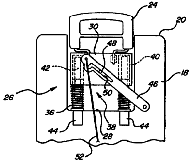
Referring also to Figures 4 and 6 through 8, the control mechanism 26 further
includes a moveable mounting plate 30 with the headrest 24 fixedly secured to
the
mounting plate 30. Specifically, the headrest 24 includes a pair of headrest
posts 32 which
are mounted to the plate 30. The headrest 24 shown is designed with a
passageway 34 and
may be covered by a trim cover material such as cloth, leather or vinyl. As
appreciated, the
headrest 24 may be of any suitable design or configuration. The control
mechanism 26 also
includes a biasing device 36 disposed within the cavity 28 between the
mounting plate 30
and the seat back 18 for continuously biasing the headrest 24 between the
retracted and
deployed positions. The biasing device 36 may continuously bias the headrest
24 toward
the retracted or deployed positions depending upon the particular
configuration of the
control mechanism 26. The control mechanism 26 also includes an actuation
device,
generally shown at 38, mounted between the seat back 18 and the mounting plate
30 for
selectively moving the mounting plate 30 and the headrest 24 toward the
retracted position
and into the cavity 28. As discussed above, the actuation device 38 may be a
separate
manual or power device or may be interconnected with the movement of the seat
back 18.
The preferred embodiment of the control mechanism 26 is now discussed in
greater
detail. At least one socket 40 is formed within the mounting plate 30 and at
least one guide
post 42 extends outwardly from the socket 40. Preferably, the post 42 is
fixedly mounted
to the mounting plate 30 at one end and extends outwardly to a distal second
end. For
example, the post 42 may be welded, bolted, press fit or the like to the
mounting plate 30.
The control mechanism 26 further includes at least one hollow support tube 44
mounted within the cavity 28 and extending upwardly toward the top portion 20
of the seat
back 18. A collar (not numbered) securely mounts the support tube 44 to the
frame of the
seat back 18. Preferably, there are a pair of sockets 40, posts 42 and
corresponding
-5-
AMENDED SHEET
CA 02320231 2000-08-08
WO 99/41104 PCT/CA99/00084
support tubes 44. The guide posts 42 are aligned with and slideably engage the
support tubes 44 for supporting the headrest 24 and guiding the headrest 24
between
the retracted and deployed positions relative to the cavity 28. Preferably,
the guide
posts 42 have a diameter smaller than an inner diameter of the sockets 40 such
that
the support tubes 44 may also extend into the sockets 40 when the headrest 24
is
moved into the retracted position within the cavity 28 (Figures 7 and 8). The
biasing
device 36 is a coil spring 36 disposed around each of the support tubes 44
with a first
end engaging the cavity 28 of the seat back 18 and a second end engaging the
mounting plate 30 such that the mounting plate 30 and the headrest 24 are
continuously biased toward the deployed position. The coil springs 36 encircle
the
tubes 44 in a helical manner as is known in the art. The biasing devire 36 may
be of
any suitable design and may be positioned independent of the tubes 44.
The actuation device 38 further includes an actuation lever 46 pivotally
mounted to the seat back 18. A limit pin 48 extends from the mounting plate 30
and
slideably engages the lever 46 such that the lever 46 is movably mounted to
the
mounting plate 30. The lever 46 includes an integral L-shaped slot 50 with the
limit
pin 48 slideably disposed within the slot 50. The slot 50 is constructed to
include an
elongated portion and a recessed stop (not numbered). When the headrest 24 is
in a
deployed position, the limit pin 48 engages the recessed stop of the lever 46
which
locks the headrest 24 in place. During the retracting and semi deployed
movements
of the headrest 24 the limit pin 48 slides within the elongated portion of the
slot 50.
The actuation device 38 further includes a remote control cable 52 having a
first end mounted to the lever 46 and a second end mounted to the bottom
portion 22
of the seat back 18 such that pivotal movement of the seat back 18 toward the
folded
position tensions the cable 52 to move the lever 46 and the mounting plate 30
toward
the retracted position against the biasing force of the biasing device 36. As
discussed
above, the second end of the cable 52 may be mounted to an alternative device,
such
as a handle (not shown), in order to provide a retracting feature for the
headrest 24
6
CA 02320231 2000-08-08
WO 99/41104 PCT/CA99/00084
without the pivoting of the seat back 18. The remote control cable 52 is of
any
suitable design such as a Bowden cable assembly having a surrounding conduit.
Preferably the cable 52 is mounted to the lever 46 at an opposite end from ttu
pivot point and adjacent the recessed stop of the slot 50. The cable 52 may be
fastened to the lever 46, seat back 18 and/or alternative device by any
suitable cable
fastener. As discussed above, the second end of the cable 52 is mounted to the
bottom portion 22 of the seat back 18 and more preferably to a cable
retracting
mechanism (not shown) mounted to the bottom portion 22 of the seat back 18.
The
cable retracting mechanism retains the second end of the cable 52 in a fixed
position.
As the seat back 18 is pivoted forward toward the folded position the lever 46
moves
downward due to the tensioning in the cable 52.
The preferred operation of the headnest 24 includes an automatic deployment
and retraction based upon the position of the seat back 18 with the headrest
24
retracting into the cavity 28 formed within the seat back 18. When the
headrest 24
is fully deployed (Figures 2,4,6) it is completely extended to the maximum
limit
allowed by the lever 46 and limit pin 48. As shown in Figure 5, the headrest
24 is
in a fully deployed position when the seat back 18 is in a fully upright
seating
position. As the seat back 18 is pivoted forwardly toward a folded position,
the cabb
52 tensions which pulls the lever 46 downwardly. The initial downward movement
of the lever 46 disengages the limit pin 48 with the recessed stop of the slot
50. The
limit pin 48 is subjected to a downwardly directed canaming action by the
elongated
portion of the slot 50. The downward pulling force of the lever 46 overcomes
the
upward biasing force of the springs 36. This pulls the plate 30 downward which
compresses the springs 36 and pulls the entire headrest 24 downward into the
cavity
28. Specifically, the guide posts 42 telescopingly engage the tubes 44 as the
headre.st
24 moves into the cavity 28. The retracting action of the headrest 24
continues until
the seat back 18 is completely folded. In this position (Figure 8) the springs
36 are
completely compressed and the headrest 24 is completely retracted into the
cavity 28.
As appreciated, the dimensions of the cavity 28, size of the springs 36,
length of the
7
CA 02320231 2000-08-08
WO 99/41104 PCT/CA99/00084
cable 52, and total pivoting angle of the seat back 18 must all be
appropriately
coordinated to ensure a desired retraction of the headrest 24. As the seat
back 18 is
gradually pivoted rearward back to the seating position, the cable 52
gradually
slackens which allows the springs 36 to automatically lift the headrest 24 out
of the
cavity 28. This upward deployment movement continues until the limit pin 48
returns
into the recessed stop of the slot 50 thereby locking the headrest 24 in the
deployed
position.
The invention has been described in an illustrative manner, and it is to be
understood that the terminology which has been used is intended to be in the
nature
of words of description rather than of limitation. Obviously, many
modifications and
variations of the present invention are possible in light of the above
teachings. It is,
therefore, to be understood that within the scope of the appended claims the
inventian
may be practiced otherwise than as specifically described.
8