Note: Descriptions are shown in the official language in which they were submitted.
CA 02320555 2000-09-25
DN1999242USA
1
GATE FOR INJECTION MOLDING RUBBER COMPOUNDS
Technical Field
s The present invention relates to an improved gate design for injection
molding of robber
compounds to form robber articles. More particularly, the present invention
relates to an improved
gate design for injection molding of fiber loaded rubber compounds with
increased gate heating
efficiency, reduced cycle time during the rubber part being injection molded,
and improved fiber
orientation in the robber article.
Background Art
In a typical rubber injection molding process, see FIG. 9, the uncured viscous
rubber
compound is introduced into the elongated barrel 12 of an injection molding
machine 10 at ambient
temperatures. It is advanced through the barrel 12 towards a mold 20 connected
to the downstream
end of the barrel 12, usually by either a rotating screw conveyor or a
reciprocating ram or piston
~5 14 disposed in the barrel 12. As the robber compound advances, it is heated
by heat conduction
and mechanical shear heating in the barrel 12 to reduce its viscosity and
render the robber more
flowable and amenable to subsequent injection into the mold 20. Typically, the
less viscous the
rubber compound, the more easily it flows through the conventional gate system
16 and more
easily it fills the mold cavity 18 to produce a satisfactorily molded object.
2o Composite articles formed of an elastorneric base and reinforcing fibers
are lrnown in the
art. The reinforcing fibers impart improved mechanical properties, such as
abrasion resistance,
tensile strength, compression resistance, and the like to the article. The
fiber distribution and
orientation are important factors which affect such properties. Controlling
fiber orientation,
therefore, is an important consideration to provide a reinforced article
having the desired
25 mechanical ptnperties.
One lrnown composite article is a tire tread. It is lrnown that short-fiber
reinforced treads
with fibers oriented perpendicular to the tread surface can provide improved
wear resistance and
have excellent cornering resistance. Unfortunately, treads prepared by a
conventional extrusion
process have fibers oriented in the extension direction, that is, the tire
circurnferential direction.
3o This orientation direction actually worsens the wear property because
fibers oriented parallel to the
rotational direction easily come off the tread surface.
An expanding die technology was developed to alter the fiber orientation
direction. This
technology is used to prepare short fiber reinforced tread extrusions with
fibers oriented
perpendicular to the tread surface. This technology is disclosed in WO
98/13185. WO 98/13185
ss is hereby fully incorporated by reference.
There are two steps involved in the expanding die technology. First a flat
gate is used to
CA 02320555 2000-09-25
2
orient fibers in the extrusion direction (or parallel to the tread surface).
Then, the orientation
direction of the fibers is changed to normal direction (or perpendicular to
the tread surface) due to
the folding action of the expanding die. Results showed that this technology
prevented the fibers
from orienting in the extrusion direction due to the folding action of the
expanding die. However,
it has been determined that the fibers are not exclusively oriented
perpendicular to the tread
surface, but there is also a lateral orientation of the fibers in the width
direction of the tread.
The main reason for the lateral orientation in the width direction is due to
the flat gate
design combined with the expanding die. The pressure drop through the center
path of the die is
smaller than at the side path due to the additional pressure drop through the
ninner. This results in
io faster rubber flow at the center of the gate that creates a slight width
direction extensional flow and
lateral fiber orientation.
Another type of known gate is the lattice gate, disclosed in WO 98/56559. The
lattice gate
of WO 98/56559 minimizes differences in temperature and pressure that result
in a parabolic
robber flow through the gate. This is achieved by a series of crossed flow
channels. WO
~5 98/56559 is fully incorporated herein by reference. However, for molding
fiber-loaded
compounds with a particular fiber orientation, the lattice gate fails to
provide any particular
orientation of the fiber. Due to the inclination angle of the flow channels
and the flow of the
rubber through the channels, the fibers are oriented ax angles corresponding
to the flow channels.
The fiber-loaded ribbons coming out of the channels tangle with each other in
a random structure
2o that result in a random orientation of the fiber. Thus, the lattice gate
alone cannot be used to
prepare compounds with a specific fiber orientation.
The present invention provides an improved method and apparatus for injection
molding
rubber and, preferably, orienting fibers in a composite article, which
overcomes the limitations of
the known gate systems.
2s Summary of the Invention
The present invention is an improved method of injection molding rubber. The
method
includes injecting a rubber through an injection gate to produce desired flow
patterns in the rubber.
The rubber is first directed to flow at cross angles through the injection
gate, relative to the
direction of flow of the rubber through the injection gate. The rubber is then
directed to flow
so through the injection gate at a direction parallel to the direction of flow
of the robber through the
entire injection gate.
In one aspect of the disclosed invention, the rubber is a fiber-load rubber.
When the fiber-
load nrbber travels through the injection gate in accordance with the
invention, the fibers are first
oriented at the cross flow angles and then re-oriented to the direction of
flow parallel to the flow
CA 02320555 2000-09-25
3
direction of the rubber through the entire injection gate.
In another aspect of the invention, the distance of the cross-directional
robber flow, relative
to a centerline of the gate, relative to the ~allel-direction robber flow,
relative to the centerline of
the gate, is within the ratio of 2:1 to 1:2.
Another aspect of the invention includes the step of directing the rubber
through an
injection gate exit into a mold cavity to form a series of folding planes
perpendicular to the
direction of flow through the injection gate exit.
Brief Description of Drawings
The invention will be described by way of example and with reference to the
1o accompanying drawings in which:
FIG. 1 is a plan view of rubber formed in a combination gate in accordance
with the
present invention;
FIG. 2 is a schematic illustration showing the inventive combination gate;
FIG. 2A is a view through line 2A-2A of FIG. 2;
~5 FIG. 3 is a plane view of half the combination gate at the spree, or fixed
mold, side;
FIG. 4 is a view through line 4-4 of FIG. 3;
FIG. 5 is a view through line 5-5 of FIG. 3;
FIG. 6 is a plane view of the other half of the combination gate at the moving
mold side;
FIG. 7 is a view through line 7-7 of FIG. 6;
2o FIG 8 is a perspective cross-section view of an exemplary mold showing the
introduction
of molding compound into the mold; and
FIG 9 is a cross-sectional view of a conventional rubber extruder and gate
system.
Detailed Description of the Invention
The present invention is related to the design of an improved gate system for
25 improving the mixing uniformity, temperature uniformity, and the fiber
orientation of the
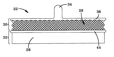
rubber exiting the gate system. FTG. 1 is a shaped portion of rubber 22 that
corresponds to
the internal flow passage through the inventive gate system 24. The inventive
gate system 24
is a combination of a lattice region 26 and a flat region 28. The entrance
section 30 of the
gate 24 is a lattice region 26 that provides a more uniform distribution of
rubber compound.
so The exit section 32 is a flat region 28 that orients fibers in the
injection direction. This unique
combination gate system 24 provides a uniformly distributed rubber flow to the
mold cavity 18
and, when using a fiber-loaded compound, improves the degree of fiber
orientation in a fiber-
loaded compound.
The improved gate system 24, illustrated in FTG. 2, incorporates a spree
channel 34, a
CA 02320555 2000-09-25
4
first distribution channel 36, a lattice region 26 of intersecting rubber flow
channels 38, 40, a
second distribution channel 44, and a flat region 28. The rubber 22 flows from
the spree
channel 34, into the first distribution channel 36, and into the intersecting
flow channels 38,
40. The intersecting rubber flow channels 38, 40 force the rubber 22 flowing
through the
lattice region 26 of the gate system 24. Because of this structure, rubber 22
exiting the lattice
region 26 is uniformly distributed when it enters channel 44. Upon entering
the flat region
28, because of the flow direction of the nibber 22 towards the gate exit 46,
any fibers present
in the rubber 22 are reoriented to be parallel to the rubber flow direction.
The components of the combination gate system 24 are more clearly illustrated
in
FIGS. 3-7. FIG 3 illustrates a plan view of the inner surface 48 of the gate
plate 50, which is
half of the combination gate 24 at the spree side. The plate 50 includes a
spree bore 52 that
extends from the outer surface 54 to the inner surface 48. The plurality of
flow channels 38
formed into the inner surface 48 of the plate 50 are parallel to each other
and inclined at
angles of about 30 ° to about 70 ° , preferably at angles of
about 45 ° to about 60 ° , with respect
is to a centerline 56. As the angle of the parallel flow channels 38 with
respect to the centerline
56 increases, the time required for the rubber 22 to transverse between the
inlet 58 and outlet
60 sides of the plate 50 also increases, and vice versa. The flow channels 38
are illustrated
with a semi-circular cross-section; however, it is within this invention to
form the flow
channels 38 with other cross-sections, such as elliptical, triangular, or
square as desired.
2o The flow channels 38 terminate in the distribution channel 61. Adjacent to
the
distribution channel 61 is an indented flat region 62, as seen in FIGS. 4 and
5. Rubber flows
directly from the channels 38 to the distribution channel 61 and into the flat
region 62 towards
the outlet end 60 of the spree plate 50. The depth of the distribution channel
and the depth of
the flat region may be equal or different as illustrated.
25 Referring now to Fig. 6, there is shown a plan view of the flat inner
surface 64 of the
other half of the combination gate plate 66 having an inlet end 68 and an
outlet end 70. A
spree inlet counterbore 72 extends into the inner surface 64 and is positioned
between the inlet
end 68 and the outlet end 70 of the plate 66. As illustrated in Fig. 7, the
spree inlet
counterbore 72 is in flow communication with an elongated distribution channel
74 extending
3o partially across the length of the plate 66 and in parallel relation to the
outlet end 70. A
plurality of flow channels 40 are formed in the inner surface 64 of the plate
66. The flow
channels 40 are formed similar to the channels 38 formed on the plate 50.
Adjacent to the flow channels 40 is a second elongated distribution channel 76
that
extends parallel to the first elongated distribution channel 74. An indented
flat region 78 is
CA 02320555 2000-09-25
formed extending from the second distribution channel to the outlet end 70 of
the plate 66.
Mixed rubber flows from the channels 40 to the second distribution channel 76
towards the
outlet end 70 of the plate 66. Also, as seen in FIG. 7, the distribution
channels 74, 76 have a
depth greater than the depth of the channels 40 or the indented flat portion
78.
s Referring to FIGS 2 and 2A, there is shown the inventive gate system 24 with
the flat
inner surface 48 of the sprue side gate plate 50 abutted against the flat
inner surface 64 of the
other side gate plate 66 and secured thereto by conventional means such as
bolting one to the
other. After the plates 50, 66 are secured to each other, the sprue bore 52
and the sprue inlet
counterbore 72 intersect to form sprue channel 34. Also, the inner surface 48
of plate 50
abuts against the elongated distribution channel 74 to form first distribution
channel 36.
Channels 38 and 40 abut against each other. Because the channels 38, 40 are
inclined in the
same direction in the plates 50, 66, when one plate is flipped over to abut
the two inner
surfaces 48, 64 of the plates 50, 66, the channels are then oriented in cross-
directions to form
the lattice region 26. The distribution channel 61 of the plate 50 abuts
against the distribution
~s channel 76 of plate 66 to form the second distribution channel 44. The
indented flat region 62
of the plate 50 abuts against the indented flat region 78 of the plate 66 to
form the flat region
28 with a constant thickness t.
An important aspect of the invention relates to the configuration of the flow
channels
38, 40 and the flat region 28 after the gate system 24 is assembled. The flow
channels 38, 40
2o are disposed to intersect each other at an angle of about 60 ° to
about 140 ° with respect to each
other, preferably about 90 ° to about 120 ° with respect to each
other. Also, portions of the
flow channels 38, 40 of plate 50 and plate 66, respectively, are partially
formed, typically
with a half circle or an elliptical shape, resulting from being abutted
against the flat inner
surface 48, 64 of the opposing plates 50 or 66. The remaining portions of the
flow channels
25 38, 40 are formed at the intersections 42 of the flow channels and are
illustrated in Fig 2A as
having an elliptical shape. The lattice portion 26 of the inventive gate
system 24 effectively
creates more physical mixing, rubber-to-rubber shear heating, and thermal
mixing than in the
flat design portion 28 of the gate system 24.
The flat region 28 provides for a preferred orientation of the fiber in the
rubber
3o compound 22. Due to the flow of the rubber 22 through the lattice channels
38, 40, the fibers
in the compound exiting the channels 38, 40 and entering the second
distribution channel 44
have an orientation corresponding to the channel inclination angle, relative
to the centerline 56
of the gate plates 50, 66. In order to achieve a rubber flow, and thus fiber
orientation,
parallel to the centerline 56 of the gate plates 50, 66, the flow direction of
the rubber must be
CA 02320555 2000-09-25
6
reoriented 60 ° to 20 ° , or 45 ° to 30 ° if the
channels 3 8, 40 are at the preferred inclination
angles. The necessary reorientation of the robber and fibers is less than any
required
reorientation of the fibers for known flat gate designs.
After the plates 50 and 66 are assembled, the flat region 28 has a thickness t
and a
s length 1F associated with it, see FIGS 2 and 2A. Both the thickness t and
the length 1F are
optimized to allow for the reorientation of the fibers carried within the
rubber 22 flowing
through the flat region 28 of the gate system 24. Because of the range of
fiber length, the
thickness t of the flat region 28 of the gate 24 must be comparably narrow
with respect to the
inlet ports known in the prior art in order that a majority of the fibers are
aligned with the
to flow direction F of the rubber 22 (see also FIG 8). Also, if the length lF
is teo long, the
rubber 22 may scorch or cure in the gate. If the length 1F is too short, then
the fibers may not
become fully oriented in the direction of flow F before entering the mold
cavity 18. Since the
fibers in the rubber 22 are entering the second distribution gate requiring a
reorientation of
only 70° to 30°, the length 1F can be reduced from that known
disclosed in WO 98/13185. As
is the rubber 22 flows the direction of flow F through the flat region 28 of
the gate 24, the fibers
become oriented parallel to the centerline 56 of the sprue and gate plates 50,
66.
After passing through the gate system 24 into the mold cavity 18, the flow
direction of
the rubber 22 is altered. As illustrated in FIG 8, at the gate exit 80,
located at the junction of
the gate system 24 with the mold cavity 18, the opening for the rubber 22 is
significantly
2o increased in the direction parallel to the thickness of the gate system 24.
'The rubber
compound 22 folds over onto itself, creating a series of planes 82 generally
perpendicular to
the initial direction F as the rubber 22 fills the mold cavity 18.
The offset distance d between the gate exit 80 and the interior walls 84, 86
of the mold
cavity 18 can also influence the orientation of the fibers. If the offset
distance d between the
2s gate exit 80 and the interior walls 84, 86 is too small, the rubber 22 may
get hung up or
temporarily attached to the nearest interior wall 84, 86. While some rubber
compounds 22
can be successfully run in some conditions where the offset distance d is
equal to zero,
generally the offset distance d should be greater than one-fourth of the mold
cavity width w.
However, in some particular applications, unless the offset distance d is
between one-fourth
3o and one-half the mold cavity width w, the type and number of folds
necessary to achieve the
desired fiber orientation may not occur. For more details regarding the
various parameters of
different applications, reference is made to the incorporated WO 98/13185.
Comparison Test
Comparisons between a flat gate and the inventive combination gate 24 were
prepared.
CA 02320555 2000-09-25
7
Samples of a Kevlar pulp loaded rubber compound were prepared using both a
flat gate and
the inventive combination gate 24. The combination gate 24 had a lattice
entrance structure
30 of 45/20/0.031"/0.51" (channel angle/number of channels/cha.nnel
radius/length) and a flat
gate exit structure 32 of 0.010"/0.5" (thickness/length). The flat gate had a
structure of
0.010"/1.0" (thickness/length). The barrel temperatures, mold temperatures,
and injection
speed for both samples. Both 5"x5"x7/8" block and 5"x5"x1/10" sheet samples
were
prepared.
Test Sample 1
Five samples were taken from sheet samples 1.0" from the gates. The five
samples
to were circular samples, spaced across the width of the sheet sample. The x
direction is the
lateral direction of the sheet, and y is the injection direction of the sheet;
the desired
orientation is y. The following chart shows the results of the orientation of
the fibers in the
samples, in comparison to the sample location. The solvent swell ratios given
in the table are
average of three samples and obtained by dividing the length in the y
direction by the length in
i5 the x direction. The swelling ratio is defined as a short axis divided by a
long axis when a
circular fiber loaded rubber sample is swelled into an oval shape in toluene
to equilibrium
state. The short axis direction is parallel to the fiber orientation
direction. Since fibers were
oriented in the short axis, the orientation direction is x if the swell ratio
is greater than 1.0 and
y if the swell ratio is less than 1Ø The smaller the swelling ratio, the
higher the degree of
2o fiber orientation.
Table 1
Sample LocationCombination Flat Gate
Gate
Average Std Dev DirectionAverage Std Dev Direction
left 0.880 0.024 y 0.918 0.063
Y
mid-left 0.854 0.021 y 1.057 0.052 x
center 0.901 0.017 y 1.280 0.096 x
mid-right 0.868 0.035 y 1.080 0.043 x
right 0.857 0.029 y 0.950 0.031 y
Overall 0.872 1.057
+/- +/- 0.142
0.019
It can be seen that samples made with the combination gate 24 had relatively
uniform
fiber orientation. The solvent swell ratios ranged from 0.86 to 0.90. On the
other hand,
25 samples made with the flat gate, with solvent swell ratios of 0.918 to
1.280, had relatively
CA 02320555 2000-09-25
8
strong orientation in the lateral direction (x) at the center. The orientation
gradually changed
to the injection direction (y) toward the sides of the sample, indicating non-
uniformity in the
fiber orientation. The standard deviations of solvent swell ratios are 0.019
and 0.142 for the
combination and flat gates, respectively. The results of the sheet samples
show that the
s combination gate 24 is much better in preparing injection molded parts with
uniform fiber
orientation and, thus, more uniform physical properties.
Test Sample 2
From block samples prepared by the combination gate 24 and a flat gate, a thin
slice
was cut at a location one inch from the gate and five samples were taken to
test the fiber
io orientation in the thickness direction (z) of the block. The five samples
were circular samples,
spaced across the width of the thin slice. Three block samples prepared under
identical
conditions were used to obtain variation in solvent swell data. As noted
above, the smaller the
swelling ratio, the higher the degree of fiber orientation.
is Table 2
Sample LocationCombination Flat Gate
Gate
Average Std Dev DirectionAverage Std Dev Direction
left 0.675 0.024 z 0.824 0.063 z
mid-left 0.679 0.021 z 0.725 0.052 z
center 0.688 0.017 z 0.779 0.096 z
mid-right 0.654 0.035 z 0.748 0.043 z
right 0.691 0.029 z 0.714 0.031 z
Overall 0.678 0.758
+/- 0.015 +/- 0.044
The results show that the block samples produced from the combination gate 24
had a
high degree of fiber orientation in the thickness direction. The average
solvent swell ratios are
0.678 and 0.758 for the combination and flat gates, respectively. The standard
deviation of
2o the solvent swell ratios for the combination gate is also lower, 0.015 vs.
0.044, indicating
more uniform fiber orientation within the sample.
The illustrated gate has a lattice region 26 and a flat region 28 that are of
substantially
the same length 1L, 1F. While this is the preferred length ratio of the
lattice region 26 and the
flat region 28, the ratio of the lattice region 26 to the flat region 28 may
vary from 2:1 to 1:2
25 and still achieve the desired high degree of fiber orientation in the
rubber exiting the gate
CA 02320555 2000-09-25
9
system 24.
The fibers in the rubber 22 injected into the combination gate system 24 may
be any
conventional fiber used in manufacturing fiber reinforced rubber articles.
This includes short
fibers have a length ranging from 0.1 microns to 103 microns and fibers have a
length up to
s and including 0.5 inch (1.2 cm). To properly orient fibers of the longer
lengths, the actual
length of the gate 24, the diameter of the flow channels 38, 40, and the
thickness t of the flat
region 28 may be increased to achieve the necessary mixing and reorientation
discussed above.
Additionally, while the disclosed invention illustrates a closed cavity mold,
it will be
appreciated by those skilled in the art that the mold may be an open ended
mold. In such a
io mold, the defined relationships between the gate exit 80 and mold walls 84,
86 remain as
described above; however, there is no end wall to limit the movement of the
uncured rubber
through the mold. Uncured rubber flow through the gate exit 80, forming the
folding planes
82, and continues through the cavity to form a continuous strip of rubber
defined by folded
planes 82 creating a rubber with oriented fibers.
is The inventive lattice/flat combination gate 24 offers both the advantages
of the lattice and
flat gates and an unexpected benefit of a higher degree of fiber orientation
in the thickness direction
and more uniform fiber orientation distribution. The achieved higher degree of
orientation can not
be achieved by using only the lattice gate or only the flat gate; nor would
such a greater degree of
orientation be eby the mem combination of the two gate designs.