Note: Descriptions are shown in the official language in which they were submitted.
CA 02320833 2000-08-18
WO 99/43115 PCT/US99/03103
R~NG/MESH OPTICAL NETWORK
This invention relates to the field of
optical data transport networks.
There are two predominant network
architectures for creating optical data transport
networks. These network architectures are commonly
referred to as "ring" and "mesh".
In a ring network architecture each node of
the network is connected to exactly two adjacent nodes
to form a ring topology. When a break occurs in the
ring, data traffic is looped back along a reverse
direction spare path to bypass the break in the ring.
Present day optical ring networks are implemented with
devices known as add/drop multiplexers (ADMs). An ADM
is an all optical switch that either chooses (or is
commanded to select) either a working path or spare
restoration path and switches traffic itself to these
paths.
The ADM ring architecture is attractive for
its simplicity and recovery speed, which is around 50
milliseconds. A drawback of the ADM ring architecture
is that it is impractical to implement large networks
as a single ring. Another drawback is that ADM ring
networks require that there be a 1:1 protect ratio
(i.e., one spare connection for each working
connection) in order to implement ring recovery.
In a mesh architecture nodes of a network can
be connected to more than two other nodes, and a given
signal may have many possible routes by which to
traverse the network. A network covering a large
CA 02320833 2000-08-18
WO 99/43115 PCTNS99/03103
geographical area is amenable to the mesh design. As
the network expands, nodes can simply be added at the
periphery and be connected to other nodes in any manner
as needed. In addition, nodes can be easily be added
S inside the network to provide more dense coverage of an
area as needed. With respect to network restoration,
the mesh architecture allows for sophisticated actions
to be taken in response to a failure. For example, if
a failure of several connections occurs suddenly within
the network, the switches within the network can
perform a coordinated switching operation to divert
traffic around the failure. For this purpose, most of
the spans within a mesh network are equipped with extra
connections (i.e., spare connections) that are used for
emergency backup when one or more working connections
fail.
Whereas an ADM ring architecture requires a
1:1 protect ratio, the mesh architecture allows a
considerably lower protect ratio due to the flexibility
of the mesh switching. The tradeoff is that mesh
restoration is more complex and more time consuming.
Mesh restoration requires on the order of 1 or 2
seconds to restor a span failure.
What is needed is a network design approach
that exhibits the simplicity and fast switching of an
ADM ring network yet offers the spare efficiency and
ease of growth characteristics of a mesh network.
The present invention provides a network
design that exhibits the simplicity and fast switching
of ADM ring networks yet offers the spare efficiency
and ease of growth characteristics of mesh networks.
The present invention accomplishes this by using
optical cross-connect switches, as opposed to ADMs, to
-2-
CA 02320833 2000-08-18
WO 99/43115 PCT/US99/03103
create self-healing optical ring networks. By creating
self-healing optical ring networks using optical cross-
connect switches the ring networks can be seamlessly
integrated with a mesh network of optical cross-connect
switches, thereby creating a ring/mesh network in which
an optical cross-connect switch can participate in both
the ring and mesh network. An optical cross-connect
switch participates in both the ring and mesh network
by provisioning a first set of ports within the optical
cross-connect switch to support ring traffic and by
provisioning a second set of ports within the optical
cross-connect switch to support mesh traffic.
A ring/mesh network according to the present
invention is a network of freely interconnected optical
cross-connect switches wherein one or more line-
switched ring configurations are created from at least
three of the optical cross-connect switches. Simply by
changing the switching logic of the optical cross-
connect switches within the ring/mesh network, new
optical rings can be created and existing optical rings
can be modified. This gives the network managers and
others a great deal of flexibility to make changes to
the network as traffic patterns change without
incurring hardware costs or significant network
downtime. The switching logic of optical cross-connect
switches can be expressed in switching tables or set of
logic equations. The switching logic may also be
expressed by a data structure of provisioning
parameters associated with each switch port. The
present invention, however, is not intended to be
limited to any particular switching logic.
Another advantage of the ring/mesh network
design is that it can provide a high spare efficiency.
-3-
CA 02320833 2000-08-18
WO 99/43115 PCT/US99/03103
For example, multiple rings can be created having a
common span. Spare capacity can then be shared among
these rings,~thereby lowering the spare to working
capacity ratio from 1:1 to 1:N. Furthermore, the spare
S capacity of the ring networks can also be shared with
the mesh network, thereby increasing spare efficiency.
That is, spare capacity within a ring network can be
used to carry mesh traffic in the event of a failure
within the mesh network. However, in one example, the
ring networks can have priority of use with respect to
ring spare capacity.
Still another advantage of implementing ring
networks using optical cross-connect switches is that
the ring networks can be of arbitrary depth and can
easily scale as traffic demands increase. For example,
using 18 port OCCSs, one can construct a 6 fiber ring,
or with a 24 port OCCSs, an 8 fiber ring network can be
built. The maximum number of fibers an optical ring
can be constructed with using OCCSs is only limited by
the port counts of the OCCSs. Conventional optical
ring systems constructed using ADMs, however, can
support only two/four fiber bi-directional rings or two
fiber unidirectional path switching.
Further features and advantages of the
2S present invention, as well as the structure and
operation of various embodiments of the present
invention, are described in detail below with reference
to the accompanying drawings.
The accompanying drawings, which are
incorporated herein and form part of the specification,
illustrate the present invention and, together with the
description, further serve to explain the principles of
-4-
CA 02320833 2000-08-18
WO 99/43115 PCT/US99/03103
the invention and to enable a person skilled in the
pertinent art to make and use the invention.
Fig. 1 is a network diagram illustrating a
mesh network consisting of optical cross-connect
switches and a ring network consisting of add-drop
multiplexers.
Fig. 2 is a network diagram illustrating a
network design according to one embodiment of the
present invention.
Fig. 3 illustrates in greater detail an
example configuration of optical cross-connect switches
in the ring network of Fig. 2.
Fig. 4 illustrates an example ring failure
scenario in the ring network of Fig. 2.
Fig. 5 illustrates an example configuration
of optical cross-connect switches in the ring network
of Fig. 2 in response to a failure occurring in a
working optical channel within the mesh network.
Fig. 6 illustrates an example failure
scenario where more than one failure has occurred
within a ring network.
Fig. 7 is a block diagram illustrating an
optical cross-connect switch controller.
Fig. 8 illustrates an example switching
table .
Fig. 9 is a diagram illustrating a four node
six fiber line-switched optical ring network according
to the present invention.
Fig. 10 illustrates an example failure
scenario for the ring network of Fig. 9.
The present invention is described with
reference to the accompanying drawings. In the
drawings, like reference numbers indicate identical or
-5-
CA 02320833 2000-08-18
WO 99/43115 PCTNS99/03103
functionally similar elements. Additionally, the left-
most digits) or a reference number identifies the
drawing in which the reference number first appears.
To more clearly delineate the present
invention, an effort is made throughout the
specification to adhere to the following term
definitions as consistently as possible.
The term "span", and equivalents thereof
refer to a path or route between any two nodes. A
span can extend between adjacent or non-adjacent nodes.
A span can extend between intermediate nodes, which
include optical switching elements, and/or endpoint
nodes, which include line terminal equipment (LTE).
The term "optical channel", "channel", and
equivalents thereof, refer to any type of optical
connection for transporting an optical signal between
two points.
The present invention provides a network
design that exhibits the simplicity and fast switching
of ring networks yet offers the spare efficiency and
ease of growth characteristics of mesh networks. The
present invention accomplishes this by implementing
ring networks using optical cross-connect switches as
opposed to using add-drop multiplexers. By
implementing ring networks with optical cross-connect
switches, the ring networks can be integrated with an
optical cross-connect mesh network. Optical cross-
connect switches that implement the ring networks can
form part of the mesh network.
The seamless integration of the ring and mesh
networks enable network engineers to configure ring
networks within a mesh optical cross-connect switch
network by provisioning optical cross-connect switches
CA 02320833 2000-08-18
WO 99/43115 PCTNS99/03103
to support mesh and ring topologies. To configure
additional ring networks, network engineers need only
modify the switching logic of the optical cross-
connects within the ring/mesh network and perhaps add
additional capacity to the network. The switching
logic of optical cross-connect switches can be
expressed in switching tables or set of logic
equations. The switching logic may also be expressed
by a data structure of provisioning parameters
associated with each switch port. For ease of
understanding the present invention, the invention will
be described in an environment where the switching
logic is expressed in switching tables. The present
invention, however, is not intended to be limited to
such an environment.
Fig. 1 illustrates the problem recognized by
the inventors in integrating mesh and ADM ring networks
where significant traffic demand exists among nodes B,
C, and D. Fig. 1 shows a network having an optical
mesh network 102 and a conventional ADM ring network
110. Due to the traffic demands among nodes B, C, and
D, ADMs 1, 2, and 3 are placed at those nodes to form'
ring network 110. Optical cross-connect switches can
be placed at nodes A-K, where the traffic is not as
critical, to form mesh network 102.
Whereas the network design of Fig. 1 suffices
for the situation where traffic is heaviest and most
important among locations B, C, and D, a problem arises
when some of the initial design parameters change. For
example, some time after the network has been deployed,
new traffic demands might make locations B, D, and E a
candidate for a ring network in addition to or in
replace of the initial ring network 110. In fact, at
CA 02320833 2000-08-18
WO 99/43115 PCT/US99/03103
any given point of time, as recognized by the
inventors, the network might best be implemented as
entirely mesh or as any combination of rings.
The problem with the design of Fig. 1 is that
conventional ADM ring network 110 is permanently
implemented as a ring structure using ADMs.
Consequently, if there were a subsequent desire to
alter the ring or convert it to be part of the mesh
network, hardware would have to be retrofitted
incurring considerable cost and network downtime. It
would be impractical to alter the network design on the
fly, as a function of the time of day, for example.
Another disadvantage of implementing ring and mesh
networks using different hardware is that it
complicates the sharing of spare capacity that exists
in each network.
Fig. 2 is a network diagram illustrating a
network design according to one embodiment of the
present invention. The network design of the present
invention overcomes the disadvantages of the network
design approach shown in Fig. 1 by implementing both
ring and mesh networks using optical cross-connect
switches (OCCSs). An OCCS is a switch that switches an
optical signal from one port to anther without optical-
to-electrical conversion and is bit-rate independent.
The switching of an OCCS is commonly controlled by an
OCCS controller (see Fig. 7). OCCS controllers detect
failures within a network by receiving failure
indications from line terminating equipment (LTEs) or
other fast, reliable fault detection system. Upon
receiving a failure indication, an OCCS controller will
consult a switching table to determine the switching
commands that it should send to its corresponding OCCS.
_g_
CA 02320833 2000-08-18
WO 99/43115 PCTNS99/03103
In this manner, an OCCS switches traffic to avoid
failures in the network.
Using the OCCSs to implement both mesh and
ring networks allows for the seamless integration of
'S ring network 202 and mesh network 102. By integrating
ring and mesh networks, as shown in Fig. 2, the present
invention offers numerous features and advantages to
overcome the disadvantages of the prior network
designs.
According to the present invention, ring
network 202 is formed using OCCSs B, C, and D of mesh
network 102. OCCSs B, C, and D participate in both
ring network 202 and mesh network 102 by provisioning a
first set of ports within each OCCS to support ring
IS traffic and by provisioning a second set of ports to
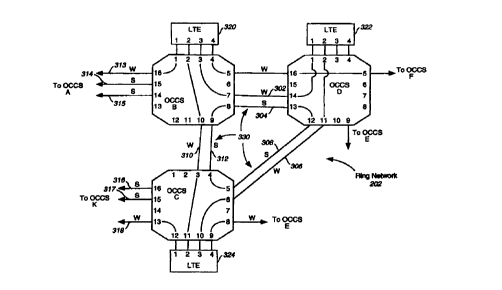
support mesh traffic. Fig. 3 illustrates in greater
detail the configuration of OCCSs B, C, and D. As
shown in Fig. 3, ports 2, 3, 7, 8, 9, 10 of OCCS B are
provisioned to support ring traffic. Ports 1, 4, 5,
and 16 are provisioned to support working mesh traffic.
Ports 14 and 15 are provisioned to support spare mesh
traffic. Mesh traffic can include traffic between
OCCSs or traffic between an LTE and an OCCS. Like OCCS
B, OCCS C and OCCS D both have a first set of ports to
support ring traffic and a second set of ports to
support working and/or spare mesh traffic.
In addition to provisioning the ports of OCCS
B, C, and D, ring network 202 is formed by providing at
least one working optical channel(w) and one spare
optical channels) between each OCCS that forms ring
network 202. Specifically, working optical channel 302
and spare optical channel 304 optically couple OCCS B
to OCCS D. Working optical channel 306 and spare
_9_
CA 02320833 2000-08-18
WO 99/43115 PCT/US99/03103
optical channel 308 optically couple OCCS D to OCCS C.
Lastly, working optical channel 310 and spare optical
channel 312 are optically coupled between OCCS C and
OCCS B.
OCCSs B, C, and D are switched such that port
2 of LTE 320 is optically coupled with port 2 of LTE
324 using working optical channel 310. Port 3 of LTE
320 is optically coupled with port 1 of LTE 322 using
working optical channel 302. Port 3 of LTE 324 is
optically coupled with port 2 of LTE 322 using working
optical channel 306.
OCCSs B, C, and D are also switched to form
spare optical channel ring 330, which is used for
carrying traffic in the event of a failure in one of
the working optical channels 302, 306, or 310. As
shown in Fig. 3, spare optical channel ring 330
includes spare optical channels 304, 308, and 312,
which are part of ring network 202. Spare optical
channel ring 330 is created by having OCCS B connect
spare optical channel 304 to spare optical channel 312,
OCCS D connect spare optical channel 304 to spare
optical channel 308, and OCCS C connect spare optical
channel 308 to spare optical channel 312. OCCS B
connects spare optical channel 304 to spare optical
channel 312 by switching port 8 to port 9. OCCS D
connects spare optical channel 304 to spare optical
channel 308 by switching port 13 to port 12. OCCS C
connects spare optical channel 308 to spare optical
channel 312 by switching port 5 to port 4.
Ring network 202 operates with fast, self-
healing behavior similar to that of ring network 110.
When a failure occurs in one of the working optical
channels 302, 306, 310 of ring network 202, data
-10-
CA 02320833 2000-08-18
WO 99/43115 PCT/US99/03103
traffic is looped back along a reverse direction spare
path to bypass the failed working optical channel. An
example failure scenario is shown in Fig. 4. Fig. 4
illustrates a break in the ring between OCCS B and OCCS
D. To bypass the ring failure, data traffic between
OCCS B and OCCS D is carried by spare path 402, which
includes spare optical channels 312 and 308. The data
traffic is placed on the spare path simply by having
OCCS B switch the optical signal received on port 3 to
port 9, instead of switching it to port 7, and by
having OCCS D switch the optical signal received on
port 12 to port 1, instead of switching it to port 13.
Because only this simple switching need take place to
recover from a ring failure, recovery occurs very
quickly.
If spare optical channel ring 330 was not
created, then it would have been necessary for OCCS C
to connect spare optical channel 312 to spare optical
channel 308 in response to the failure. But because
spare optical channel ring 330 was initially created;
OCCS C did not have to perform any actions for ring
recovery to occur. In short, spare optical channel
ring 330 facilitates ring recovery by reducing the
number of OCCS that have to respond to a span failure.
As discussed above, ring network 202
maintains the simplicity and fast switching of ring
networks implemented using ADMs. Furthermore, because
ring network 202 is integrated with mesh network 102,
the sharing of spare capacity between the networks is
facilitated. As an example, spare optical channels
304, 308, 312 of ring network 202 can easily be used as
backup paths by mesh network 102 in the event of a
failure in the mesh network. For example, assuming a
CA 02320833 2000-08-18
WO 99/43115 PCT/US99/03103
failure in mesh network 102 occurs in working optical
channel 313, which optically couples OCCS A to OCCS B,
the traffic from A to B can re-routed through OCCS K
and OCCS C (see FIG. 5). The recovery path from OCCS C
to OCCS B uses spare optical channel 312.
FIG. 5 illustrates the configuration for
OCCSs A, B, C and K in response to a failure occurring
in working optical channel 313 of mesh network 102. As
shown in FIG. 5, port 1 of LTE 320 is optically coupled
to port 2 of LTE 520 through OCCS B, C, K, and A and
spare optical channels 312, 317, and 504. In the
configuration shown in FIG. 5, spare optical channel
312, which is part of ring network 202, is utilized by
the mesh network. By sharing spare optical channels
between the ring and mesh networks, the network
realizes a significant increase in spare efficiency.
Ring network 202 can be given priority of use over
spare optical channel 312 so that mesh traffic will be
carried by spare optical channel 312 only when there
are no failures in ring network 202.
In addition to mesh network 102 being able to
utilize spare capacity in ring network 202, ring
network 202 can utilize spare capacity within mesh
network 102. Ring networks constructed using ADMs are
not able to recover from more than one failure within
the ring. However, the network..design of the present
invention enables ring networks to recover from more
than one failure by utilizing spare capacity within the
mesh network. This is a powerful feature not found in
conventional optical ADM ring networks.
Fig. 6 illustrates an example failure
scenario where more than one failure has occurred
within ring network 202. In the example of Fig. 6,
-12-
CA 02320833 2000-08-18
WO 99/43115 PCTNS99/03103
there is a failure between OCCS B and OCCS D and a
failure between OCCS B and OCCS C. To recover from
more than one failure in ring 202, ring traffic will be
switched onto spare capacity within mesh network 102.
As shown in Fig. 6, port 2 of LTE 320 is now optically
coupled with port 2 of LTE 324 through optical cross-
connect switches B, A, K, and C and spare optical
channels 314, 504, and 317. These spare optical
channels are space capacity within mesh network 102.
Similarly, port 3 of LTE 320 is optically coupled to
port 1 of LTE 322 through optical cross-connect
switches B, A, K, C, and D and spare optical channels
315, 506, 316, and 308. Spare optical channels 315,
506, and 316 are spare capacity of mesh network 102.
The network shown in Fig. 6 is but one example of how
ring network 202 can utilize spare capacity within mesh
network 102.
Additionally, in the interest of brevity,
Fig. 2 only shows one ring network 202 configured
within mesh network 102. The present invention is not
intended to be so limited. Any arbitrary number of
rings can be configured within mesh network 102
according to the present invention, as would be
apparent to a person skilled in the art given this
description. For example, using the same technique
described above to create a ring connecting nodes B, C,
and D, a ring connecting nodes E, G, H, and I or K, I,
H, and J, can also be created. Additionally, if two
rings are created wherein the rings share a common
span, such as rings B-C-D and A-B-C-K, then the
opportunity to share a spare optical channel between
the two rings is presented.
-13-
CA 02320833 2000-08-18
WO 99/43115 PCT/US99/03103
As noted above, the switching of an OCCS is
controlled by an OCCS controller. OCCS controllers
detect failures within a network by receiving failure
indications from line terminating equipment (LTEs) or
other fast, reliable fault detection systems. Upon
receiving a failure indication, an OCCS controller
consults a switching table to determine the switching
commands that it should send to its corresponding OCCS.
Fig. 7 is a diagram illustrating the OCCS controller
702 corresponding to OCCS B. OCCS controller 702
includes a system processor 704, control logic (e. g.,
computer software) 706 to be executed by system
processor 704, memory 708 for stor,'_ng switching table
710, OCCS interface 712 for coupling OCCS controller
702 to OCCS B, and data network interface 714 for
coupling OCCS controller 702 to a data network for
receiving network failure indications.
Switching table 710 determines the port
configuration of OCCS B. As shown in Fig. 8, switching
table 710 incudes three columns. An event column 802,
an action column 804, and a comments column 806. The
event column contains network events to which OCCS B
responds. For each network event listed in the event
column, there is a corresponding switching action that
OCCS B performs in response to the event. These
switching actions are stored in the switching column
804.
For example, one network event shown in event
column 802 is the network initiation event. The
switching action that OCCS B performs in response to
this event is to switch port 1 with port 16, port 2
with port 10, port 3 with port 7, port 4 with port 5,
and port 8 with port 9, as shown in action column 804.
-14-
CA 02320833 2000-08-18
WO 99/43115 PCT/US99/03103
The result of OCCS B performing these switching actions
can be seen by examining OCCS B as illustrated in Fig.
3. Another event shown in event column 802 is a B-D
span cut event. In response to this event, action
column 804 directs OCCS B to disconnect port 3 from
port 7, disconnect port 8 from port 9, and switch port
3 to port 9. Fig. 4 illustrates the configuration of
OCCS B in the event of a B-D space cut. Another event
shown in event column 802 is a A-B span cut event. If
spare optical channel 312 is not being used to restore
optical ring network 202, then in response to an A-B
span cut OCCS B disconnects port 8 from port 9,
disconnects port 1 from port 16, and switches port 1
with 9. In this manner ring network 202 is given
priority over the spare channels that comprise the
ring. Fig. 5 illustrates the configuration of OCCS B
in the event of an A-B span cut.
Each OCCS within mesh network 102 is
associated with a switching table equivalent to the one
shown in Fig. 8. Simply by changing the contents of
the switching tables, new rings within mesh network 102
can be formed without incurring a significant amount of
network downtime and without provisioning new hardware.
Another advantage to implementing rings using
optical cross-connect switches is that it enables one
to implement rings of arbitrary depth and to scale the
size of the rings as needed. Rings built using ADMs
are limited to four fibers. Consequently, when traffic
is increased such that a four fiber ring is
insufficient to handle the increase, a new ring must be
created. With the present invention, however, an N
fiber ring can be built by using optical cross-connect
switches having at last 3N ports. The ability to
-15-
CA 02320833 2000-08-18
WO 99/43115 PCT/US99/03103
configure an N fiber ring provides a great deal more
flexibility than an ADM ring network, which is limited
to four fibers. As traffic grows, the ring can simply
grow along with it, as opposed to having to build an
entire new ring to supplement the existing ring.
An example four node six fiber ring 900
according to the present invention is illustrated in
Fig. 9. As shown in Fig. 9, four OCCSs 902, 904, 906,
and 908 are configured to form ring network 900. Each
of the four OCCSs has at least 18 ports. OCCS 902 is
optically coupled to OCCS 904 by three working optical
channels 920 and by three spare optical channels 922.
In a like manner, OCCS 902 is optically coupled to OCCS
908 by working optical channels 932 and spare optical
channels 934. OCCS 904 is optically coupled to OCCS
906 by working optical channels 924 and spare optical
channels 926. OCCS 906 is optically coupled to OCCS
908 by working optical channels 928 and spare optical
channels 930. Ring network 900 is switched to form
three spare optical channel rings 960 using spare
optical channels 922, 926, 930 and 934.
Ring network 900 operates equivalently to
ring network 202. When a failure occurs in ring
network 900, working traffic is switched onto a spare
path in the opposite direction to avoid the failure
(see Fig. 10). Fig. 10 illustrates an example failure
scenario for ring network 900. Data traffic between
ports 4, 5, 6, and LTE 940 and ports 1, 2, 3 of LTE 942
is normally carried over working optical channels 920
(see Fig. 7). When a failure occurs in working optical
channels 920, this failure will be detected by an OCCS
controller and/or network management system, for
example, and a switch command will be transmitted to
-16-
CA 02320833 2000-08-18
WO 99/43115 PCT/US99/03103
OCCS 902 and OCCS 904. The switch command sent to OCCS
902 will cause OCCS 902 to disconnect ports 4, 5, 6 of
LTE 940 from working optical channels 920 and to
optically couple those ports to spare optical channels
934 by optically coupling port 4 to port 15, port 5 to
port 14 and port 6 to port 13 of OCCS 902, as shown in
Fig. 10. Similarly, the switch command sent to OCCS
904 will cause OCCS 904 to disconnect ports 1, 2, and 3
of LTE 942 from working optical channels 920 and to
optically couple those ports to spare optical channels
926 by optically coupling port 1 to port 18, port 2 to
port 17, and port 3 to port 16 of OCCS 904. Spare
optical channels 926 are optically coupled to spare
optical channels 934 through spare optical channels 930
and OCCSs 906 and 908. Thus, spare optical channels
926, 930, and 934 provide an alternate data traffic
path that allows optical data signals to be transmitted
between ports 4, 5, and 6 of LTE 940 and ports 1, 2,
and 3 of LTE 942, thereby restoring the network when a
failure occurs in working optical channels 920.
As would be apparent to a person skilled in
the art given the above description of a six fiber
optical ring, the present invention can be used to
create an N fiber optical ring, where N is a positive
~ integer. An N fiber ring can be built by using optical
cross-connect switches having at least 3 N ports. As
stated above, the ability to configure an N fiber ring
provides a great deal more flexibility than an ADM ring
network, which is limited to four fibers.
While various embodiments of the present
invention have been described above, it should be
understood that they have been presented by way of
example, and not limitation. It will be understood by
-17-
CA 02320833 2000-08-18
WO 99/43115 PCT/US99/03103
those skilled in the relevant art that various changes
in form and detail may be made therein without
departing from the spirit and scope of the invention as
defined by the following claims. Thus, the breadth and
scope of the present invention should not be limited by
any of the above-described exemplary embodiments, but
should be defined only in accordance with the following
claims and their equivalents.
-I 8-