Note: Descriptions are shown in the official language in which they were submitted.
CA 02320904 2004-06-25
Improved Tooth Form For A Saw Blade.
Field Of The Invention
The present invention relates generally to saw blades, and deals more
particularly with an improved tooth form for providing enhanced discharge of
chips from the
gullet area of each tooth and improved tooth strength.
Background Of The Invention .
1 S The terms used herein to describe the profile of a saw blade tooth are to
be
construed in accordance with the definitions found in International Standard
Number ISO
4875/1-1978. In addition, the phrase "effective gullet radius" as used herein
should be
construed to mean the horizontal distance from the leftmost point of the
gullet area, when the
saw blade is viewed with the teeth pointing upward, to the point where the
gullet depth
reaches its maximum value.
In many instances, particularly in production settings, it is desirable to cut
materials such as wood, plastic, and metal at the highest feed rates
achievable. However, the
rate at which a particular material can be presented to the saw blade is
governed in large part
by the stresses induced in the teeth of the blade, as well as by the rate at
which particles or
chips generated by the cutting action of the blade are discharged from the
gullet area between
consecutively spaced teeth.
In prior art tooth forms, the effective gullet radius is relatively small,
typically
less than approximately 25% of the tooth pitch. In addition, the gullet depth
or gullet depth is
typically between about 40% and about 50% of the tooth pitch with the length
of the rake
CA 02320904 2000-07-28
WO 99/38661 PCTNS99/02113
- 2-
face accounting for approximately half of the height. As a result of this
relatively small
effective gullet radius and the relatively long rake face, shear stresses are
concentrated at the
base of each tooth on the saw blade which often are of sufficient magnitude to
tear or shear a
tooth from the saw blade during a cutting operation.
Another problem associated with known tooth forms having a profile similar
to that described above is that during a cutting operation, the long rake face
combined with a
small gullet radius inhibits the flow of chips out of the gullet area by
acting as a barrier. This
creates the potential for the chips generated during a cutting operation to
become lodged in
the gullet area, which in turn diminishes the cutting efficiency of the saw
blade. To minimize
this problem, the feed rate of the material through the saw, or the cutting
speed of the blade,
must be reduced, resulting in a concomitant reduction in production.
Based on the foregoing, it is the general object of the present invention to
provide a saw blade employing a tooth prof le that overcomes the above-
described drawbacks
of prior art saw blade teeth.
It is a more specific object of the present invention to provide a saw tooth
profile having enhanced chip discharge characteristics.
Summar~r Of The Invention
The present invention is directed to a saw blade having a cutting edge defined
by a plurality of teeth disposed along the blade. Each of the teeth includes a
tip, a rake face, a
relief surface, and a curvilinear base surface, with the tip of one tooth and
the tip of the next
consecutive tooth defining a pitch distance therebetween. The tip of each
tooth and the
curvilinear base surface disposed between consecutively spaced teeth cooperate
to define a
maximum gullet depth. In addition, the rake face of each tooth and the
curvilinear base
surface cooperate to define the effective gullet radius.
To provide enhanced chip discharge capabilities over prior art saw blades, the
saw tooth profile of the present invention includes an effective gullet radius
that is greater
than approximately 25% of the pitch distance, and 55°/a of the maximum
gullet depth. This
larger radius extends upwardly toward the tip of the tooth leaving only a
small vertical rake
face, thereby minimizing any barriers that would inhibit the flow of chips
from between the
teeth of the blade. To further improve the chip discharge characteristics, the
tooth profile can
also be formed such that the relationship between the pitch distance and the
height of the
tooth is optimized. Preferably, the gullet depth of the saw blade of the
present invention is
greater than approximately 40% of the pitch distance.
CA 02320904 2000-07-28
WO 99/38661 PCT/US99/02113
- 3-
In addition to the foregoing, each saw tooth may include a primary relief
surface defined by a first relief angle extending from the tip of the tooth in
a direction
opposite to the cutting direction of the saw blade, and a secondary relief
surface extending
from the first relief surface and defined by a second relief angle different
from, and larger
than, the first relief angle. Preferably, the first relief angle is
approximately 35° and the
second relief angle is between about 45° and about 55°, with
both the first and second relief
angles being measured from a plane approximately perpendicular to the cutting
direction of
the blade. The presence of the secondary relief surface, coupled with the fact
that the second
relief angle is larger than the first relief angle, increases the gullet area
between consecutive
teeth over that which would be achieved if only the first relief angle were
present. This
increased gullet area reduces the likelihood of chips lodging between
consecutively disposed
teeth by providing a larger gullet area for chips to collect. The increased
gullet area also
allows the rate of chip ingress to, and egress from, the gullet area to
equilibrate during a
cutting operation.
1 S In addition to providing enhanced chip discharge capabilities over that of
known saw blades, it is also desirable to maximize the stress-bearing
capabilities of the saw
teeth. Accordingly, the teeth of the saw blade of the present invention employ
a relatively
short rake face, preferably less than 25% of the gullet depth, and a large
radius tangent to the
rake face which is defined by the curvilinear base surface. The combination of
the short rake
face and large radius increases the stress-bearing characteristics of the saw
teeth by providing
greater tooth width at the base of each tooth where stresses are greatest,
without increasing
the gullet depth. This reduces the likelihood of the teeth shearing or tearing
during a cutting
operation.
Brief Description Of The Drawings
FIG. 1 is an enlarged partial side elevational view of the saw blade of the
present invention;
FIG. 2 is an enlarged partial side elevational view of an alternate embodiment
of the saw blade of FIG. 1;
FIG. 3 is an enlarged partial side elevational view of an alternate embodiment
of the saw blade of FIG. 1; and
FIG. 4 is an enlarged partial side elevational view of an alternate embodiment
of the saw blade of FIG. 1.
Detailed Description Of The Preferred Embodiments
CA 02320904 2000-07-28
WO 99/38661 PCT/US99/OZ113
- 4-
Detailed Description Of The Preferred Embodiments
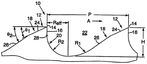
FIG. 1 illustrates a saw blade embodying the invention. The saw blade,
generally designated by the reference numeral 10, includes a cutting edge
defined by a
plurality of saw teeth 12, each tooth having a tip 14, a rake face 16, and a
relief surface 18
extending from the tip in a direction opposite to the saw blade's cutting
direction designated
in FIG. 1 by arrow A. The teeth 12 are spaced along the cutting edge with the
tip of one tooth
and the tip of the next consecutively disposed tooth cooperating to define a
pitch distance P.
A curvilinear base surface 20 extends between the rake face I6 of one tooth 12
and the relief
surface 18 of the next consecutive tooth. As shown in FIG. 1, the base surface
20 is tangent
to the rake face 16. The rake face 16, the curvilinear base surface 20, and
the relief surface 18
cooperate to define a gullet area 22. In addition, an effective gullet radius
R,~e. is defined by
the rake face 16 and the curvilinear base surface 20. Rya. is equal to the
horizontal distance
from the leftmost point of the gullet area 22, when the saw blade 10 is viewed
in the
orientation shown in FIG. 1, to the point where the gullet depth or gullet
depth H reaches its
maximum value.
Still referring to FIG. 1, the relief surface 18 includes a primary relief
surface
24 extending from the tip 14 of the tooth 12 and a secondary relief surface 26
extending from
the primary relief surface tangent to a radius R1 defined by the curvilinear
base surface 20.
The primary and secondary relief surfaces, 24 and 26, respectively, are
further defined by f rst
and second relief angles, Bl and 92, respectively, measured from a plane
extending parallel to
the cutting direction A of the saw blade 10. Preferably, the second relief
angle B2 is larger
that the first relief angle 9,, thereby increasing the size of the gullet area
22 over that which
would be possible if only the first relief surface were present.
In the embodiment of the present invention illustrated in FIG. 1, the
effective
gullet radius Reff is greater than approximately 25%, and preferably equal to
about 30% of the
pitch distance P. In addition, the effective gullet radius RED. is greater
than approximately
55% of the gullet depth H, and is preferably between about 65% and 85% of the
gullet depth,
and most preferably equal to about 81 % of the gullet depth. Moreover, the
length of the rake
face 16 between the tip I4 of the tooth 12 and the point where the rake face
is tangent to a
radius R2 defined by the curvilinear base surface 20, is preferably less than
25% of the gullet
depth. This relatively short rake face length allows the radius R2 to be
maximized, thereby
minimizing stress at the base of the tooth.
Still referring to FIG. I, during a cutting operation, chips generated by the
saw
blade 10 flow into the gullet areas 22 between consecutively disposed teeth
12. As the
cutting operation continues, the chips must be discharged from the gullet
areas 22 so that
CA 02320904 2000-07-28
WO 99/38661 PCT/US99/02113
- 5-
newly generated chips can be accommodated. The large effective gullet radius
R,~~, the
relatively short rake face 16, the primary and secondary relief surfaces, 24
and 26,
respectively, and the curvilinear base surface 20 all cooperate to define a
gullet area 22 that
provides for the smooth ingress and egress of chips to and from the gullet
area.
A second embodiment of the saw blade of the present invention, shown in
FIG. 2, is generally designated by the reference numeral 110. The saw blade
110 is similar in
many respects to the saw blade 10 described above, and therefore like
reference numerals
preceded by the number 1 are used to indicate like elements. The saw blade 110
differs from
the saw blade 10 in that the effective gullet radius R.~ff is approximately
36% of the pitch
distance P and approximately 77% of the gullet depth H. In addition, the
gullet depth is
approximately 46% of the pitch distance P.
Still referring to FIG. 2, the relief surface 118 includes a primary relief
surface
124 extending from the tip 114 of the tooth 112, and a secondary relief
surface 126 extending
from the primary relief surface tangent to the radius R,oi defined by the
curvilinear base
surface 120. The primary and secondary relief surfaces, 124 and 126, are
fiuther defined by
first and second relief angles, 9io~ and 9~oz, respectively, measured from a
plane extending
parallel to the cutting direction of the saw blade 110. Preferably, the second
relief angle 902
is larger than the first relief angle B~o~. In the illustrated embodiment B~oi
is approximately
35°, and 602 is approximately 45°.
A third embodiment of the saw blade of the present invention is shown in FIG.
3 and is generally designated by the reference number 210. The saw blade 210
is similar in
many respects to the saw blade 10 described above, and therefore like
reference numerals
preceded by the number 2 are used to indicate like elements. The saw blade 210
differs from
the saw blade 10 in that the effective gullet radius Ruff is approximately 41
% of the pitch
distance P and approximately 79% of the gullet depth H. In addition, the
gullet depth is
approximately 46% of the pitch distance.
The relief surface 218 includes a primary relief surface 224 extending from
the
tip 214 of the tooth 212, and a secondary relief surface 226 extending from
the primary relief
surface tangent to the radius R2o~ defined by the curvilinear base surface
220. The primary
and secondary relief surfaces, 224 and 226, are further defined by first and
second relief
angles, 820 and 6202, respectively, measured from a plane extending parallel
to the cutting
direction of the saw blade 210. Preferably, the second relief angle 8102 is
larger than the first
relief angle Bzo~. In the illustrated embodiment B2oi is approximately
35°, and B2o2 is
approximately 55°.
CA 02320904 2000-07-28
WO 99/38661 PCTNS99/02113
A fourth embodiment of the saw blade of the present invention is shown in
FIG. 4 and is generally designated by the reference numeral 310. The saw blade
310 is
similar in many respects to the saw blade 10 described above, and therefore
like reference
numerals preceded by the number 3 are used to indicate like elements. The saw
blade 310
differs from the saw blade 10 in that the rake face 316 defines a positive
rake angle Bra
measured from a plane extending approximately perpendicular to the cutting
direction A of
the saw blade 310. While the angle ~~o is positive in the illustrated
embodiment, the present
invention is not limited in this regard as 6r,~~ can also be zero or negative
without departing
from the broader aspects of the invention.
IO The embodiment illustrated in FIG. 4 also differs from the other
embodiments
described above in that the curvilinear base surface 320 is defined by a
combination of radii,
R3oi and R3o2, with rectilinear portion L3o, interposed therebetween. In
addition, the relief
surface 318 includes a primary relief surface 324 defined by relief angle
B3o~, and a secondary
relief surface 326 def ned by radius R3o3. In the illustrated embodiment, the
radius R3o3 1S
tangent to the primary relief surface 324 and the radius R3o1 defined by the
curvilinear base
surface 320. In addition, the radius R3o3 is convex relative to the radius
R3o~ defined by the
curvilinear base surface 320. However, the invention is not limited in this
regard as the
radius R3o3 can be either convex or concave and does not have to be tangent to
the primary
relief surface 324 or the curvilinear base surface 320. In addition, while the
curvilinear base
surface 320 has been shown and described as being defined by a combination of
radii, R3o~
and R3o2, with rectilinear portion L3oi interposed therebetween, the present
invention is not
limited in this regard. The curvilinear base surface 320 can be defined by any
combination of
radii and rectilinear sections without departing from the broader aspects of
the present
invention. Moreover, the relief surface 318, while shown and described in the
illustrated
embodiment as including a rectilinear primary relief surface 324 and a radial
secondary relief
surface 326, is not limited in this regard as any combination of radial and
rectilinear surfaces
can be employed without departing from the broader aspects of the present
invention.
Refernng to FIGS. 2-4, during a cutting operation, chips are generated by the
saw blades, 110, 210, or 310, which flow into the respective gullet areas. As
the cutting
operation continues, the chips must be discharged from the gullet areas so
that newly
generated chips can be accommodated. The larger effective gullet radii Reff,
the relatively
short rake faces, the larger angles or radii of the secondary relief surfaces
126, 226, and 326,
as well as the curvilinear base surfaces 120, 220, or 320 of each of these
blades, all cooperate
to define gullet areas larger than those of known saw blades. The larger
gullet areas provide
the saw blades with the capability to handle larger volumes of chips, thereby
enabling the
CA 02320904 2000-07-28
WO 99/38661 PCT/US99/02113
_ '7_
blades to operate at higher speeds. In addition, the large radii which def ne
the curvilinear
base surfaces provide the teeth of these blades with enhanced stress-bearing
capabilities by
minimizing any stress concentrations at the base of the teeth. This in turn
reduces the
likelihood of the teeth shearing or tearing from the blades, thereby enabling
them to cut
materials at higher speeds which would normally impose large amounts of stress
on the teeth.
While preferred embodiments have been shown and described, various
modifications and substitutions may be made without departing from the spirit
and scope of
the present invention. Accordingly, it is to be understood that the present
invention has been
described by way of example, and not by limitation.
is