Note: Descriptions are shown in the official language in which they were submitted.
CA 02321457 2000-08-17
WO 99/42710 PCT/US99/03637
-1- -
METHOD FOR PROVIDING AND MAINTAINING CATALYTICALLY
ACTIVE SURFACE IN INTERNAL COMBUSTION ENGINE
TECHNICAL FIELD
The invention generally relates to internal combustion engines. More
specifically,
the invention relates to fuels, lubricants and additives. Another aspect of
the invention
generaIly relates to combustion and more specifically to processes of
combustion operation,
especially to feeding a flame modifying additive. Specifically disclosed is a
method for
providing and maintaining a catalytically active surface on combustion-exposed
parts of
an internal combustion engine, such as fire deck, valve faces and piston
faces, so that
combustion efficiency is improved and harmful exhaust emissions are reduced.
The
invention is particularly applicable to improving combustion in "green"
engines, such as
engines that are new, recently rebuilt, or that have low operating hours.
BACKGROUND ART
Worldwide emphasis on reducing global warming and reducing pollution mandates
improved efficiency in combustion processes, which can be defmed as improved
fuel
efficiency coupled with reduced emission of pollutants such as oxides of
nitrogen (NOx).
Ferrocene is known to improve combustion efficiency in burners, for example
from U.S.
Patent No. 3,341,311. In quantitative terms, it has been reported that
ferrocene can
produce a 10% improvement in fuel efficiency. However, such results have not
been
uniformly achieved, especially with modem design, low emission engines, both
new and
after they have been in service for an extended time. Such modem engines,
i.e., newer
than 1995, are designed and constracted to consume less lube oil. In addition,
they use
cleaner fuels, lower in aromatic and sulfur content. All of these factors
combine to
minimize combustion chamber deposits. While modern engines running on modem
fuels
emit fewer pollutants than older engines, the technology has compromised the
effective use
of ferrocene to achieve still greater improvements.
In older literature, ferrocene was tested in diesel engines and showed
effectiveness
CA 02321457 2000-08-17
WO 99/42710 PCT/US99/03637
-2-
as
a fuel additive for conditioning the engines to achieve improved fuel economy
and
reduced emissions. United States Patent No. 4,389,220 to Kracklauer discloses
a two-stage
method of conditioning a diesel engine, resulting in reduced pollutant
emissions and
increased efficiency in fuel combustion. According to this patient, an initial
high dosage
of ferrocene, such as 20-30 ppm, in the diesel fuel can eliminate carbon
deposits from the
combustion chambers and deposit a layer of catalytic iron oxide on the
combustion
surfaces. Thereafter, a lower dosage of ferrocene, such as 10-15 ppm,
maintains the
catalytic iron oxide coating. It is considered undesirable to maintain the
initial high
concentration of ferrocene in diesel fuel, as this will lead to detrimental
combustion
modifications, minimizing or eliminating the beneficial effects of the
catalytic iron oxide
wall coating.
Older literature also shows that ferrocene can be effective in gasoline
engines by
improving the octane rating of treated fuel. In this way, ferrocene can reduce
certain
exhaust emissions and decrease fuel consumption in gasoline powered vehicles.
Schug,
K.P., Guttann, H.J., Preuss, A.W., and Schadlich, K., Effects of Ferrocene as
a Gasoline
Additive on Exhaust Emissions and Fuel Consumntion of Catalyst Eaui:pned
Vehicles, SAE
Technical Paper Series, 1990, paper number 900154. The method disclosed in
this article
and in related U.S. Patent No. 4,955,331 is the simple addition of ferrocene
to fuel as a
method of achieving improvements in efficiency and emissions. This technology
recently
was tested with a modern engine using modern fuels. The test vehicle was a
1998 Dodge
Intrepid with 29,500 miles on the odometer before testing started. Three fuel
fills without
ferrocene, corresponding to over 882 miles of operation, yielded a 27.7 mpg
average fuel
efficiency. Subsequently, four fills with ferroc,ene tteatment, cormsponding
to 1170 miles,
yielded a 26.4 mpg efficiency. These results suggest that simple addition of
ferrocene to
fuel as taught by Schug et al is not an effective method of improving
combustion in such
a gasoline fumled modern engine.
Other tests show that ferrocene does not produce combustion improvement in
every
case, especially when an engine is of modern design. A recent test with a 1998
Detroit
Diesel Series 60 engine followed the process of U.S. Patent 4,389,220 after
the engine had
accumulated 350 hours of break-in operation. Specifically, the engine was
operated for
5 hours at a 125 ppmw dose of ferrocene to the fuel, followed by switching to
a 25 ppmw
CA 02321457 2000-08-17
WO 99/42710 PCT/USM03637
-3-
for emissions testing. The test results showed no change in the fuel
efficiency or
dose
NOx emissions of the engine. Hence, the simple staged addition of ferrocene to
fuel as
disclosed in U.S. Patent 4,389,220 was not effective to improve performance of
this
modern design diesel engine.
Another approach to improved combustion is by the catalytic coating of
combustion
chambers prior to assembly and operation of the engine. In work described in
Gaffney et
al. "Soot Reduction in Diesel Engines: A Chemical Approach," a diesel
combustion
chamber coated with platinum demonstrated a 40% particulate emission
reduction.
Unfortunately, this combustion catatytic effect was fully lost after 50 hours
of normal
engine operation.
Siegia and Plee, "Heterogeneous Catalysis in the Diesel Combustion Chamber,"
attempted to duplicate Gaffney's result with a new engine having a platinum
coating.
However, no catalytic activity of any kind was found, despite use of the same
platinum
coating. This series of experiments showed two of four unre.solved problems
with
platinum coatings: 1) the catalytic effects are non durable; and 2) the
catalytic effects are
not reproducible. The remaining two unresolved problems with platinum are high
cost and
the toxicity of platinum as an exhaust pollutant, itself.
Other ferrocene related technology is disclosed in U.S. Patent 4,612,880 to
Brass
et al., which discloses a method of controlling octane requirement increase in
internal
combustion engines. This method requires introduction of a gasoline soluble
iron
compound such as dicyclopentadienyl iron (ferrocene) together with a
carboxylic acid or
ester derivative thereof, into a combustion chamber coated with atumina or
zirconia with
acubon gassification catalyst dispersed therein. However, this technology
involving base
metal surface catalysis is not effective for the process of this invention, as
shown in the
test reported at Table 1, 5b2 of this document. In addition, the disclosed
catalyst
compositions are prepared from soap or salt precursors and used in thick
coatings, which
deteriorate combustion efficiency.
SAE Paper 910461 discloses a thermal barrier coating that produces increased
combustion efficiency of 1.7%. An undesirable effect of this thermal burner
coating is an
increase in NOx output, which is unacceptable in modern engines facing severe
emission
control constraints.
CA 02321457 2000-08-17
WO 99/42710 PCT/US99/03637
-4-
would be desirable to provide improved combustion efficiency by a method or
It
coating that can be made effective even when an engine is "green," or has few
operating
hours, such that the combustion surfaces have not yet developed substantial
combustion
deposits.
Similarly, it would be desirable to provide the previously known benefits of
ferrocene usage in engines of modern design, i.e., post 1995, having low
consumption of
lube oil and adapted to use modern fuels with lower aramatic and sulfur
contents.
Further, it would be desirable to develop a durable or maintainable coating
for the
combustion chamber that can maintain the combustion facing surfaces at
catalyticaily
active temperatures, despite the attachment of the durable insulating coating
on the
combustion facing surfaces to a coolant-cooled wall surface.
In combination with providing a catalydcally active combustion chamber surface
for improved combustion efficiency, it would be desirable to provide a device
or system
to continuously maintain the active nature of the surface.
To achieve the foregoing and other objects and in accordance with the purpose
of
the present invention, as embodied and broadly described herein, the method of
this
invention may comprise the following.
DISCLOSURE OF INVENTION
Against the described background, it is therefore a general object of the
invention
to provide an improved, reliable and durable, catalyticaUy active film on the
combustion
facing surfaces of a combustion chamber, such as the fire deck, valve faces
and piston
faces, in order to improve combustion, even when an engine is "green," has few
prior
operating hours, is of a design allowing reduced consumption of lube oil, or
uses cleaner
fuels of lower aromatic and snlfur content.
A related object is to provide a method of forming or depositing an improved,
catalytically active film on the combustion facing surfaces of a combustion
chamber, such
as the fire deck, valve faces and piston faces, in order to improve
combustion.
Another object is to provide a catalytically active surface and method of
forming
such surface in a combustion chamber that is capable of maintai.ning a
temperature in the
catatydcally active range despite the connection of the combustion facing
surfaces to a
coolant cooled wall surface, which may be at temperatures below 320 C..
CA 02321457 2000-08-17
WO 99/42710 PCT/US99/03637
-5-
Still another object is to provide a method to incorporate into or on to a
combustion
facing surface of a thermally insulating coating a catalytically active metal,
which is active
in carbon particulate and fuel oxidation at catalytically active surface
temperatures.
An important object is to provide an effective method and system for
delivering a
maintenance dosage of a catalyst precursor in the combustion charge to each
cylinder so
that the catalytic activity of an existing catalyst is continuously maintained
and refreshed.
Additionai objects, advantages and novel featums of the invention shatl be set
forth
in part in the description that follows, and in part will become apparent to
those skilled in
the art upon examination of the following or may be learned by the practice of
the
invention. The object and the advantages of the invention may be reaaized and
aitained
by means of the instnunentalities and in combinations particularly pointed out
in the
appended claims.
According to the method of this invention, improved combustion is achieved in
an
internal combustion engine of the type igniting a combustion charge in an area
having a
combustion facing engine surface. The method provides the initiat step of
applying to a
combustion facing engine surface a substrate layer of high thermal inertia.
This initial step
is performed in either of two ways: a substrate precursor may be supplied in
the
combustion charge during engine operation; or a thermal barrier coating may be
supplied
on the combustion facing engine surface prior to engine assembly.
Simultaneously or
subsequently to the initial step, a fju-ther step of the method provides a
catalyst surface on
the substrate layer. This catalyst surface is of the type active in carbon
particulate and
hydrocarbon oxidation at a surface temperature of at least 450 C. In a next
step of the
method, during operation of the internal combustion engine and subsequent to
the step of
providing the catalyst surface, a maintenance dosage of a catalyst precursor
is provided in
the combustion charge to the catalyst surface on a substantially continuous
basis during
stable engine operation. Thus, catalytic activity is substantially
continuously maintained.
In the method, the internai combustion engine may be either a compression
ignition
engine or a spark ignition engine. The substrate layer is of a material having
a surface
area of 300 to 500 meters per gram as measured by BET nitrogen absorption. It
may be
of 100 to 100,000 angstroms thickness and is prefened to be a film of less
than 0.1 mm
thickness. The preferred substrate layer is selected from zirconia, silica,
and lube oil ash.
CA 02321457 2007-02-13
-6-
According to the method, the substrate may be formed of a thermal insulating
compound effective in providing a high theimal inertia to the catalytic
surface to maintain it in
a catalytically active temperature region during stable engine operation. The
thermal
insulating compound may be of the type effective to maintain the catalyst
surface at a
temperature of at least 450 C during stable engine operation.
The method pi-ovides that the catalyst surface may be selected fi-om nanophase
iron,
nanophase platinum, and combinations of the two. The catalyst surface may be
created during
operation of the engine by supplying a combustion charge containing feirocene
in an effective
dosage to establish a catalytic iron coating. This combustion charge may
contain fen-ocene in
a dosage range fi-om 25 to 120 ppmw of engine fuel. The step of providing the
catalyst surface
may be pei-formed simultaneously with the step of providing the substrate
layer. The catalyst
pi-ecursor preferably is supplied in a dosage fi=om 5 to 50 ppmw of engine
fuel. The catalyst
pl-ecursor may be fer-rocene. The fer-rocene may be provided to the combustion
chamber by
adding it to the fuel or to lube oil, or by vaporization into the intake air
to the engine.
In another aspect, the present invention provides a method of catalytically
improving
the efficiency of fuel combustion in an internal combustion engine of low lube
oil
consumption design such that the engine has not developed sufficient
combustion deposits on
a combustion chambei- surface to maintain a combustion catalyst nanophase
surface thereon
at a surfaee temperature effective for substantially impi-oving efficiency of
fuel combustion,
comprising: fiist, providing on a combustion facing engine sui-face a
combustion-durable
substrate layer of high thermal inei-tia and having a surface area of 300 to
500 square metel-s
per gram as measured by BET nitrogen absolption, by a step selected from the
group
consisting of: supplying a substrate precursor in the combustion charge during
engine
operation by dissolving the substrate precuisor in the fuel supply and feeding
the substrate
precursor into the combustion chamber with the fuel charge for deposition
during the
combustion of the fuel and discontinuing the supply of substrate precursor in
the fuel supply
after deposition of a substrate coating effective to support a nanophase
catalyst surface,
supplying a thermal bai-rier coating on the combustion facing engine sui-face
pl-ior to engine
assembly, and combinations thereof, simultaneously with or subsequently to
said first step,
providing in association with said substrate layei- a nanophase catalyst
surface of the type
active in carbon particulate and fuel oxidation at a surface tempei-ature of
at least 450 C. and
CA 02321457 2007-02-13
-6a-
capable of providing a substantial improvement in efficiency of fuel
combustion; and
subsequent to said step of providing a catalyst surface and substantially
continuously during
stable operation of the internal combustion engine, providing a catalyst
precursor in the
combustion charge, in a dosage sufficient to maintain tho nanophase catalyst
sui-face,
whereby catalytic activity and substantial improvement in efficiency of fuel
combustion are
substantially continuously maintained.
The accompanying drawings, which ai-e incorpoi-ated in and form a pai-t of the
specification illustrate prefet7-ed embodiments of the pi-esent invention, and
together with the
desci-iption, serve to explain the principles of the invention. In the
drawings:
BRIEF DESCRIPTION OF THE DRAW [NGS
Figure 1 is a data graph of variation of IMEP and ISFC with time shown as
fi=actional
changes fi=om mean value of the variable, which shows an improving ti-end in
fuel
consumption with the pi-ocess of this invention. Results are shown in the left
hand plot for an
aluminum piston and in the right hand plot for a thermal bairier coated
piston.
Figure 2 is a data graph of cumulative heat release plotted against crank
angle.
This graph shows an increase in early heat release rate, which improves fuel
economy,
followed by a reduction in late stage heat release, which simultaneously
reduces both
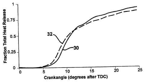
particulate and NOx emissions.
BEST MODE FOR CARRYING OUT THE INVENTION
The pi-ocess of this invention consists of a combination of three elements
that 30
provide and maintain a catalytically active surface on the combustion-exposed
parts of an
internal combustion engine:
CA 02321457 2000-08-17
WO 99/42710 PCf/IJS99/03637
-7-
1.)
A durabie, thermally insulating coating of combustion chamber parts is
required
to raise the combustion facing film surface temperature to a catalytically
active region
above 450 C. This can be. accomplished either with a thin L 0.1 mm) zirconia
coating
or a silica aerogel coating. Pre-applied ceramic or thermal barrier coatings
are effective,
and can maintain the temperature in the required range during stable operation
of the
eagine, such as when the engine is warmed-up and is operating at near
temperature
equilibrium.
In the alternative, a suitable coating can be established by lube oil ash or
the
addition of combustible, ash forming materials to the fuel, such as
tetraethylorthosilicate.
Additions to the fuel are delivered into the engine in the combustion charge,
which is
defined to be fuel or fuel mix delivered into the combustion chamber through
valves, fuel
injectors, or like engineered delivery systems. Notably, materials entering
the combustion
chamber via ring blow-by are not considered to be components of the combustion
charge.
Instead, such blow-by materials are considered to be contaminants. Due to
tighter ring
tolerances in modern engines, increasingly less ring blow-by occurs. Indeed,
such tighter
tolezances have necessitated the present invention.
2.) A cataiytically active moiety such as, for example, platinum or iron, is
dispersed in, or preferably on, the combustion facing surface of the
insulating coating, or
is supplied simultaneously with the coating. Nanophase iron from ferrocene or
nanophase
platinum can be applied either simultaneously with the coating or
subsequently. An
effective engine conditioning dose of ferrocene should range from 5 ppm to 500
ppm by
weight based on fuel.
3.) After assembly of the catalyticaIly coated parts into an engine, or in
situ
establishment of the coating into the engine, it is necessary to continuously
provide a low
level of catalytic precursor to the engine so that the catalytic activity can
be maintained.
One example of a suitable precursor is 25 ppm by weight of ferrocene in fuel.
An
effective range of ferrocene maintenance dose is 5 to 60 ppmw. Application can
be
accomplished by a variety of techniques, such as those disclosed in U.S.
Patent 5,235,936
or 5,113,804, incorporated by reference herein for such teachings. It is
suitable to deliver
the ferrocene in the engine's air intake stream by sublimation or evaporation.
In addition,
the ferrocene or other catalytic metal can be applied by continuous liquid
fuel treatment.
CA 02321457 2000-08-17
WO 99/42710 PCT/US99/03637
-8-
Ferrocene is a useful additive to improve combustion efficiency in internal
combustion engines, whether of the spark ignition type, i.e, a gasoline
engine, or the
compression ignition type, i.e, a diesel engine. It has been observed that a
relatively long
period of time is required to develop improved performance. In highway
testing, both
gasoline and diesel engine equipped vehicles have been found to require
consumption of
large volumes of ferrocene treated fueL In light duty engines, about 120
gallons of arated
fuel is required, treated with ferrocene at 25 ppm, to achieve a 10% increase
in fuel
economy. In heavy duty engines in efficient service, as much as 6000 gallons
of treatied
fuel is required.
A reseanch program with a small gasoline engine confirmed such on-highway
results. In addition, it showed that increasing ferrocene dose by as much as 5
times, to
125 ppm, results in a substantial 5 fold reduction in the amount of fuel
required to provide
full combustion efficiency improvement. Nevertheless, at this treatment rate
of 125 ppm,
24 gallons consumption still is required, requiring at least 10 hours of
operating time. This
same test showed that a 20 fold increase in ferrocene dose to 500 ppm reduced
the fuel
economy benefit by 759'o from the standard dose case. Thus, immediate,
substantial and
reliable engine performance enhancement, required for emission certification
and
commercialization, is not possible with this technique.
A small, 24 cc, two stroke gasoline powered water pump was used to demonstrate
the performance two stage feirocene tneatment. Repeated tests with this engine
in a water
recirculation set-up producing a constant 6 gpm water flow have shown it is
capable of
repeatable operation Of equal nnportance, disassembly, cleaning of the piston
face to a
clean and polished condition, reassembly and rerunning the engine does not
change the fuel
consumption rate in the unmodified or baseline state. Fuel consumption is
equated to
engine efficiency and is the only dependent perfonnance variable which is
measured in this
test.
This engine was used to demonstrate that ferrocene fuel treatment with engine
conditioning provided an 11.3% re.duction in fuel consumption, which was
durable for 60
minutes of additional operation using 25 ppm ferrocene in the fuel. The engine
was
operated for 60 minutes at a 10 fold increased ferrocene dose, i.e., 250 ppm
relative to fuel
weight for 60 minutes, then subsequently at 25 ppm to maintain the coating.
CA 02321457 2000-08-17
WO 99/42710 PCT/US99/03637
-9-
A subsequent test run under identical conditions and control with equivalent
iron
levels in the fuel, i.e., 75 ppm iron for 60 minutes followed by continuing
operation at 7.5
ppm iron in fuel. This test used an iron soap, which is not a catalyst
precursor for this
internal combustion engine application. In the first test immediately after 60
minutes high
dose operation, the use of iron soap caused an initia17.89b increase in fuel
consumption
rate. This is to be expected because a high surface area, non-catalytic
surface coating will
increase the normal combustion termination reaction at the combustion chamber
walls
reducing efficiency and increasing fuel consumption to maintain the fixed 6
gpm water
recirculation rate.
In one reduction to practice of this invention, a piston which had been run in
the
engine to establish its baseline performance was cleaned down to bare
aluminum, that is,
new, unused condition, and submitted to a sol gel coating process to generate
a platinum
containing silica aerogel coating with the following coating specifications:
A.) A high surface area, low density silica aerogel coating -- preferred to be
a 300
to 500 square metersJgram surface area as measured by BET nitrogen absorption.
B.) The coating is to contain 10% to 20% by weight of a nanophase dispersion
of
platinum particles.
C.) The coating should be 500 A or more in thickness.
When this coated, clean piston was reinstalled in the engine, the immediate
perfoimance was at a 5.1% reduced rate of fuel consumption. Notably, only the
piston
face was coated, while the fire deck was not. The coated area is about 50% of
combustion
chamber surface area. The result was equivalent to the post-conditioning,
fully catalytic
performance achieved earlier using ferrocene. This result proves the efficacy
and necessity
of employing the first and second elements of the invention. According to the
invention,
the first element provides a high thermal inertia surface coating. The second
element
provides a catalytic moiety dispersed in the nanophase size range, in or on
the surface
coating.
The catalytically coated piston was then operated for an additiona160 minutes
with
no added catalyst precursor in the combustion chamber charge. The
catalytically enhanced
efficiency was found to have fallen off by 34% in these 60 minutes, confirming
the
requinement for continuous use a catalyst precursor to maintain durable
catalytic activity.
CA 02321457 2007-02-13
-10-
In conti-ast, the pi-evious feirocene test, in which the fen-ocene fuel
treatment at 25 ppmw was
continued for 60 minutes of post conditioning opel-ation, showed no loss of
catalytic
combustion enhancement. This conti-ast proves the necessity of the third
element of the novel
process of this invention, namely: continuous supply of a catalyst precursor
to the engine to
maintain the catalytically improved efficiency of combustion.
A catalytic surface treatment inside a combustion engine can be produced by
traditional wet chemical processes, or generated in situ by fuel composition
modification. The
disadvantage of such processes is that they require high tempei-ature and high
thermal flux
resulting from fully developed combustion processes in the engine in order to
achieve their
catalytic benefits. By way of example, other known processes for depositing
thin metallic
films include chemical vapoi- deposition, flame spray or plasma jet coating.
These processes
can develop a catalytically active surface that is amoiphous, as contrasted to
coherent or
microscopically unifoi-m coatings applied by traditional coating technology.
A thin film coating is preferred for application of a catalyst to improve
combustion.
Adequate catalytic activity is achieved or enhanced by a highly ii-i-egular
surface of at least about
l 00 angstroms to an approximate ma.ximum of about 500 microns. This type of
coating can
provide adequate catalytic activity at temperatures below 250 C. The coating
can be
accomplished by a two step process in which an amoiphous sui-face texturing
material, such a
silica aero gel, is fitst deposited, followed by the catalytically active
metal coating. The two
steps can be combined into a single stage pi-ocess with mixed
substratelmetallic components.
This type of coating can be applied to the combustion surfaces of a new
internal combustion
engine. Thus, an effective substrate/catalyst coating can be created much
sooner and with
greater i-eliability than with establishment of a stable combustion pattern,
which typically
i-equires 10 to 600 hours of operation.
One example of a suitable substrate is silica of high surface area or
roughness. A
desirable surface area is 300 to 500 square metei-s pei- gram measured by BET
nitrogen
absorption. A suitable thickness of this coating is in the approximate range
fi=om 100 to 250
angstroms. The silica coating may contain a metallic element. Prefen=ed metals
are platinum or
iron. The desired concentration of the metal is 20% for a 100 angstrom film or
10% for a 250
angstrom film.
CA 02321457 2000-08-17
WO 99/42710
PCT/US99/03637
-11-
EXAMPLE 1
Overview -- This example describes an experimental protocol designed to answer
whether the ferrocene treatment technology would be effective with small, two
cycle
gasoline engines where lubricant is added to or with the fuel to maintain
above port
lubrication.
A program of engine conditioning has been conducted and evaluated for its
ability
to increase efficiency in internal combustion engines. One aspect is creation
of catalytic
surface activity. For this purpose, two cycle gasoline engines seemed
particularly subject
to enhanced performance. Two reasons for this expectation are (1) the shorter
duration
power stroke available in two cycle combustion, which could benefit from
reduction of the
combustion retarding effect of the wall quench; and (2) the fuel additives
used in the
program iunprove lubrication quality and reduce particulate emissions.
This program used a small 24 cc, 1.3 horsepower water pump. The pump was set
up to deliver a fixed 6 GPM flow rate of water and the fuel flow required to
maintain that
output was measured. It was necessary to adjust discharge pressure to
accommodate
differences in combustion chamber/piston/ring tolerances as the five rebuilds
required
during this program were conducCed.
The results of the program demonstrated:
-- Baseline fuel flow stabilized after a 5 hour break in period.
-- Engine conditioning with ferrocene could be completed in 60 minutes.
-- The conditioned engine required 30% less fuel to maintain the 6 GPM water
flow.
-- Quadiupling the conditioning dose of ferrocene decreased efficiency
improvement by 50%.
-- Substitution of an altennative iron catalyst for ferrocene yielded no
significant
change in fuel flow from the untreated baseline fuel consumptdon.
The ferrocene engine conditioning develops a catalytic coating on the piston
face
and combustion chamber head. This catalytic iron coating changes the normal
combustion
quench wall reaction to a combustion promoting or, at least, neutral surface
which results
in a net increase in combustion efficiency.
Other evaluations of this engine conditioning technology showed effectiveness
in
CA 02321457 2000-08-17
WO 99/42710
PCT/US99/03637
-12-
both automotive gasoline and diesel engines. The effectiveness (% improvement)
seems
similar in both types of equipment with engine size, not fuel/combustion type
being the
primary variable. This similarity of result with both premixed (gasoline) and
diffusion
(diesel) combustion regimes lends support that the effectiveness is
attributable to surface
catalytic factors. The benefits of ferrocene observed with gasoline engines
are: increased
octane; increased MPG - usually about 10%; reduced HC and CO emissions;
reduced
combustion chamber deposits; and reduced valve wear. The diesel engine
benefits are:
increased MPG -- usually about 5 to 10%; increased engine life - usually 40%;
decreased
deposits on combustion chamber, piston ring grooves and valves; decreased lube
oil
consumption;
and decreased particuiate emission -- usually 40%.
Exoerimental Procedure -- An initial investigation was focused on the smallest
and
presumably least efficient engine and limited to investigation of combustion
efficiency as
recorded at constant load fuel consumption. A Diawa GP 25 water pump was
chosen as
the experimental engine. It features a 1.5 cubic inch (24.1 cc) displacement
developing
1.3 HP at 7,500 RPM, a 6.3:1 compression ratio with a float type carburetor.
The
laboratory set-up used a 55 gallon water reservoir, discharge water flow
meter, pressure
gauge and head adjustment valve with temperature of fuel, recirculating water
and intake
air as well as engine.exhaust being measured. The pump was used to recirculate
the water
to the reservoir against a constant head (31 to 35 PSI) at a constant flow
rate (6 gallons
per minute). The fuel flow required to maintain this output was continuously
measured
with a flow meter. The pump was found to be stable in operation for any given
piston/ring/liner-head rebuild but significantly variable between rebuilds.
Two initial baseline runs demonstrated that 5 hours of operation were required
to
stabilize performance which then remained stable (constant fuel flow at
constant water
flow and discharge pressure) for up to 11 hours. This experimental apparatus
was then
used to investigate the effectiveness of feTocene technology in this small two
cycle
gasoline engine.
Exnerimental Plan - Two runs with untreated fuel were conducted to determine
the
length of time required for this engine and test set-up to stabilize fuel
consumption. The
first fernncene test was conducted using a five fold increase in dose of the
catalyst to
CA 02321457 2000-08-17
WO 99/42710 PCT/US99/03637
-13-
accelerate engine conditioning. This five fold dose was run for 60 minutes
followed by
triplicate tests conducted at the end of this test run. The fourth run
evaluated a 20 times
dose rate used for only 5 minutes to determine if further acceleration of
engine
conditioning was possible. The fifth test looked at two different effects.
First, multiple
disassembly/re-assemblies of the same combustion chamber, piston and rings was
conducted to determine the ability to reproduce fuel consumption results after
disassembly.
Finally, a different iron catalyst was used to determine if the catalytic
effectiveness of
ferrocene could be duplicated. The experimental results are shown in Table 1:
Table 1 - Test Results
Run No. 1 2 3 4 5a 5b
Ambient 58 46 60 62 48/65 66
Temperature
( C)
Water 68 75 85/67 88 81/69 73/79
Temperature
( C)
Exhaust 684 751 613 584/903 992 911
Temperature
Water Flow 6 6 6 6 6 6
GPM
Water Pressnrel 35 35 31 33 35 34.5
Fuel Flow 5.29 5.01 7.96 7.15 5.532 5.912
Average
Standard .19 .53 .07 .25 .18 .28
Deviation
Treated Fuel 5.27 6.15 5.722 6.043
Flow Average
Standard .09 .25 .13 .23
Devi.ation
CA 02321457 2000-08-17
WO 99/42710 PCT/US99/03637
-14-
Table 1 Notes:
1 Adjusted to achieve 6 GPM flow rate.
2 Three serial rebuilds using same parts, designated 5a1 = 5.53; 5a2 = 5.72;
5b1 = 5.91.
3 Test Result with iron soap addition is 5b2 = 6.04.
Conclusions --
1) A five hour break-in is required to stabilize fuel consumption.
2) This small engine is very sensitive to combustion chamber/piston/piston
ring
match as is indicated by the variability in broken-in fuel consumption across
tests 1
through 5.
3) A 60 minute run at a 5 x dose of ferrocene (Run 3) was sufficient to
condition
the engine as is indicated by the substantial reduction in fuel consumption
after
conditioning.
4) There was no time trend to the continued use of Ferrocene treatment for 60
minutes after the conditioning dose was terminated so conditioning was
complete in 60
minutes at 5 times dose rate.
5) The 20 times conditioning dose (Run 4) may have been too high since the
performance improvement was smaller (14% versus 34% in Run 3 at 5 times) and a
second 5 minute run at 20 times dose resulted in a 2 standard deviation
increase in fuel
consumption.
6) Repeated re-assembly of the same engine parts (Tests 5a1 baseline, 5a2
reassembiy, 5b2 reassembly) did require as much as 60 minutes to reseat but in
each case
(repeated twice) fuel consumption returned to the baseline value for that set
of parts.
7) The altemative iron catalyst (Test 5b2) produced no significant change in
fuel
consumption, confirming the unique activity of ferrocene in generating this
catalytic
coating which improved efficiency.
F.XAMPLE 2
Overview -- This example describes the effectiveness of femcene in fuel to
develop a catalytic surface in the combustion chamber of a single cylinder
diesel engine.
The testing involved two phases, each with a different engine configuration.
In the first,
the engine was evaluated with normal combustion deposits from previous
operations, and
with an aluminum piston. In the second phase, a new piston was installed,
coated with a
CA 02321457 2007-02-13
-15-
500 micron thei-mal bar-rier coating of plasma sprayed zii-conia (PSZ). The
second test used
the ol-iginal cylinder liner, piston rings, and head. However, all combustion
deposits were
i-emoved and the cleaned parts had no thermal barrier coating.
Test Plan -- The initial plan called for the engine to be conditioned by use
of fuel with
250 ppm fen-ocene, for 240 minutes, followed by operation with 25 ppm
ferrocene. Because
the engine was aii- cooled, a water spray was directed against the head and
cylinder linei- to
achieve lower block tempei-atui-es similar to water cooled engines.
As a preliminal-y evaluation of the engine, two i-uns wei-e to be conducted
with
untreated 2-D diesel fuel to determine baseline characteristics. The initial
high dose fei7-ocene
ti-eatment at 250 ppm was coritinued until pal-ticulate matter fell to a
stable level. Then, the
feiTocene level was i-educed to 25 ppm and the engine were tested for the same
baseline
characteristics, which include emissions level and heat release i-ate.
Then, the engine was prepared for the second phase of the test. The original
aluminum
piston was replaced with the new thei-mal baiY-ier coated (TBC) piston, and
combustion
deposits and catalytic coating fi-om initial testing were removed fi-om the
fire deck (head and
valve faces). The engine was retested, again deteimining baseline
characteristics, conditioned
with the high dosage of ferrocene, and tested while running with low dosage of
fen-ocene.
Testing -- The testing with the aluminum piston and established combustion
deposits
was conducted foi- 50 minutes to establish baseline. The baseline data is
shown in the region
labeled D2 on the left hand graph of Fig. 1, fi-om time 0 to time 50 on the
time axis. Fuel was
switched to 250 ppm fei7-ocene without stopping the engine and continued for
390 additional
minutes. The following day, the engine was stai-ted with 250 ppm fei-rocene
fuel and run for
180 minutes. The high dose data is shown in the region labeled 250 ppm on the
left hand graph
of Fig. 1, fi-om time 50 to time 620 on the time axis. On a third day, the
engine was started with
25 ppm ferrocene fuel and 1-un for 132 minutes. On a fourth day, the engine
was started with 25
ppm fuel and run for 85 minutes. This low dose data is shown in the i-egion
labeled 25 ppm on
the left hand graph of Fig. 1, from time 620 to time 817 on the time axis. The
disconnected
final thi-ee data points on the graph, appi-oximately at time 800 minutes, are
believed to reflect a
malfunction in one of the instruments.
CA 02321457 2000-08-17
WO 99/42710 PCT/US99/03637
-16-
In the second phase testing with the TBC piston and cleaned fue deck, the
engine
was run for 60 minutes to establish baseline. This baseline data is shown in
the region
labeled D2 on the right hand graph of Fig. 1, from time 1000 to time 1060 on
the time
axis. Fuel was switched to 250 ppm fenocene without stopping the engine and
continued
for 250 additional minutes. The high dose data is shown in the region labeled
250 ppm
on the right hand graph of Fig. 1, from time 1060 to time 1310 on the time
axis. The
following day, the engine was started with 25 ppm fea-ocene fuel and run for
75 minuties.
The data from this low dose test is shown in the region labeled 25 ppm on the
right hand
graph of Fig. 1, from time 1310 to time 1385 on the time axis.
Exnerimental Results -- Data recorded during the test included exhaust gas
emissions, particulate emissions, cylinder pressure, and engine performance.
The indicated
specific fuel consumption (ISFC) performance of the engine during the aluminum
piston
tests; the fuel rate, as measured with a mass flow meter, and power absorbed
were
determined and compared. The data showed a stable load, stable fuel flow and
stable fuel-
air-ratio (FAR). ISFC showed an initial incnease (3.9%) followed by a clear
decreasing
trend. The same data on-ISFC for the TBC piston test also showed an ISFC
increase of
3.9% when fuel was switched from untteated to treated at 250 ppm ferrocene.
This jump
is followed by an apparent linear decrease until the engine shutdown at the
end of day 5.
As noted above, Figure 1 shows the variation of Indicated Means Effective
Pressure
(IlVIEP) and Indicated Specific Fuel Consumption (ISFC) with Time Shown as
Fractional
Changes from Mean Value of the Variable. The left hand side of the graph shows
the
ISFC data points (10) and IIVIEP data points (12) for the aluminum piston, and
a trend line
(14) is plotted for the ISFC data. The right hand graph shows ISFC data points
(20) and
I1Vfl3P data points (22) for the thermal barrier coated piston, and a trend
line (24) is plotted
for the ISFC data.
The test data showed that an immediate effect of switching to 250 ppm
ferrocene
was a 3.9% increase in ISFC. Both engine configurations responded similarly,
indicating
this increase in ISFC was homogeneous vapor phase combustion quench effect
that is a
direct result of the high dosage of feirocene.
The data also showed a linear decrease in ISFC in the aluminum piston test
during
60 to 310 minutes of operation. However, there was no significant ISFC effect
in the 325
CA 02321457 2000-08-17
WO 99/42710 PCTIUS99/03637
-17-
minutes ferrocene operation with the TBC piston, nor was such effect expected.
The
coating on the TBC piston was not applied to head and valve faces because
previous
testing had shown that active wall catalyst did not develop on bare metal
combustion
chamber surfaces. The TBC piston surface represents about 58% of the exposed
combustion chamber surface at top dead center. Consequently, the net ISFC
change
expected is 0.045 x .58 x 250 = 6.53 or less than two standard errors (les.s
than 959'0
signif'icance). On the other hand, averaging the two high-low data pairs
observed in the
85 to 300 minute TBC test time period gives a 98% significance slope estimate.
The
decreasing ISFC trend slope estimates are: -0.0266 smoothed data versus -
0.0269 raw
data, which is 61% of the aluminum piston test slope during the active 250 ppm
conditioning period of 85 to 370 minutes. Consequently, the thermal banier
coating
applied only on the piston is shown to produce improvement proportionate to
the 58%
coated surface area in the combustion chamber at TDC. Thus, the ISFC trend
appears to
result from development of a wall catalyst derived from ferrocxne combustion.
In the
aluminum piston engine, the coating developed in the presence of thermall.y
insulating
combustion deposits on the piston face, head and valve surfaces; while in the
TBC piston
engine, the coating developed only in the presence of thermal barrier
coatings.
A sunilar ratio of improvements was observed in data from a Condensation
Nuclei
Counter (CNC) that measured the concentration of particles in the diesel
exhaust. With
the aluminum piston and full normal lube oil insulating base, a 47~'o
reduction in particle
numbers was observed. With the TBC piston, the engine produced a 31% reduction
in
particle numbers, which equates to 66% of the reduction found with the
aluminum piston.
This result is well within test measumment variability of 13% of the 58%
surface
coverage of the TBC.
CA 02321457 2007-02-13
- 18-
Table 2 - Indicated Specific Fuel Consumption (ISFC) -- Aluminum Piston
', I T
M nut s Test Segnient Initial Final Slope Significance
- --- -_ _ - - _- _- _ -- ,
0 50 Baseline T 210 210 None
85-370 Conditioning at j 215 203 -0.043 >99%
250 ppin
I
Over Conditioning >99%
340-605 at 250 203 213 +0.028 >ppm
630-800 Reco~ditiolnning at 206 198 -0.046 >95%
pp
The pai-ticulate numbei- concentl-ation ti-ends for the aluminum piston test
showed
a substantial inci-ease in number of particles found with the addition of 250
ppm
fen-ocene. The inci-ease of pai-ticles between 5.6 and 32 nm was by a factor
of 86 foi- the
high dosage of fen-ocene and by a factor of 6.3 foi- the low dose fel-rocene.
Such tiny
pai-ticles are believed to be foi-med by volatilization of metal compounds dui-
ing the
combustion stroke, followed by nucleation during expansion stroke. If the tiny
particles
ai-e few in number, they can be absorbed onto soot, in which case few nuclei
would be
formed. Evidently, the feiTocene produced a lai-ge number of nuclei. FeiTocene
is 30%
iron by mass, con-esponding to 7.5 and 75 ppm iron by mass in the fuel.
Equilibi-ium
calculations suggest the 250 ppm feirocene dose should produce 10.3 mg of iron
sulfate
per standard m" in the exhaust. The detected tiny pai-ticles would account for
only about
10% of the ferrocene iron. Thus, the remainder appears lost thi-ough other
channels,
including deposition on combustion chambei- sui-faces.
The number concentration of particulates deci-eased during engine
conditioning. These
changes are atti-ibutable to the subtle changes in heat i-elease caused by
continued opei-ation at
the high fen=ocene dose. A 0.6 ratio of reduction in particle numbei-
concentration change was
noted in the two tests during the high dose conditioning periods. This i-
eduction i-atio is similai-
to the .57 area coverage of the TBC and similar to the ISFC slope comparison.
The formation
of ultra fine particulates is extremely sensitive to
18
CA 02321457 2000-08-17
WO 99/42710 PCT/US99/03637
-19-
combustion timing, so the substantial changes seen in both of these tests
provide additional
evidence that fenocene engine conditioning does modify combustion
characteristics.
A repeatability study of heat release rates measurements is presented in Table
3,
showing measured peak pressure and calculated peak temperature with the crank
angle at
which each occurred for four separate baseline W.M. The repeatability study
suggests
excellent repeatability of combustion pressure derived heat release results.
Variation is
sufficiently small that the range of 10% bum angle is only 6.4 to 6.6 CAD; 30%
burn
angle range is 8.1 to 8.3; 50% is 9.6 to 9.8; and 70% is 12.4 to 12.8.
TABLE 3- Baseline Repeatability of PressureJTemperature Re.sults
Day of Test Peak At CAD IMEP Peak At CAD
Pressure Temperature
PSI R
5/31 1043 10.5 66.5 3862 15.5
5/31 1040 10.5 66.3 3851 15.5
611 1039 10.5 67.8 3844 15.5
6/1 1037 10.5 67.8 3845 15.5
6/1 1035 11.0 67.6 3844 17.5
6/2 1035 10.5 67.1 3838 17.5
6/2 1027 11.0 67.7 3838 15.5
6/4 1041 11.0 66.8 3864 15.5
6/4 1042 10.5 67.8 3823 15.5
64 1038 11.0 67.3 3840 15.5
614 1041 10.5 67.2 3835 15.5
Average 1038 10.7 67.3 3844 15.9
Standard 4.5 0.25 0.56 12 0.81
Deviation
Table 3 Notes: IlVlEP = Indicated Mean Effective Pressure
Table 4 shows the time sequence and peak temperatare and pressure performance
during the entire 175 minutes of operation of the aluminum piston test
configuration on
Day 2 (June 5) at a 250 ppm dose of ferrocene.
CA 02321457 2000-08-17
WO 99/42710 PCT/US99/03637
-20-
Table 4- Second Test Day (June 5) Pre.ssure/Temperature Results
Aluminum Piston at 250 ppm Ferrocene Dose
Cumulative Peak @ IMEP Peak @ ISFC
Running Pressure CAD Temperatare CAD (kg/kWhr)
Time (min) PSI R
460 1014 12.0 68.9 3871 16.5 .162
485 1016 12.0 69.0 3881 16.5 .162
500 1009 11.5 69.8 3 834 16.5 .165
515 1014 11.5 68.1 3811 16.5 .164
530 1013 12.0 68.5 3858 16.5 .163
Avg.
SSE 1013 2.6 11.8 68.9 .6 3851 28 16.5- .163
0.3 .0013
545 1015 11.5 69.1 3822 15.5
560 1013 11.5 68.6 3788 15.5
575 1016 11.0 69.5 3765 15.5 .161
590 1018 11.5 68.9 3795 15.5
605 1016 11.5 68.7 3828 16.5
The oxides of nitrogen show a 3% drop after an initial period of stability
from 440 to 480
minutes with the minimum NOx occurring at 560 to 575 minutes followed by an
increase.
Exhaust temperature wanders for the first 85 minutes (440 through 525
minutes). The
average exhaust temperature in this time frame is not significantly different
from the Day
1 average. Between 515 and 560 minutes, however, the exhaust temperature drops
significantly (855 F versus 874 F on Day 1) and then increases back up to 874
F at 605
minutes. Inspection of the calculated peak temperature performance in this
same time
frame in Table 4 shows stable performance for the first five measurements.
Subsequently,
from 545 to 590 minutes there is a full degree tuning change and a significant
decrease
in peak temperature with the minimum peak temperature corresponding to the
minimum
NOx point at 575 minutes.
Figure 2 shows heat release plots corresponding to the runs of Table 4. Line
30
plots the beginning of NOx decrease at time 485 minutes. Line 30 is the
pressure traae
pmsented as the calculated total fractional heat release, versus crank angle
degree, for the
CA 02321457 2000-08-17
WO 99/42710 PCT/US99/03637
-21-
non-catalytic base case performance of the aluminum piston engine, at time 485
minutes
into the test shown in Figure 1. This heat release profile is taken during the
time frame
when the NOx emissions from the engine were stable at the base line level.
Line 32
shows the same pressure trace measurement taken at 560 minutes, which is the
time of
minimum peak in-cylinder pressure and corresponds to the minimum NOx emissions
from
the engine. It should be observed that the ISFC shown in Table 4 for this
series of data
points with the active wall catalyst is lower than the base line ISFC for the
data points
nearest to the 485 minute profile plotted in Fig. 2. Consequently, Fig. 2 is a
graphical
confumation of the novel and unique wall catalyst activity accelerating early
phase heat
release, from 5% to 60% total heat release, which improves power output and
reduces fuel
consumption while simultaneously reducing maximum in-cylinder temperature, as
shown
in Table 5, which is the deterinining factor for reducing NOx emissions.
This data shows no significant change for the first five data points. The next
three
data points (560, 575 and 590 minutes) show a snbstantial decrease in the
crank angle at
30% burn completion (30% bum angle moves from 9.2 .08 average from 460
through
530 minutes to 8.5 CAD at 575 minutes) with no significant change in the 109'a
or 60%
burn angle. Figure 2 shows this shift in early heat release pattern without an
apparent
ignition timing change and presents the contrast between the heat release
profiles at 485
minutes and 560 minutes as measured on day two. A developing flame front does
not
make significant contact with the combustion chamber walls until after 5 CAD
after top
dead center. Thus, wall catalytic effects do not change ignition
characteristics, as is shown
in the 3 to 6 CAD results in Figure 2. The substantial acceleration of the
heat release in
the 30% to 40% combustion completion range in the 560 minute profile
apparently allows
ahis earlier pressure increm on the piston to be extracted more efficiently as
work. Tbis
would be expected to improve ISFC. Plots for the data points of 590 and 605
show
consistent movement back towards the 460 through 530 minute average profile.
This again
is consistent with the return of exhaust temperature to the higher average of
Day 1.
Consequently, it is believed that the wall catalytic activity reaches an
observable maximum
at 575 minutes.
Conc lusions -- The test program of Example 2 suggests that ferrocene fuel
taeatment results in the development of a catalytically active wall coating
which may allow
CA 02321457 2000-08-17
WO 99/42710 - PCT/US99/03637
-22-
in-cylinder heat release rate shaping. The use. of ferrocene additive
influences the
combustion process in a diesel engine, where the full effect of the additive
takes several
hours to develop.
Thus, both surface modification with a high thermal inertia coating (24 cc
gasoline
water pump and TBC diesel test results) and nanophase catalytic surface
structure are
necessary precursors to simple use of fenocene for combustion efficiency and
emissions
improvement. The performance of the additive is strongly dependent on the
conditioning
process.
The foregoing is considered as illustrative only of the principles of the
invention.
Further, since numerous modifications and changes wiil readily occur to those
skilled in
the art, it is not desired to limit the invention to the exact construction
and operation
shown and described, and accordingly all suitable modifications and
equivalents may be
regarded as falling within the scope of the invention as defmed by the claims
that follow.