Note: Descriptions are shown in the official language in which they were submitted.
CA 02321492 2000-08-18
WO 99/42742 PCTICA99100071
Engine Balance Apparatus
Field of Invention
This invention relates to a balancing apparatus for a vehicle engine and more
particularly
to a twin counter-rotatingbalance shaft assembly for a four cylinder in-line
internal combustion
engine, which reduces engine vibration.
Background of the Invention
Internal combustion engines of the reciprocating type have movable portions,
which
to become off balance during the operation of the engine. This causes
vibration and noise. The
vibration and noise are objectionableto the passengers of the vehicle and also
cause degradation
to engine parts, increasing component wear and fatigue.
Existing engine balance mechanisms seek to solve these problems, but are
typically heavy,
large, and produce considerable drag on the engine. Typical balance mechanisms
use large,
complicated cast housings to exclude oil from some areas and allow the oil to
flow freely to other
areas. The size and complexity of existing balance shaft mechanisms also
increase their cost.
In addition, existing engine balancing mechanisms tend to be noisy due to the
meshing of steel
gears.
A conventional balancing device of this type typically includes a pair of cast
or forged
steel balance shafts which incorporate un-machined, as-cast eccentric weights
as well as machined
journal bearing surfaces or roller bearing surface seats. The bearings are
held in split housings,
typically line-bored after pre-assembly. Since the balance shafts typically
turn at over 12,000 rpm
(twice the engine speed), tolerances of the machined surfaces must be closely
held. Thus, these
devices require costly machining steps to achieve accuracy. Further, during
operation of the
engine, the eccentric weights cause shaft deflection resulting in misalignment
between the shafts
and bearing housings. This misalignment is greatest when the engine speed and
bearing loads are
highest, which has necessitated the use of costly, extra-precision bearings or
pressure-fed
lubrication of journals with engine oil.
-1-
CA 02321492 2000-08-18
WO 99/42742 PCT/CA99/00071
Other products which attempt to solve the balance problems, include the
'balancer
apparatus for engine' as described in United States Patent No. 5,305,656. This
unit succeeds in
providing a balancing of the secondary vibration in a four cylinder engine.
However, several
disadvantages of this type of unit still exist. The length and size of such
engine balance
mechanisms require significant modifications to engines, oil pans and nearby
vehicle sub-frames
to allow packaging of the mechanism into the engine. The noise from this and
other engine
balance mechanisms are a source of passenger annoyance and may even be
comparable to the
engine vibration noise, which existed prior to the installation of the engine
balance mechanism.
Significant inefficiency of engine balance mechanisms still exists resulting
from parasitic losses
1o in the gears and particularly, the counterweights. Both the gears and
counterweights may be
partially or fully submerged in engine oil during their operation and
considerable form drag exists
from the counterweights of current engine balancing mechanisms. The cast
housings in current
engine balance mechanisms are large and heavy.
~ 5 Other conventional balance shaft pairs typically incorporate sprockets and
chains or steel
gears to drive one of the balance shafts via an engine crank shaft drive gear.
The first balance
shaft drives the second balance shaft by the steel gears to produce counter-
rotating motion.
During operation, gear noise and rattles occur which are caused by gear
meshing and torsional
crank shaft vibrations. Counter-measuresto avoid these problems have been
proposed including
2o the use of anti-backlash gears and powder metal steel gears (with improved
internal damping), but
have been only partially successful. Non-metallic gears have also been tried
unsuccessfully, due
to high cyclic stresses caused by the torsional vibration of the crank shaft,
transmitted through the
gears, resisted by the high inertia of the rotating balance shaft components.
25 Summary of the Invention
The disadvantages of the prior art may be overcome by providing a light
weight, compact,
low drag, low cost, relatively quiet engine balance mechanism.
3o It is desirable to provide a balancing apparatus for suppressing vibrations
generated by
unbalanced inertial forces of the components of the engine.
-2-
CA 02321492 2000-08-18
WO 99/42742 PCT/CA99/00071
According to one aspect of the invention, there is provided driven gears,
which are in plane
with the counterweights. The apparatus makes use of the space within the body
of the gears, and
makes the material within the plane of the gears contribute to the
counterbalancing effect of the
counterweights. This dual use of the gear space provides for a shorter engine
balance apparatus.
s This allows for flexibility in packaging the engine balancing apparatus into
a multitude of engine
configurations.
According to another aspect of the invention, the counterweights, which are
typically
longer in the axial direction than the gears, support the gears anywhere along
the length of the
1 o counterweights. This allows flexibility in packaging the position of the
driven gears relative to
the end brackets and the engine bull gear in the engine balance apparatus.
According to another aspect of the invention, the counterweight consists of an
axisymmetrically shaped portion, typically of steel, which contains an open
pocket, or pockets,
15 for a low-density filler material. This allows the counterweight to remain
round, reducing form
drag and also ensures that its centroid is offset from the center axis, thus
providing the mass offset
which is desirable in a counterweight. Also provided for, is the addition of a
second pocket, or
pockets, in the counterweight, which may contain a material or materials of
higher density, such
as lead. This enhances the ability to increase the counterweight mass offset
in a given package
2o space, keeping the size of the counterweights, and thus, the apparatus to a
minimum.
According to another aspect of the invention, a counterweight, which may be
separate
from the driven gears of the apparatus; is axisymmetric. It consists of two or
more portions, the
first of which has an unsymmetrical form. The second is a covering material of
a different
25 density, which effectively makes a fairing over the more conventional shape
and makes the
counterweightassembly axisymmetric, the simplest form of which would be
cylindrical. Other
materials of varying densities could be included to tune or optimize the mass
offset.
According to another aspect of the invention, small, light weight, end
brackets support the
3o engine balance center shafts, which supportthe counterweightsand gears.
These shafts are bolted
to the end brackets to provide structural coupling between the two end
brackets. The end brackets
-3-
CA 02321492 2000-08-18
WO 99142742 PCT/CA99/00071
are considerably smaller than most balance shaft brackets or housings for an
engine balancing
apparatus of similar size.
According to another aspect of the invention, a thin, light weight metal or
plastic cover is
provided between the two end brackets for the purpose of controlling the
amount of oil that is in
contact with the gears and counterweights in the balance shaft apparatus. This
cover may be held
in place by conventional screws or other fasteners and may include a bonding
or sealing agent at
the interface to the end brackets to help prevent engine oil leaking into the
enclosed area. The end
brackets and cover form an enclosure from below and from the sides of the
apparatus, while
leaving the top area above the gears arid counterweight open. Typically, an
engine balance
apparatus of this nature is fixed to the engine, below the crank shaft, in the
oil pan area. The
apparatus would be significantly submerged if no covering were used to exclude
the oil from this
area. A small hole, or holes are included in the cover to allow small amounts
of oil to enter the
gear and counterweightarea to lubricate the gears. This oil is typically
ejected from this area by
flinging off of the gears to outside of the covered area at approximately the
same rate that it is
entering the balance shaft area through the hole or holes in the cover. The
size and number of
holes in the cover allows for tuning the rate at which oil enters the enclosed
area during engine
operation.
2o According to another aspect of the invention, cost can be reduced by using
common parts
in different areas of the apparatus. Typically, shafts and bearings are used
in more than one
location in an engine balancing apparatus. This invention also provides for
the two end brackets
to be common parts; the two counterweights can also be common parts. In the co-
planar gear and
counterweight embodiment discussed, a metallic gear would be pressed onto one
of the
counterweights and a plastic or composite gear would be insert molded onto the
other
counterweight.
According to another aspect of the invention, there is provided an engine
balancing
apparatus which has a housing assembly mounted to a vehicle engine. The
housing assembly has
3o spaced apart endwalls and two parallel extending support shafts connected
to the endwalls. A first
counterweight is rotatably mounted concentrically about a first of the support
shafts. The first
_4_
CA 02321492 2000-08-18
WO 99/42742 PCT/CA99/00071
counterweight has a first gear, a lead filled first void and a phenolic filled
second void
diametrically opposed from said first void. A second counterweight is
rotatably mounted
concentrically about a second of said support shafts. The second
counterweighthas a second gear,
a lead filled third void and a phenolic filled fourth void diametrically
opposed from the third void.
The second gear is in driven engagement with the first gear for counter
rotation therewith. The
first support shaft is positioned relative to the crankshaft of the engine for
drivingly engaging the
first gear. Each of the counterweights has a center of gravity offset from an
axis of rotation
whereby as the counterweightscounterrotate an inertial force is generated
which has a cancelling
effect on inertial forces generated by operation of the vehicle engine.
to
Description of the Drawings
The invention may best be understood with reference to the accompanying
drawings
wherein an illustrative embodiment is shown.
Figure 1 is an isometric view of a balancing apparatus provided in accordance
with
the principles of the present invention;
Figure 2 is a front elevational view, partially broken away, of the apparatus
of
Figure 1;
Figure 3 is a sectional view of the apparatus of Figure 2, along the lines A-
A;
Figure 4 is a sectional view of the apparatus of Figure 2, along the lines B-
B;
2o Figure 5 is an end elevational view of the counterweights of the apparatus
of Figure
1;
Figure 6 is a top plan view of a second embodiment'of the balancing apparatus
of
the present invention;
Figure 7 is a section view of a counterweight of the balancing apparatus of
Figure
6, along the lines C-C.
Description of the Invention
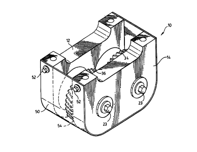
Referring to the drawings, there is shown an engine balancing apparatus 10,
which
embodies the principles of the present invention. The engine balancing
apparatus 10 is
3o constructed and arranged to suppress secondary vibrations in a conventional
four cylinder, in line,
internal combustion engine as disclosed, for example, in U.S. Patent No.
5,305,656. The
_5_
CA 02321492 2000-08-18
WO 99/42742 PCT/CA99/00071
conventional engine includes a rotatable crank shaft and a plurality of
pistons and cylinders for
causing rotation of the crank shaft. As is typical, the crank shaft includes a
helical drive gear.
mounted for rotation therewith, referred to as the bull gear within this
document, of the type
disclosed in U.S. Patent No. 5,305,656.
The balancing apparatus 10 comprises a forward end bracket 12 and the rear end
bracket
14. Typically the balancing apparatus 10 is bolted directly to the engine
block 16 via four
mounting bolts 18 which extend through mounting bores in the ends of brackets
12, 14. The end
brackets 12,14 support the inner shafts 20. Each end 22 of shaft 20 has a
smaller diameter than
1 o a middle portion. The ends 22 extend through bores 24 of brackets 12 and
14. The adj acent bores
24 are offset relative to the upper mounting surface of the brackets 12 and
14. The smaller
diameter ends 22 present shoulders for positioning the brackets 12 and 14 in a
spaced parallel
relation. Bolts 23, via washers 25, engage threaded bores in the ends 22 to
retain the shafts 20 in
place.
The middle portion of shafts 20 each support a counterweight26 and 28. Needle
bearings
30 are mounted between the shafts 20 and the counterweight weights 26 and 28
allowing for
rotation of the counterweights 26 and 28 relative to the inner shafts 20. End
play of the
counterweight26 and 28 is controlled by thrust bearings 32 which retain the
axial position of the
2o counterweight 26, 28 between the end brackets I2, 14.
Counterweight26 has a steel gear 34 which is pressed thereon and counterweight
28 has
a phenolic gear 36, which is molded thereon. Note that a toothed form is
provided on the
counterweights 26, 28 to enhance the attachment of the steel gear 34 and
phenolic gear 36.
During assembly of the balancing apparatus 10, the counterweights 26, 28 must
be arranged such
that the centers of gravity are opposite each other, when the two gears 34, 36
are brought into
operative engagement. This ensures that the counterweights 26, 28 work
together to sum the
inertial forces in the vertical direction and to cancel the horizontal
inertial forces as they rotate in
opposing directions.
-6-
CA 02321492 2000-08-18
WO 99141742 PCTICA99/o0071
Each counterweight 26, 28 has preferably two diametrically opposed voids 42,
44, which
are filled with materials of differing densities. On one side of each
counterweight 26, 28, a
relatively dense material 46, preferably lead, is inserted into void 42. On
the other side, a
relatively less dense material 48, preferably a polymer, such as phenolic
resin, is used to fill the
second void 44. By using the polymer insert 48, the lead insert 46, and the
steel body of the
counterweights26, 28, which itselfhas an offset center of gravity, a large
center of gravity offset
from the axis of rotation can be achieved in the counterweight.
A thin sheet cover 50 of metal, plastic or other suitable material is held
into place by
1o conventional screws 52. Tt is desirable to exclude the engine oil, which
typically resides in the
oil pan and typically surrounds the engine balance apparatus, from engulfing
the gear and
counterweight portion of the apparatus 10. Excess engine oil causes excessive
viscous drag on
the gears 34, 36 and counterweight 26, 28 portions of the balancing apparatus
10. The cover 50
and end brackets 12, 14 form a semi-enclosed area which encloses the gears 34,
36 and the
counterweights 26, 28 on the sides and below. At least one small hole 54 in
the lower portion of
the cover 50 regulates the flow of lubricating oil into the enclosed area. Oil
splash caused by the
gear teeth hitting the enclosed pool of oil, ejects oil from the top of the
enclosed area, preventing
the oil level from raising higher than is necessary to lubricate the gears 34,
36. The enclosure thus
provides an area relatively free from the oil in the oil pan reservoir and
reduces parasitic losses
2o that would result from the gears and counterweights rotating in a viscous
oil environment.
Operation of the invention
The bull gear 40 is affixed to the engine crank shaft and rotates at crank
shaft speed. The
bull gear 40 engages only the phenolic gear 36 because the gear 34 is offset
relative to the
phenolic gear 36. The phenolic gear 36 is sized relative to the bull gear~40,
such that it typically
runs at twice the speed of the bull gear 40. The damping characteristics of
phenolic reduce the
noise produced by the engagement of the two gears 36 and 40. Counterweight 28
rotates at the
same speed as the phenolic gear 36. The phenolic gear 36 also engages the
steel gear 34 which
is caused to rotate at an equal speed, but opposite in direction to the
phenolic gear 36. The
3o damping characteristics of phenolic again reduces the noise generated by
the two gears 34 and 36
running together. The engagement of the phenolic gear 36 to the steel gear 34
causes the steel
_7_
CA 02321492 2000-08-18
WO 99J42742 PCTJCA99/00071
gear 34 and its counterweight 26 to rotate in an opposite sense to the
phenolic gear 36 and its
counterweight28. The opposite rotation of the two counterweights 26, 28
enables them to work
together to sum the respective inertial forces in the vertical direction and
to cancel the horizontal
inertial forces as the centers of gravity remain in opposing orientation in
the horizontal direction.
The resultant inertial forces generated by the two counterweights 26, 28
cancels the secondary
inertial forces generated by the engine pistons and connecting rods. The mass
offset in the
counterweights 26, 28 is provided by the use of differing density materials in
the counterweights
26, 28.
to Referring to Figures 6 and 7, an alternate embodiment is illustrated. In
this embodiment,
the counterweights 126,128 are not integral with the gears 134, I36,
respectively, but are attached
via a hollow shaft 124. The axisymmetric shaped counterweights 126, 128
consist of a plurality
of materials of varying densities. For example, a steel core 142 is combined
with a polymer
fairing 148. The counterweights may be constructed by first machining the
steel core 142 and
I S then molding the polymer fairing 148 onto the steel core 142.
It thus will be seen that the objects of this invention have been fully and
effectively
accomplished. It will be realized, however, that the foregoing preferred
embodiment of the
present invention has been shown and described for the purposes of
illustrating the structural and
2o functional principles of the present invention and is subject to change
without departure from such
principles.
_g_