Note: Descriptions are shown in the official language in which they were submitted.
CA 02321521 2000-08-29
WO 99/47211 PCTNS99/05744
t STATIC ELECTRICITY DISSIPATION IN AIR COMPRESSORS
2 BACKGROUND OF THE INVENTION
3 1. Field of the Invention
This invention relates to compressor fluids, such as those used in air
s compressor systems. and in particular to the dissipation of static
electricity in such
fluid.
2. Description of the Prior Art
s Air compressors and other similar compressors. such as vacuum compressors
9 and refrigerant compressors. use a liquid fluid for cooling, sealing and
lubrication.
to Although this fluid is commonly referred to as "oil." it is more properly a
specially
t t selected organic liquid chosen primarily far its heat exchange
characteristics,
t2 viscosity and lubricity. Examples of fluids used as oil in air compressor
systems
t3 include polyalphaolefin (PAO), polypropylene glycol, polyolester (POE),
diester-
ta based oil, combinations of PAO and diester fluid, petroleum-based fluid,
silicon-
es based oil and severely hydro-treated paraffinic oil. Many of these fluids
have found
tb use in compressor systems after being developed for other applications,
such as
t~ hydraulic fluid for hydraulic systems.
is Some of these fluids, particularly the PAO fluids, were originally used as
t9 coolants in electric transformers. The heat exchange characteristics of PAO
fluids
2o exhibited as a transformer coolant made these fluids a popular choice for
adoption as
CA 02321521 2000-08-29
WO 99/47211 PCT/US99/05744
-2
i oil in air compressors. where they are commonly used today. Because of their
2 development for use in electrical transformers. these fluids are dielectric
fluids. that
3 is, fluids which act as an electrical insulator and prevent am~ transfer of
electricity.
a PAO fluids are sold for use in air compressors under various brand names,
including:
s Sullube 32. sold by Sullair Corporation ofMichigan City. Indiana; AEON 9000.
sold
by Gardner Denver. lnc. of Quincy. Illinois; Quin-Syn series, sold by Quincy
Compressor Division of Coltec Industries of Quincy. Illinois; and Roto Inject
fluid.
s sold by Atlas Copco Air Power of Wilrijk. Belgium.
9 The compressor fluid or oil is used not only for sealing and cooling but
also
to for lubrication. and for this purpose some of the oil becomes suspended in
the air
~ z stream. Air-oil separators are typically used to remove suspended oil mist
from the
tz air stream before the compressed air is discharged. The separator allows
the
13 discharged air to be used without the contamination of oil and provides for
the
14 recovery of the oil so that it can be reused. The air-oil separator is
typically mounted
15 in a housing or tank having a separation chamber through which the air
flows above
I6 an oil reservoir. The separator includes coalescing media through which the
17 discharge airpasses white the oil is separated from the air flow. The
coalescing media
18 is cylindrically shaped and is typically mounted vertically, that is, in
which the axis
19 of the cylindrical coalescing media extends in a vertical direction. The
oil-laden air
2o usually enters the separation chamber from outside the air-oil separator
and flows into
21 the center of the separator where it then flows axially out of the
separation chamber.
22 As the air flows radially through the layers of the separator, the oil
coalesces and
23 collects in the interior of the separator where it can be syphoned off or
drained into
24 the reservoir, typically by means of a scavenging system. so that it can be
reused. The
25 flow directions may also be reversed in which the oil-laden air is
introduced into the
26 center of the air-oil separator and flows radial ly outwardly through the
separator with
27 the oil coalescing and collecting on the outside of the separator where it
drains into
28 a reservoir.
CA 02321521 2000-08-29
WO 99/47211 PCT/US99/05744
-3-
1 Since fluids such as PAO are electrically nonconductive, static electric
charges
2 are prone to build up on the bulk oil as well as the atomized oil that is
entrained in air
flow. The fluid is subjected to extreme high shear in the compressor chamber,
4 causing this build-up of static electricity. Because the fluid is
dielectric, this static
charge will remain in the fluid, even if the walls and other metal components
of the
compressor in contact with the fluid are grounded. The combination of a static
electricity build-up along with the potential high temperatures and readily
supply of
s combustion air creates a situation in which the discharge air may become
highly
flammable. The flammability ofthe mixture is particularly evident in and
around the
to air-oil separator and the reservoir tank.
11 SUMMARY OF THE INVENTION
t z The present invention provides for addressing the problem of static
electricity
i3 build-up in the oil in air streams of air compressor systems by providing
for the
la dissipation of static electricity in the compressor fluid. In accordance
with the
is present invention. the compressor fluid is treated with an electrically
static dissipative
16 compound. making the compressor fluid less susceptible to static
electricity build-up,
m and thus reducing or dissipating the potential static charge in the
compressor air
~s stream before it reaches a potentially flammable and dangerous condition.
t9 According to the present invention. the electrically static dissipative
zo composition may be added to the compressor fluid in several ways. The
static
2z dissipative composition may be added directly to the compressor fluid or
oil already
22 in the compressor, increasing the electrical conductivity of the suspended
mist of oil
23 in the air stream and dissipating any static charge in the air stream
before it reaches
24 potentially dangerous levels. Alternatively, the air-oil separator may be
coated or
25 impregnated with the electrically static dissipative composition. This
composition
CA 02321521 2000-08-29
WO 99/47211 PCT/US99/05744
-4-
1 would then leach out into the compressor fluid as the fluid is being
separated from
2 the air steam and returned to the reservoir. thereby treating the compressor
fluid with
the static dissipative compound. In addition. the coating or impregnation of
the air
oil separator with the composition would render the air-oil separator more
conductive
itself, and, ifthe separator is properly grounded, provide added safety in the
reservoir
tank. As a further alternative, a compressor fluid which is dielectric, such
as those
comprising primarily PAO, could be treated with the static dissipative
compound
s during its manufacture. so that when the compressor fluid is replaced by the
user, the
9 new fluid has increased conductivity.
io These and other advantages are provided by the present invention of a
method
t 1 of operating an air compressor, which comprises the steps of providing a
discharge
i2 air stream; using an electrically insulative compressor fluid for cooling
and
i3 lubrication. droplets of such fluid being suspended in the air stream: and
treating the
compressor fluid by adding a static dissipative compound to the fluid to
increase the
is electrical conductivity of the fluid and prevent excessive static charge
build-up. the
16 addition of the compound changing the droplets in the air stream from
insulative to
m static dissipative.
1g BRIEF DESCRIPTION OF THE DRAWINGS
t9 FIG. 1 is a side elevational view, partially in section, of an oil
reservoir tank
2o assembly with an air-oil separator which may be used as part ofthe present
invention.
2~ FIG. 2 is side elevational view of an oil filter for an air compressor
system
22 which may be used as part of the present invention.
23 FIG. 3 is an end elevational view of the oil filter ofFIG. 2.
CA 02321521 2000-08-29
WO 99/47211 PCT/US99/05744
-5-
t FIG. 4 is a graph showing the conductivity effect ofvarious concentrations
of
z an anti-static agents in air compressor fluid.
DETAILED DESCRIPTION OF THE PREFERRED EMBODIMENT
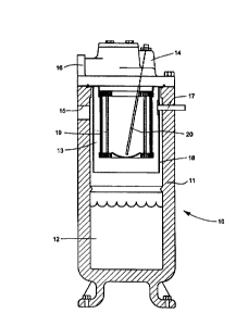
4 Referring more particularly to the drawings and initially to FIG. 1, there
is
shown an oil tank assembly 10 for use in an air compressor. The tank assembly
6 shown and described herein is typical. but it is only one of many
arrangements which
may be used. The tank assembly 10 comprises a body 11 having a reservoir 12
s formed at the bottom for collection of the compressor fluid or oiI removed
by in the
oil separation process. The upper portion of the body 11 forms a separation
chamber
to 13. The tap of the separation chamber 13 is enclosed by a tank cover 14
which is
t t attached to the body 11 by a plurality of bolts or other suitable
fastening devices with
t2 a tank seal or gasket provided between the body and the tank cover. An air
inlet 15
13 is provided on one side ofthe body 11 for air to enter the separation
chamber 13. The
t4 air flows from the separation chamber through a passage (not shown) in the
tank
is cover 14 and through an air outlet 16 provided in the tank cover.
t6 Within the separation chamber 13 may be a pre-separation configuration,
such
t~ as a generally cylindrical shroud 18 which diverts the incoming air flow
from the air
inlet 15 and causes the air to flow down and around the shroud. This provides
a first
t9 stage air-oil separation, in that, large droplets of oil are separated by
the abrupt
2o change in air flow and these oil droplets fall into the reservoir I2. Other
known pre-
zt separation configurations may be used in place of the shroud 18. A safety
valve I7
22 is also provided in the body 11 extending through the shroud 18. The safety
valve
23 17 is a pressure relief valve which opens in the event that air pressure
inside the
za shroud 18 increases above a predetermined level. The air flow then passes
upwardly
CA 02321521 2000-08-29
WO 99/47211 PCT/US99/05744
-6-
i and axially inwardly, through an air-oil separator i9. The separator 19
typically
2 comprises two or more coaxially arranged layers. including an upstream
coalescing
3 stage layer and a downstream drain stage layer. each comprised of any
suitable
combination of materials used in air-oil separation, such as fiberglass,
polyester,
s polypropylene or metal, some of which may be pleated in a conventional
manner,
6 or which may be molded, formed, wrapped or otherwise shaped. The air-oil
separator 19 also preferably includes an outer wrap layer on the exterior of
the
8 separator. and a support member along the interior surface. Each end of the
layers
are set in a hardenable sealing or potting material. such as urethane. epoxy
or
to plastisol. to make generally circular end caps. usually with metal backing,
in
~ 1 accordance with conventional air-oil separator design.
i2 A scavenging tube 20 extends downwardiy from the tank cover 14 into the
t3 separation chamber inside the separator 19. Oil draining from the separator
19 can
i4 be withdrawn therefrom using the scavenging tube 20.
is The compressor fluid or oil which is stored in the reservoir 12 and used in
the
ib air compressor is a liquid which may consist primarily of polyalphaolefin
(PAO), a
m substance which is dielectric. that is, nonconductive or insulative. and
which was
developed for use in cooling electrical power transformers. As used herein.
the terms
i9 "conductive," ''static dissipative" and "insulative" have generally the
same meaning
2o as defined by the Electrostatic Discharge Association (ESD Association) of
Rome.
z t New York. A material or substance which is considered to be ''conductive"
has a
22 conductivity of less than 10' ohms per square unit of surface area. A
material or
23 substance which is considered to be ''static dissipative" has a
conductivity of L0' to
z4 10'' ohms per square unit of surface area. A material or substance which is
zs considered to be "insulative" has a conductivity of greater than 10''- ohms
per square
26 unit of surface area. Compressor fluids such as those which are PAO-based
fluids
2~ fall within this "insuiative" range. Therefore.. the small droplets or mist
of the
CA 02321521 2000-08-29
WO 99/47211 PCT/U599105744
t compressor fluid or ail suspended in the compressor air stream is prone to
the build-
2 up of a static charge. The insulative properties of the oil keep this static
charge from
3 dissipating. As the air is acted upon by the compressor, the static charge
builds up
4 along with the temperature of the air, and the air stream becomes highly
combustible.
s In accordance with the present invention, this compressor fluid or oil is
treated
6 with a liquid which is an electrically static dissipative compound, or anti-
static agent.
bringing the compressor fluid, including the fluid suspended in the air
stream. from
s the "insulative" range to the "static dissipative'" range, and dissipating
static
electricity charges which might otherwise build-up. An example of such a
compound
to is a product sold under the trademark Staticide and available from ACL
Incorporated
t t of Elk Grove, Illinois. This product is an anti-static polymeric
composition. Other
t2 suitable static dissipative compounds or anti-static agents may be used.
The treatment of the oil may be accomplished in several different ways.
t4 During its manufacture or thereafter, one or more of the layers of the air-
oil
is separator 19 may be coated or impregnated with the electrically static
dissipative
tb compound. If a sufficient amount of the static dissipative compound is
impregnated
m into the separator 19, it will slowly leach out into the fluid. Since the
separator 19 is
tg changed at regular intervals in most compressor systems. each new separator
will
tg bring a new supply ofthe static dissipative compound which will continue to
treat the
2o compressor fluid. The separator would thus act as a dispenser, dispensing
an
2t electrically dissipative compound into the compressor fluid over a period
of time to
22 constantly treat the compressor fluid and make the fluid more electrically
dissipative.
23 By the time that the compound has fully leached from the separator, the
separator
2a would be ready for replacement, so that a new supply of the compound would
be
2s available to leach into the compressor fluid supply.
26 Coating or impregnation ofthe static dissipative compound may also make the
air/oil separator itself more electrically dissipative. Thus, any remaining
static
2s charges which may build up on the treated oil droplets will be dissipated
when the oil
CA 02321521 2000-08-29
WO 99147211 PCT/US99/05744
_g_
i encounters the electrically conductive separator 19. In order to take
advantage of this
2 effect. the separator itself must be electrically conductively mounted in
the tank
3 assembly. In other words. the separator must be grounded. It has been known
to
4 electrically ground air-oil separators by providing metal staples in the
rubber gaskets.
However, this process may adversely effect the effectiveness of the gaskets.
It is
preferred to coat the rubber seal or urethane potting compound which is used
to hold
the ends of the separator layers with the static dissipative material. In this
manner.
s the entire separator 19 may be grounded to the body of the tank assembly.
which is
itself grounded. The static dissipative material could be coated onto the
gasket or
io urethane potting layer. or it could be mixed with the urethane prior to the
curing of
i 1 the urethane, making the urethane static dissipative, by reducing the
resistance of the
~2 urethane to, for example. 10' to 109 ohms.
t3 Instead ofthe air-oil separator, the oil filter can also be used as a
dispenser for
i4 the electrically static dissipative material. An example of an oil filter
used in an air
is compressor is shown in the oil filter 21 of FIG. 2. The oil filter 21 is a
spin-on filter
ib having a rugged external casing 22 and an internal thread 23 at one end
separating
o two concentric channels 24 and 25 used for the oil inlet and outlet. The
filter 21 is
is mounted by its threaded connection 23 to the oil supply on or near the
reservoir 12.
i9 Inside the casing 22 is one or more layers of filter media 26, each
comprised of any
2o suitable combination of materials used in oil filtering, such as
fiberglass, polyester,
21 polypropylene or metal, some of which may be pleated in a conventional
manner,
22 or which may be molded, formed, wrapped or otherwise shaped. One or more
these
23 layers may be coated or impregnated with the static dissipative compound.
If a
24 sufficient amount of the static dissipative compound is impregnated into
the oil filter
25 21. it will slowly leach out into the oil. Since the oil filter 21, like
the separator 19,
26 is changed at regular intervals in most compressor systems. each new
separator will
2~ bring a new supply of the static dissipative compound which will continue
to treat the
CA 02321521 2000-08-29
WO 99147211 PCT/US99/05744
-9-
1 oiI. The oil filter would thus also act as a dispenser for the electrically
dissipative
2 compound. By the time that the compound has fully leached from the oil
filter, the
3 filter would be ready for replacement, so that a new supply of the compound
would
4 be available to leach into the oil supply.
s In addition to treating existing fluid, either by adding the electrically
dissipative compound to the fluid directly or though leaching from the air-oil
7 separator, the compressor fluid may be treated with the additive initially
during its
s manufacture, so that the amount of anti-static additive will not be
dependent upon the
amount of material added to the fluid in use. Treating the compressor fluid
initially
io may be preferred in new systems or when the compressor fluid is completely
replaced
in an existing system.
~2 The result of adding the electrically static dissipative compound or anti-
static
~3 agent to compressor fluid is to increase significantly the electrical
conductivity ofthe
is fluid. Tests have been conducted using a commonly used commercial PAO-based
is compressor fluid, and adding various levels of a static dissipative agent
to the fluid.
i6 The electrical conductivity of the fluid was then measured using the
standard test
n method ASTM D 4308, which applies to the determination of the electrical
is conductivity ofaviation fuels and other similar low-conductivity
hydrocarbon liquids
i9 in the range of 0.1 to 2000 picosiemens per meter (pS/m). Picosiemens per
meter
20 (pS/m) is the common unit of electric conductivity, with a siemen being the
reciprocal
2 i of an ohm.
1 pS/m = 1 X 10-~'- S2-~ m -~
22 Various concentrations of three different static dissipative additives, one
of which
23 was Staticide, were added to the commonly used commercially available PAO-
based
2a compressor fluid, and the conductivity of the fluid was measured according
to the
2s ASTM D 4308 test standard. The results of these tests, with the
concentration of the
CA 02321521 2000-08-29
WO 99/47211 PCT/US99/05744
-10-
1 static dissipative agents shown in parts per million (ppm), are shown in the
following
2 table and in FIG. 4.
Fluid
ConcentrationConductivity
(pS/m)
of Additive AdditiveAdditiveAdditive
s (ppm) A B C
10 6 83 17
100 12 33I 53
X00 25 862 96
1.000 49 1997 121
The test results show that the typical PAO-based compressor fluid by itself is
t t insulative, having very low measurements of conductivity. The addition of
an static
~2 dissipative agent, such as Staticide, significantly increases the
conductivity of the
t3 compressor fluid. The addition of relative small amounts of the additive
can change
14 the compressor fluid from "insulative" to "static dissipative" as defined
above. The
is increased conductivity of the compressor fluid with the added static
dissipative
16 additive can be compared to the desired electrical conductivity for
aviation turbine
m fuels which should be 50 to 450 pS/m to prevent static charge flammability
problems
is in fuel tanks. By raising the conductivity of the fluid to 1 pS/m, the
fluid becomes
19 "static dissipative." Preferably, the conductivity of the fluid is raised
to 50 pS/m or
2o higher by the addition of the additive in order for the fluid to have
sufficient static
2i dissipative properties that dangerous levels of static charge build-up are
avoided. It
22 can be seen that such levels of electrical conductivity can be achieved
with the
23 addition of small levels of an anti-static agent to compressor fluids.
24 Other variations and modifications of the specific embodiments herein shown
2s and described will be apparent to those skilled in the art, all within the
intended spirit
26 and scope of the invention. While the invention has been shown and
described with
CA 02321521 2000-08-29
w0 99147211 PC'T1US99/05744
-11-
i respect to particular embodiments thereof, these are for the purpose of
illustration
2 rather than limitation. Accordingly, the patent is not to be limited in
scope and effect
to the specific embodiments herein shown and described nor in any other way
that is
inconsistent with the extent to which the progress in the art has been
advanced by the
s invention.