Language selection

Search

Patent 2321822 Summary

Third-party information liability

Some of the information on this Web page has been provided by external sources. The Government of Canada is not responsible for the accuracy, reliability or currency of the information supplied by external sources. Users wishing to rely upon this information should consult directly with the source of the information. Content provided by external sources is not subject to official languages, privacy and accessibility requirements.

Claims and Abstract availability

Any discrepancies in the text and image of the Claims and Abstract are due to differing posting times. Text of the Claims and Abstract are posted:

  • At the time the application is open to public inspection;
  • At the time of issue of the patent (grant).
(12) Patent Application: (11) CA 2321822
(54) English Title: CONNECTING DEVICE
(54) French Title: DISPOSITIF DE CONNEXION
Status: Deemed Abandoned and Beyond the Period of Reinstatement - Pending Response to Notice of Disregarded Communication
Bibliographic Data
(51) International Patent Classification (IPC):
  • F16L 03/04 (2006.01)
  • E04D 13/08 (2006.01)
  • F16L 03/00 (2006.01)
  • F16L 03/10 (2006.01)
(72) Inventors :
  • RICHARDSON, CHRISTOPHER (United Kingdom)
(73) Owners :
  • ULTRAFRAME (UK) LIMITED
(71) Applicants :
  • ULTRAFRAME (UK) LIMITED (United Kingdom)
(74) Agent: MARKS & CLERK
(74) Associate agent:
(45) Issued:
(86) PCT Filing Date: 1999-01-26
(87) Open to Public Inspection: 1999-09-30
Availability of licence: N/A
Dedicated to the Public: N/A
(25) Language of filing: English

Patent Cooperation Treaty (PCT): Yes
(86) PCT Filing Number: PCT/GB1999/000262
(87) International Publication Number: GB1999000262
(85) National Entry: 2000-08-23

(30) Application Priority Data:
Application No. Country/Territory Date
9806428.0 (United Kingdom) 1998-03-26

Abstracts

English Abstract


A connecting device (10) for securing a down pipe to a wall comprises a first
part (12) fixable to the surface and a second part (14) attachable to the
first part and forming an at least partial enclosure for the pipe the
attachment of the second part to the first part (22, 44) being selectively
adjustable, whereby spacing of the pipe from the surface is adjustable.


French Abstract

L'invention se rapporte à un dispositif de connexion (10) conçu pour fixer un tuyau de descente des eaux pluviales sur un mur et comportant une première partie (12) qu'il est possible de fixer à la surface et une seconde partie (14) qu'il est possible d'attacher à la première partie et qui constitue une enveloppe au moins partielle pour le tuyau. La fixation de la seconde partie à la première partie (22, 44) peut être réglée de manière sélective, ce qui permet d'ajuster l'espacement du tuyau par rapport à la surface.

Claims

Note: Claims are shown in the official language in which they were submitted.

6
CLAIMS
1. A connecting device suitable for attaching a pipe to a surface comprising a
first part fixable to the surface and a second part slidably attachable to the
first part
in the direction of the pipe to a limited extent and forming an at least
partial
enclosure for the pipe, the first and second parts having co-operating
formations
enabling the attachment of the second part to the first part to be selectably
adjustable, whereby spacing of the pipe from the surface is adjustable.
2. A device as claimed in claim 1, wherein the first part is U-shaped
providing
a base, which is arranged to be fixed to the surface, and arms extending from
the
base.
3. A device as claimed in claims 1 or 2, wherein the second part is U-shaped
having a base and an arm extending from each end of the base.
4. A device as claimed in claim 3, wherein the arms of the first and second
parts are selectively interengageable.
5. A device as claimed in claim 4, wherein inner faces of the arm of one part
have a series of spaced teeth which are selectively engageable between
corresponding teeth on outer faces of the arms of the other part.
6. A device as claimed in claim 5, wherein the teeth of the outer faces of the
arms of the other part are within channels in the arms.
7. A device as claimed in claim 5 or 6, wherein the respective series of teeth
are arranged so that the two parts of the device are only engageable to a
limited
extent, whereby one part is prevented from slipping past the other part.

7
8. A device as claimed in claim 7, wherein abutments are provided on each
arm for the teeth of an arm of the other part.
9. A device as claimed in claim 8, wherein the abutments are provided by
base strips from which the teeth of each arm extend.
10. A device as claimed in claim 7, wherein the respective series of teeth are
shaped to limit their extent of movement together.
11. A device as claimed in claim 10, wherein the teeth are triangular in plan.
12. A device as claimed in any one of claims 1 to 10, wherein the second part
has inwards returns at the ends of its arms.

Description

Note: Descriptions are shown in the official language in which they were submitted.


:.:ii: ..
:::i<:::r:::::??:4:::::::'::
;:
::i:
:
:
:
: :
:
::~~r~y:':: "-
CA 0 2 3 218 22..-2 0 0 0 - 0 8 - 2 3::: ~:
~
:
:::x.~,rtsv.>::.x:
. >.:,:x.,
, :. ":. ....:.
,; .:_.;' [..:;: ::=:~ . . ..~. . , : .~ ., . i~.s::.r.:
::
::::::::::::~::;: :: n ~ ~
~~.a;;
.............:.......::: ,.. .~.E:~.:.:~:~:~1~ v. . . . :
: .~ : ' :. " ....:
:.,.:.... ~
. . ..~.!! .
: ' . . ..
... ...................... n:::::
~'.:.....
.
i
bW
'
~
r '
.7 . .::.~?k
7 N:.
Y '.v.i.?:
M~:..:.:_r.
ss.. ....
.s ~
s::bl.,.~::::. .
.
.
, ..u.:..: ...:.n:.
~ ~ ~ ~ ~ ~ ~ ~ ~ ~ ..
~ ~ .
,',
...
,
.,
,
a:<,'sx.',k.:R:'..rt:..s:f~s:.:..>.
TITLE: Connecting Device
DESCRIPTION
This invention concerns connecting devices, especially connecting devices
for attaching pipes or other elongate items to underlying surfaces, such as to
walls.
A down pipe for delivering water collected in a gutter to a drain is usually
attached to a wall using clips that are secured to the wall and fastened
around the
down pipe. Available clips are of one size and so do not allow for variations
in
spacing between the down pipe and the wall which occur due to irregularities
in the
wall and the relative positioning of the guttering to which the down pipe is
connected at its top. Because of the above, sometimes clips cannot be fastened
property and so spring open or strain is put on the down pipe affecting its
connection to the guttering or its other fastening clips.
An object of this invention is to provide a connecting device especially but
not exclusively suitable for attaching a pipe to a surface.
A connecting device suitable for attaching a pipe to a surface comprising a
first part fixable to the surface and a second part slidably attachable to the
first part
in the direction of the pipe to a limited extent and forming an at least
partial
enclosure for the pipe, the first and second parts having co-operating
formations
enabling the attachment of the second part to the first part to be selectably
adjustable, whereby spacing of the pipe from the surface is adjustable.
::_;:<:<::::::.,_>.;_:,~~~.~:::.?_::.~.:.:.>:A _
:, IVIENDfD SH~E~ .<::::~.
................... ...:::::::::::::. ::: .
;:::

CA 02321822 2000-08-23
WO 99/49253 PCT/GB99/00262
2
The first part of the connecting device of the invention is preferably U-
shaped providing a base which is arranged to be fixed to the surface, such as,
for
example, by means of one or more screws or the like through provided holes in
the
base, and arms extending from the base.
The second part of the connecting device of the invention is preferably also
U-shaped having a base and an arm extending from each end of the base. The
arms of the first and second parts of the connecting device of the invention
are
preferably selectively interengageable. The inner faces of the arms of one
part
preferably have a series of spaced teeth which are selectively engageable
between corresponding teeth on outer faces of the arms of the other connecting
device part.
The teeth of the outer faces of the arms of the other connecting device part,
preferably the second part are preferably within channels in the arms, so that
the
arms of one part fit into the corresponding channels of the arms of the other
part
when the respective series of teeth are interengaged.
The respective series of teeth are preferably arranged so that the two parts
of the connecting device of the invention can only be engaged to a limited
extent in
order to prevent them from slipping past each other. Thus, abutments may be
provided on each arm for the teeth of an arm of the other part of the device
with
which it is to engage. The abutments may be provided by base strips from which
the teeth of each arm extend. Alternatively, the teeth may be shaped, such as
by
being triangular in plan, whereby their extent of movement together is limited
by
said shaping.

CA 02321822 2000-08-23
WO 99/49253 PCT/GB99/00262
3
The second part of the connecting device of the invention preferably has
inwards returns at the ends of its arms, so that a pipe or the like is
retained in said
second part.
The connector device of the invention is preferably used by fixing the first
part to a surface and sliding the second part onto a pipe and down onto the
first
part to engage the two parts and hold the pipe to the surface. The second part
will
engage the first part at a desired spacing from the pipe from the surface.
This invention will now be further described, by way of example only, with
reference to the accompanying drawings, in which:
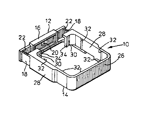
Figure 1 is a perspective view from above of a down pipe connecting device
according to the invention;
Figure 2 is a perspective view from below of the connecting device of Figure
1;
Figure 3 is a part cut away perspective view from above of the connecting
device of Figure 1;
Figure 4 is a perspective view from below of the connecting device of Figure
1 fitted to a down pipe;
Figure 5 is a perspective from above of the connecting device of Figure 1
fitted to a down pipe;
Figure 6A to D shows steps in fitting a connecting device of Figure 1 to a
down pipe.
Refer-ing to the accompanying drawings, a connecting device or clip 10 for
securing a down pipe 11 to a wall or other surface, such as a mullion or comer

CA 02321822 2000-08-23
WO 99/49253 PCT/GB99/00262
4
post of a glazed conservatory wall, comprises two parts 12 and 14. The two
parts
12, 14 are generally U-shaped and shaped to fit together in an overlapping
fashion.
The one part 12 has a base 16 and sides 18 extending generally normally
from the base. The base 1 fi is provided with a screw hole 20 so that it can
be
secured to a wall or other suitable surface. The sides 18 have on their facing
surfaces spaced teeth 22 extending upwards from a base strip 24.
The other part 14 of the clip has a base 26 and sides 28 that tum inwards at
their ends 30 to a small extent. The part 14 has its internal corners rounded
to
correspond to the shape of conventional square section down pipes. Of course,
the part 14 of the clip may be of any desired shape, such as to fit circular
section
pipes. On their internal surfaces, the base 26 and sides 28 and each have a
pair
of spaced ribs 32.~ The ends 30 of the sides 28 each also have on their
internal
surface at the end thereof a rib 34. The ribs 32 and 34 simply facilitate the
fitting of
the clip to a downpipe by reducing areas of contact and hence reducing
friction
between the clip and the down pipe.
The sides 28 of the second clip part 14 are wider over a major portion of
their length up to their free ends and the wider portions are slotted from
below to
form channels 42. On the inside of each channel 42 on one face thereof from a
base strip 43 extend a series of spaced teeth 44 shaped and sized to interfit
between the teeth 22 of the sides 18 of the one part 12. Thus, the second part
14
can be slid down onto the first part 12 with the teeth of the one part engaged
with
the teeth of the other part at a desired position to give a desired spacing of
the

CA 02321822 2000-08-23
WO 99/49253 PCTlGB99/00262
S
second part from the base 16 of the first part. The respective base strips 24
and
43 limit the extent of interengagement of the teeth.
The clip 10 is used in the following manner as shown in Figures 6A to 6D of
the accompanying drawings to fix a down pipe to a wail or other suitable
surface.
Firstly the first part 12 is fixed to the wall or other suitable surface at a
desired
location using a screw through the base 16. Then the second part is placed on
the
down pipe and the down pipe positioned, which may involve coupling thereof to
a
gutter. The second part of the clip is then slid down onto the first part so
that their
respective teeth interengage. The two parts of the clip may lock together
simply by
friction, by mechanical fixings or by engagement of integral locking
components.
It will be appreciated that whilst the connecting device of the invention has
been described in relation to connecting down pipes to a structure, the
connecting
device of the invention may be used for connecting other elongate items to an
underlying structure in any orientation.

Representative Drawing
A single figure which represents the drawing illustrating the invention.
Administrative Status

2024-08-01:As part of the Next Generation Patents (NGP) transition, the Canadian Patents Database (CPD) now contains a more detailed Event History, which replicates the Event Log of our new back-office solution.

Please note that "Inactive:" events refers to events no longer in use in our new back-office solution.

For a clearer understanding of the status of the application/patent presented on this page, the site Disclaimer , as well as the definitions for Patent , Event History , Maintenance Fee  and Payment History  should be consulted.

Event History

Description Date
Inactive: IPC from MCD 2006-03-12
Application Not Reinstated by Deadline 2005-01-26
Time Limit for Reversal Expired 2005-01-26
Deemed Abandoned - Failure to Respond to Maintenance Fee Notice 2004-01-26
Inactive: Abandon-RFE+Late fee unpaid-Correspondence sent 2004-01-26
Inactive: Cover page published 2000-12-14
Inactive: First IPC assigned 2000-11-22
Inactive: Notice - National entry - No RFE 2000-11-08
Letter Sent 2000-11-06
Application Received - PCT 2000-11-04
Application Published (Open to Public Inspection) 1999-09-30

Abandonment History

Abandonment Date Reason Reinstatement Date
2004-01-26

Maintenance Fee

The last payment was received on 2002-12-27

Note : If the full payment has not been received on or before the date indicated, a further fee may be required which may be one of the following

  • the reinstatement fee;
  • the late payment fee; or
  • additional fee to reverse deemed expiry.

Patent fees are adjusted on the 1st of January every year. The amounts above are the current amounts if received by December 31 of the current year.
Please refer to the CIPO Patent Fees web page to see all current fee amounts.

Fee History

Fee Type Anniversary Year Due Date Paid Date
Basic national fee - standard 2000-08-23
MF (application, 2nd anniv.) - standard 02 2001-01-26 2000-08-23
Registration of a document 2000-08-23
MF (application, 3rd anniv.) - standard 03 2002-01-28 2001-12-21
MF (application, 4th anniv.) - standard 04 2003-01-27 2002-12-27
Owners on Record

Note: Records showing the ownership history in alphabetical order.

Current Owners on Record
ULTRAFRAME (UK) LIMITED
Past Owners on Record
CHRISTOPHER RICHARDSON
Past Owners that do not appear in the "Owners on Record" listing will appear in other documentation within the application.
Documents

To view selected files, please enter reCAPTCHA code :


To view images, click a link in the Document Description column. To download the documents, select one or more checkboxes in the first column and then click the "Download Selected in PDF format (Zip Archive)" or the "Download Selected as Single PDF" button.

List of published and non-published patent-specific documents on the CPD .

If you have any difficulty accessing content, you can call the Client Service Centre at 1-866-997-1936 or send them an e-mail at CIPO Client Service Centre.


Document
Description 
Date
(yyyy-mm-dd) 
Number of pages   Size of Image (KB) 
Representative drawing 2000-12-07 1 13
Claims 2000-08-22 2 66
Drawings 2000-08-22 5 145
Description 2000-08-22 5 199
Abstract 2000-08-22 1 55
Notice of National Entry 2000-11-07 1 195
Courtesy - Certificate of registration (related document(s)) 2000-11-05 1 113
Reminder - Request for Examination 2003-09-28 1 112
Courtesy - Abandonment Letter (Request for Examination) 2004-04-04 1 167
Courtesy - Abandonment Letter (Maintenance Fee) 2004-03-21 1 175
PCT 2000-08-22 11 358