Sélection de la langue

Search

Sommaire du brevet 2321822 

Énoncé de désistement de responsabilité concernant l'information provenant de tiers

Une partie des informations de ce site Web a été fournie par des sources externes. Le gouvernement du Canada n'assume aucune responsabilité concernant la précision, l'actualité ou la fiabilité des informations fournies par les sources externes. Les utilisateurs qui désirent employer cette information devraient consulter directement la source des informations. Le contenu fourni par les sources externes n'est pas assujetti aux exigences sur les langues officielles, la protection des renseignements personnels et l'accessibilité.

Disponibilité de l'Abrégé et des Revendications

L'apparition de différences dans le texte et l'image des Revendications et de l'Abrégé dépend du moment auquel le document est publié. Les textes des Revendications et de l'Abrégé sont affichés :

  • lorsque la demande peut être examinée par le public;
  • lorsque le brevet est émis (délivrance).
(12) Demande de brevet: (11) CA 2321822
(54) Titre français: DISPOSITIF DE CONNEXION
(54) Titre anglais: CONNECTING DEVICE
Statut: Réputée abandonnée et au-delà du délai pour le rétablissement - en attente de la réponse à l’avis de communication rejetée
Données bibliographiques
(51) Classification internationale des brevets (CIB):
  • F16L 03/04 (2006.01)
  • E04D 13/08 (2006.01)
  • F16L 03/00 (2006.01)
  • F16L 03/10 (2006.01)
(72) Inventeurs :
  • RICHARDSON, CHRISTOPHER (Royaume-Uni)
(73) Titulaires :
  • ULTRAFRAME (UK) LIMITED
(71) Demandeurs :
  • ULTRAFRAME (UK) LIMITED (Royaume-Uni)
(74) Agent: MARKS & CLERK
(74) Co-agent:
(45) Délivré:
(86) Date de dépôt PCT: 1999-01-26
(87) Mise à la disponibilité du public: 1999-09-30
Licence disponible: S.O.
Cédé au domaine public: S.O.
(25) Langue des documents déposés: Anglais

Traité de coopération en matière de brevets (PCT): Oui
(86) Numéro de la demande PCT: PCT/GB1999/000262
(87) Numéro de publication internationale PCT: GB1999000262
(85) Entrée nationale: 2000-08-23

(30) Données de priorité de la demande:
Numéro de la demande Pays / territoire Date
9806428.0 (Royaume-Uni) 1998-03-26

Abrégés

Abrégé français

L'invention se rapporte à un dispositif de connexion (10) conçu pour fixer un tuyau de descente des eaux pluviales sur un mur et comportant une première partie (12) qu'il est possible de fixer à la surface et une seconde partie (14) qu'il est possible d'attacher à la première partie et qui constitue une enveloppe au moins partielle pour le tuyau. La fixation de la seconde partie à la première partie (22, 44) peut être réglée de manière sélective, ce qui permet d'ajuster l'espacement du tuyau par rapport à la surface.


Abrégé anglais


A connecting device (10) for securing a down pipe to a wall comprises a first
part (12) fixable to the surface and a second part (14) attachable to the
first part and forming an at least partial enclosure for the pipe the
attachment of the second part to the first part (22, 44) being selectively
adjustable, whereby spacing of the pipe from the surface is adjustable.

Revendications

Note : Les revendications sont présentées dans la langue officielle dans laquelle elles ont été soumises.


6
CLAIMS
1. A connecting device suitable for attaching a pipe to a surface comprising a
first part fixable to the surface and a second part slidably attachable to the
first part
in the direction of the pipe to a limited extent and forming an at least
partial
enclosure for the pipe, the first and second parts having co-operating
formations
enabling the attachment of the second part to the first part to be selectably
adjustable, whereby spacing of the pipe from the surface is adjustable.
2. A device as claimed in claim 1, wherein the first part is U-shaped
providing
a base, which is arranged to be fixed to the surface, and arms extending from
the
base.
3. A device as claimed in claims 1 or 2, wherein the second part is U-shaped
having a base and an arm extending from each end of the base.
4. A device as claimed in claim 3, wherein the arms of the first and second
parts are selectively interengageable.
5. A device as claimed in claim 4, wherein inner faces of the arm of one part
have a series of spaced teeth which are selectively engageable between
corresponding teeth on outer faces of the arms of the other part.
6. A device as claimed in claim 5, wherein the teeth of the outer faces of the
arms of the other part are within channels in the arms.
7. A device as claimed in claim 5 or 6, wherein the respective series of teeth
are arranged so that the two parts of the device are only engageable to a
limited
extent, whereby one part is prevented from slipping past the other part.

7
8. A device as claimed in claim 7, wherein abutments are provided on each
arm for the teeth of an arm of the other part.
9. A device as claimed in claim 8, wherein the abutments are provided by
base strips from which the teeth of each arm extend.
10. A device as claimed in claim 7, wherein the respective series of teeth are
shaped to limit their extent of movement together.
11. A device as claimed in claim 10, wherein the teeth are triangular in plan.
12. A device as claimed in any one of claims 1 to 10, wherein the second part
has inwards returns at the ends of its arms.

Description

Note : Les descriptions sont présentées dans la langue officielle dans laquelle elles ont été soumises.

:.:ii: ..
:::i<:::r:::::??:4:::::::'::
;:
::i:
:
:
:
: :
:
::~~r~y:':: "-
CA 0 2 3 218 22..-2 0 0 0 - 0 8 - 2 3::: ~:
~
:
:::x.~,rtsv.>::.x:
. >.:,:x.,
, :. ":. ....:.
,; .:_.;' [..:;: ::=:~ . . ..~. . , : .~ ., . i~.s::.r.:
::
::::::::::::~::;: :: n ~ ~
~~.a;;
.............:.......::: ,.. .~.E:~.:.:~:~:~1~ v. . . . :
: .~ : ' :. " ....:
:.,.:.... ~
. . ..~.!! .
: ' . . ..
... ...................... n:::::
~'.:.....
.
i
bW
'
~
r '
.7 . .::.~?k
7 N:.
Y '.v.i.?:
M~:..:.:_r.
ss.. ....
.s ~
s::bl.,.~::::. .
.
.
, ..u.:..: ...:.n:.
~ ~ ~ ~ ~ ~ ~ ~ ~ ~ ..
~ ~ .
,',
...
,
.,
,
a:<,'sx.',k.:R:'..rt:..s:f~s:.:..>.
TITLE: Connecting Device
DESCRIPTION
This invention concerns connecting devices, especially connecting devices
for attaching pipes or other elongate items to underlying surfaces, such as to
walls.
A down pipe for delivering water collected in a gutter to a drain is usually
attached to a wall using clips that are secured to the wall and fastened
around the
down pipe. Available clips are of one size and so do not allow for variations
in
spacing between the down pipe and the wall which occur due to irregularities
in the
wall and the relative positioning of the guttering to which the down pipe is
connected at its top. Because of the above, sometimes clips cannot be fastened
property and so spring open or strain is put on the down pipe affecting its
connection to the guttering or its other fastening clips.
An object of this invention is to provide a connecting device especially but
not exclusively suitable for attaching a pipe to a surface.
A connecting device suitable for attaching a pipe to a surface comprising a
first part fixable to the surface and a second part slidably attachable to the
first part
in the direction of the pipe to a limited extent and forming an at least
partial
enclosure for the pipe, the first and second parts having co-operating
formations
enabling the attachment of the second part to the first part to be selectably
adjustable, whereby spacing of the pipe from the surface is adjustable.
::_;:<:<::::::.,_>.;_:,~~~.~:::.?_::.~.:.:.>:A _
:, IVIENDfD SH~E~ .<::::~.
................... ...:::::::::::::. ::: .
;:::

CA 02321822 2000-08-23
WO 99/49253 PCT/GB99/00262
2
The first part of the connecting device of the invention is preferably U-
shaped providing a base which is arranged to be fixed to the surface, such as,
for
example, by means of one or more screws or the like through provided holes in
the
base, and arms extending from the base.
The second part of the connecting device of the invention is preferably also
U-shaped having a base and an arm extending from each end of the base. The
arms of the first and second parts of the connecting device of the invention
are
preferably selectively interengageable. The inner faces of the arms of one
part
preferably have a series of spaced teeth which are selectively engageable
between corresponding teeth on outer faces of the arms of the other connecting
device part.
The teeth of the outer faces of the arms of the other connecting device part,
preferably the second part are preferably within channels in the arms, so that
the
arms of one part fit into the corresponding channels of the arms of the other
part
when the respective series of teeth are interengaged.
The respective series of teeth are preferably arranged so that the two parts
of the connecting device of the invention can only be engaged to a limited
extent in
order to prevent them from slipping past each other. Thus, abutments may be
provided on each arm for the teeth of an arm of the other part of the device
with
which it is to engage. The abutments may be provided by base strips from which
the teeth of each arm extend. Alternatively, the teeth may be shaped, such as
by
being triangular in plan, whereby their extent of movement together is limited
by
said shaping.

CA 02321822 2000-08-23
WO 99/49253 PCT/GB99/00262
3
The second part of the connecting device of the invention preferably has
inwards returns at the ends of its arms, so that a pipe or the like is
retained in said
second part.
The connector device of the invention is preferably used by fixing the first
part to a surface and sliding the second part onto a pipe and down onto the
first
part to engage the two parts and hold the pipe to the surface. The second part
will
engage the first part at a desired spacing from the pipe from the surface.
This invention will now be further described, by way of example only, with
reference to the accompanying drawings, in which:
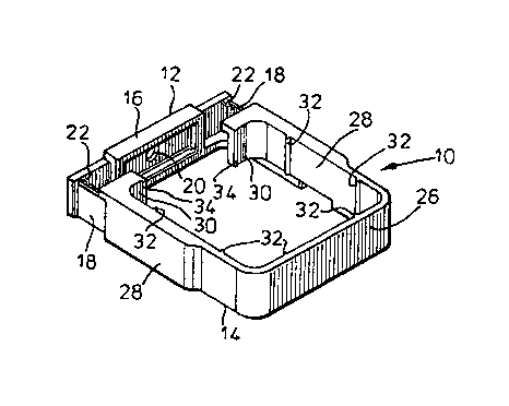
Figure 1 is a perspective view from above of a down pipe connecting device
according to the invention;
Figure 2 is a perspective view from below of the connecting device of Figure
1;
Figure 3 is a part cut away perspective view from above of the connecting
device of Figure 1;
Figure 4 is a perspective view from below of the connecting device of Figure
1 fitted to a down pipe;
Figure 5 is a perspective from above of the connecting device of Figure 1
fitted to a down pipe;
Figure 6A to D shows steps in fitting a connecting device of Figure 1 to a
down pipe.
Refer-ing to the accompanying drawings, a connecting device or clip 10 for
securing a down pipe 11 to a wall or other surface, such as a mullion or comer

CA 02321822 2000-08-23
WO 99/49253 PCT/GB99/00262
4
post of a glazed conservatory wall, comprises two parts 12 and 14. The two
parts
12, 14 are generally U-shaped and shaped to fit together in an overlapping
fashion.
The one part 12 has a base 16 and sides 18 extending generally normally
from the base. The base 1 fi is provided with a screw hole 20 so that it can
be
secured to a wall or other suitable surface. The sides 18 have on their facing
surfaces spaced teeth 22 extending upwards from a base strip 24.
The other part 14 of the clip has a base 26 and sides 28 that tum inwards at
their ends 30 to a small extent. The part 14 has its internal corners rounded
to
correspond to the shape of conventional square section down pipes. Of course,
the part 14 of the clip may be of any desired shape, such as to fit circular
section
pipes. On their internal surfaces, the base 26 and sides 28 and each have a
pair
of spaced ribs 32.~ The ends 30 of the sides 28 each also have on their
internal
surface at the end thereof a rib 34. The ribs 32 and 34 simply facilitate the
fitting of
the clip to a downpipe by reducing areas of contact and hence reducing
friction
between the clip and the down pipe.
The sides 28 of the second clip part 14 are wider over a major portion of
their length up to their free ends and the wider portions are slotted from
below to
form channels 42. On the inside of each channel 42 on one face thereof from a
base strip 43 extend a series of spaced teeth 44 shaped and sized to interfit
between the teeth 22 of the sides 18 of the one part 12. Thus, the second part
14
can be slid down onto the first part 12 with the teeth of the one part engaged
with
the teeth of the other part at a desired position to give a desired spacing of
the

CA 02321822 2000-08-23
WO 99/49253 PCTlGB99/00262
S
second part from the base 16 of the first part. The respective base strips 24
and
43 limit the extent of interengagement of the teeth.
The clip 10 is used in the following manner as shown in Figures 6A to 6D of
the accompanying drawings to fix a down pipe to a wail or other suitable
surface.
Firstly the first part 12 is fixed to the wall or other suitable surface at a
desired
location using a screw through the base 16. Then the second part is placed on
the
down pipe and the down pipe positioned, which may involve coupling thereof to
a
gutter. The second part of the clip is then slid down onto the first part so
that their
respective teeth interengage. The two parts of the clip may lock together
simply by
friction, by mechanical fixings or by engagement of integral locking
components.
It will be appreciated that whilst the connecting device of the invention has
been described in relation to connecting down pipes to a structure, the
connecting
device of the invention may be used for connecting other elongate items to an
underlying structure in any orientation.

Dessin représentatif
Une figure unique qui représente un dessin illustrant l'invention.
États administratifs

2024-08-01 : Dans le cadre de la transition vers les Brevets de nouvelle génération (BNG), la base de données sur les brevets canadiens (BDBC) contient désormais un Historique d'événement plus détaillé, qui reproduit le Journal des événements de notre nouvelle solution interne.

Veuillez noter que les événements débutant par « Inactive : » se réfèrent à des événements qui ne sont plus utilisés dans notre nouvelle solution interne.

Pour une meilleure compréhension de l'état de la demande ou brevet qui figure sur cette page, la rubrique Mise en garde , et les descriptions de Brevet , Historique d'événement , Taxes périodiques et Historique des paiements devraient être consultées.

Historique d'événement

Description Date
Inactive : CIB de MCD 2006-03-12
Demande non rétablie avant l'échéance 2005-01-26
Le délai pour l'annulation est expiré 2005-01-26
Réputée abandonnée - omission de répondre à un avis sur les taxes pour le maintien en état 2004-01-26
Inactive : Abandon.-RE+surtaxe impayées-Corr envoyée 2004-01-26
Inactive : Page couverture publiée 2000-12-14
Inactive : CIB en 1re position 2000-11-22
Inactive : Notice - Entrée phase nat. - Pas de RE 2000-11-08
Lettre envoyée 2000-11-06
Demande reçue - PCT 2000-11-04
Demande publiée (accessible au public) 1999-09-30

Historique d'abandonnement

Date d'abandonnement Raison Date de rétablissement
2004-01-26

Taxes périodiques

Le dernier paiement a été reçu le 2002-12-27

Avis : Si le paiement en totalité n'a pas été reçu au plus tard à la date indiquée, une taxe supplémentaire peut être imposée, soit une des taxes suivantes :

  • taxe de rétablissement ;
  • taxe pour paiement en souffrance ; ou
  • taxe additionnelle pour le renversement d'une péremption réputée.

Les taxes sur les brevets sont ajustées au 1er janvier de chaque année. Les montants ci-dessus sont les montants actuels s'ils sont reçus au plus tard le 31 décembre de l'année en cours.
Veuillez vous référer à la page web des taxes sur les brevets de l'OPIC pour voir tous les montants actuels des taxes.

Historique des taxes

Type de taxes Anniversaire Échéance Date payée
Taxe nationale de base - générale 2000-08-23
TM (demande, 2e anniv.) - générale 02 2001-01-26 2000-08-23
Enregistrement d'un document 2000-08-23
TM (demande, 3e anniv.) - générale 03 2002-01-28 2001-12-21
TM (demande, 4e anniv.) - générale 04 2003-01-27 2002-12-27
Titulaires au dossier

Les titulaires actuels et antérieures au dossier sont affichés en ordre alphabétique.

Titulaires actuels au dossier
ULTRAFRAME (UK) LIMITED
Titulaires antérieures au dossier
CHRISTOPHER RICHARDSON
Les propriétaires antérieurs qui ne figurent pas dans la liste des « Propriétaires au dossier » apparaîtront dans d'autres documents au dossier.
Documents

Pour visionner les fichiers sélectionnés, entrer le code reCAPTCHA :


Pour visualiser une image, cliquer sur un lien dans la colonne description du document. Pour télécharger l'image (les images), cliquer l'une ou plusieurs cases à cocher dans la première colonne et ensuite cliquer sur le bouton "Télécharger sélection en format PDF (archive Zip)" ou le bouton "Télécharger sélection (en un fichier PDF fusionné)".

Liste des documents de brevet publiés et non publiés sur la BDBC .

Si vous avez des difficultés à accéder au contenu, veuillez communiquer avec le Centre de services à la clientèle au 1-866-997-1936, ou envoyer un courriel au Centre de service à la clientèle de l'OPIC.


Description du
Document 
Date
(aaaa-mm-jj) 
Nombre de pages   Taille de l'image (Ko) 
Dessin représentatif 2000-12-07 1 13
Revendications 2000-08-22 2 66
Dessins 2000-08-22 5 145
Description 2000-08-22 5 199
Abrégé 2000-08-22 1 55
Avis d'entree dans la phase nationale 2000-11-07 1 195
Courtoisie - Certificat d'enregistrement (document(s) connexe(s)) 2000-11-05 1 113
Rappel - requête d'examen 2003-09-28 1 112
Courtoisie - Lettre d'abandon (requête d'examen) 2004-04-04 1 167
Courtoisie - Lettre d'abandon (taxe de maintien en état) 2004-03-21 1 175
PCT 2000-08-22 11 358