Note: Descriptions are shown in the official language in which they were submitted.
CA 02321857 2000-08-23
WO 99/43623 PCT/CA99/00171
WASTE TREATMENT SYSTEM
The present invention relates to a method of treating waste.
BACKGROUND OF THE INVENTION
According to municipalities, government agencies, environmentalists
and the public in general, odour and potential pollution sources emanatirig
from
swine facilities are the main issues that the hog industry needs to address in
order
to sustain its development. The most intense source of odour from livestock
facilities occurs during manure handling and land application. The manure from
hogs can generally be classified as low volume, high strength liquid waste.
That is,
waste of high strength requires high levels of oxygen to biodegrade and may
contaminate ground water. Typically, most commercial hog operations feature
under-floor manure storage pits. These pits are situated beneath the barns and
store the manure until the manure is emptied from the pit and transferred to
mid-
term storage lagoons. The odour problem that arises when the manure is stored
in
such a manner is a result of the anaerobic conditions that exist in the
lagoon.
Typically, aerobic conditions exist only in the layer of manure that is in
contact with
air and the malodorous gases produced anaerobically beneath this layer
gradually
diffuse to the surface, which in turn raises the prospect of public annoyance
and
creates health concerns for the swine herd and the barn workers. Conditions
where anaerobic processes under very low dissolved oxygen (<0.5 mg/I)
conditions occur are referred to as anoxic conditions. Current methods used in
controlling odour production during manure handling and land application have
only been capable of suppressing or delaying odour production. Without an
adequate treatment, producers are forced to handle manure that is highly non-
CA 02321857 2000-08-23
WO 99/43623 PCT/CA99/00171
2
homogeneous, which can cause a variety of technical and mechanical related
problems. Therefore, a method of waste treatment must ensure odour reduction
or
elimination as well as a reduction in solids content or volume and waste
strength.
Waste strength is directly related to the Biological Oxygen Demand (BOD) of
the
waste. The BOD defines the waste strength in that it depicts the amount of
oxygen
required by the waste in order to biodegrade. Such a method will reduce
handling
concerns and pollution such as ground water contamination and/or air pollution
caused by the malodorous gases. Furthermore, the treated waste produced should
be a low strength waste and have high nutrient content (nitrogen, phosphorus,
potassium) which is essential for fertilizer value.
It is of note that nutrient application to farm land must be balanced
with the ability of the crops to utilize the nutrients applied. That is,
excess nutrients
in the fertilizer that are not absorbed by the soil are likely to contaminate
the
aquifers and surface water bodies. As a result, the amount of fertilizer that
can be
applied to a given plot of land is highly dependent upon the local soil
conditions,
hydrology, geology and geography. However, in many cases, it is not cost
effective
for swine producers to haul raw manure long distances if the land surrounding
the
facility is already nutrient rich. Clearly, in cases such as these, it would
be
preferable to be able to separate the nutrients from the manure, thereby
producing
a concentrated fertilizer. As a result, the condensed fertilizer could be cost
effectively transported and applied to farm land significant distances away
from the
swine production facility.
CA 02321857 2000-08-23
WO 99/43623 PCT/CA99/00171
3
SUMMARY OF THE INVENTION
It is an object of the invention, therefore, to provide a system for
treating waste.
According to one aspect of the invention there is provided a method
of treating waste liquid containing solid content comprising:
providing waste liquid containing solid content;
heating the waste to a temperature range of 40-70°C for a time
period of 12-36 hours, thereby reducing waste strength and odour of the waste;
and
separating the treated waste into liquid material and solid material.
Heating will eliminate many pathogens within the waste.
Preferably, the waste is mixed and shredded during heating.
Preferably, the method includes treating the waste with augmenting
bacteria and enzymes prior to heating. The addition of bacteria and enzymes
promotes anoxic/anaerobic breakdown of the waste in the manure pit.
Preferably, the method includes removing gases emitted during
heating of the waste and bubbling the gases back into the liquid material and
the
solid material. As a result of this arrangement, the nutrient content of the
liquid
material and the solid material is enhanced.
The liquid and/or solid material may be used as fertilizer and/or
disposed of as a benign waste.
Preferably, the waste strength and the odour of the waste are
CA 02321857 2000-08-23
WO 99/43623 PCT/CA99/00171
4
reduced in the absence of added chemicals.
Preferably, the nutrient content (nitrogen, phosphorus, potassium) of
the waste is maintained.
The waste may be homogenized prior to and/or during heating.
The method may include heating the waste at a pH range of 8.5 to
9.5, thereby promoting production of gases. Furthermore, the heating may be
done
at lower than ambient pressure, which will promote liberation of gases, such
as
ammonia gas, nitrogen gas, methane and carbon dioxide, from the waste. The
gases may then be cooled and condensed to liquid form, thereby producing
liquid
fertilizer.
According to a second aspect of the invention, there is provided a
waste treatment system for treating waste liquid containing solid content
comprising:
a reactor tank for reducing waste strength and odour of the waste,
thereby producing treated waste, said reactor tank comprising:
a reactor inlet arranged to accept the waste;
heating means for heating the waste in the reactor tank;
a reactor tank homogenizing system for mixing the waste;
a shredding system to reduce particle size; and
a withdraw port for removing the treated waste from the
reactor tank.
The waste treatment system may include a clarifies for separating the
treated waste into liquid material and solid material, said clarifies
comprising:
CA 02321857 2000-08-23
WO 99/43623 PCT/CA99/00171
5
a clarifies inlet arranged to accept the treated waste from the
withdraw port;
a liquid outlet for removing the liquid material from the clarifies;
and
a solid outlet for removing the solid material from the clarifies.
The waste treatment system may include a flow equalization tank for
storing and mixing of the waste, said flow equalization tank comprising;
a flow equalization tank homogenizing system for mixing the
waste; and
a siphon port for supplying the waste to the reactor inlet;
Preferably, the heating means may be comprised of a heat exchange
system within the reactor tank.
The waste treatment system may include de-watering means
connected to the solid waste outlet for removing residual liquid from the
solid
material.
Preferably, the waste treatment system includes gas collection
means for removing gases emitted from the waste in the reactor tank.
The waste treatment system may include gas injection means for
bubbling the gases removed by the gas collection means into the liquid and
solid
material.
The storage inlet may comprise a cone-shaped flow distribution
baffle.
CA 02321857 2000-08-23
WO 99/43623 PCT/CA99/00171
6
One embodiment of the invention will now be described in
conjunction with the accompanying drawings in which:
BRIEF DESCRIPTION OF THE DRAWINGS
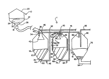
Figure 1 is side view in cross section of the waste treatment system.
In the drawings like characters of reference indicate corresponding
parts in the different figures.
DETAILED DESCRIPTION
Referring to the drawings, a waste treatment system 1 comprises a
waste source 10, a flow equalization tank 12, a reactor tank 14 and a
clarifier tank
16.
The waste source 10 provides waste 18 composed of waste liquid
containing solid content for treatment by the waste treatment system 1.
Specifically, the waste strength and the odour of the waste 18 are reduced by
the
waste treatment system 1 as described below. In this embodiment, the waste
source 10 comprises a barn 20 for holding livestock therein. The barn 20
includes
a manure pit 22 beneath the barn 20 for collecting the waste 18 from the
livestock
as described below. The manure pit 22 includes a surface sprayer 24, a waste
outlet 26, a waste duct 28 and a pump 30. The surface sprayer 24 is arranged
to
distribute a microbial additive 32 comprising a mixture of enzyme and bacteria
throughout the manure pit 22 for promoting solubilization and odour reduction
of
the waste 18. The waste outlet 26 is connected to the waste duct 28 which is
in
CA 02321857 2000-08-23
WO 99/43623 PCT/CA99/00171
7
turn connected to the pump 30. As a result of this arrangement, the pump 30
draws the waste 18 from the manure pit 22 out of the manure pit 22 through the
waste outlet 26 and along the waste duct 28, as described below.
The flow equalization tank 12 is arranged for mixing the waste 18
therein, thereby further homogenizing the texture of the waste 18. The flow
equalization tank 12 comprises a top 34, a base 36, a waste intake 38, a
storage
gas port 40 and a storage homogenizing system 42. The waste intake 38 is
arranged to accept the waste 18 from the waste source 10. In this embodiment,
the waste intake 38 comprises a baffle 43 located proximal to the top 34 of
the flow
equalization tank 12. The baffle 43 is arranged to be of variable height
relative to
the top 34 of the flow equalization tank 12. It is of note that the baffle 43
is
arranged to distribute the waste 18 from the waste source 10 into the flow
equalization tank 12 so as to promote mixing of the waste 18 therein. In this
embodiment, the baffle 43 has a substantially cone-like shape and the waste 18
is
applied directly onto the baffle 43. As a result, the waste 18 is distributed
as a thin
film over the baffle 43, thereby allowing for maximum waste surface area
exposure. The storage gas port 40 is arranged to remove gases emitted by the
anoxic and anaerobic bacteria during breakdown of the waste 18 from the flow
equalization tank 12 as described below. The storage homogenizing system 42 is
arranged to mix the waste 18 in the flow equalization tank 12. Specifically,
in this
embodiment, the storage homogenizing system 42 comprises a withdraw port 44
located at the base 36 of the flow equalization tank 12, a return port 46
located at
the top 34 of the flow equalization tank 12, a duct 48 interconnecting the
withdraw
CA 02321857 2000-08-23
WO 99/43623 PCT/CA99/00171
8
port 44 and the return port 46 and a chopper pump 50 coupled to the duct 48.
Thus, the chopper pump 50 draws the waste 18 out of the withdraw port 44 at
the
base 36 of the flow equalization tank 12 and shreds the waste 18 before
returning
the waste 18 to the flow equalization tank 12, thereby recirculating, mixing
and
homogenizing the waste 18.
In this embodiment, the storage homogenizing system 42 further
includes a siphon port 52 arranged to remove a portion of the waste 18 from
the
duct 48 and transport the portion of the waste 18 to the reactor tank 14 as
described below.
The reactor tank 14 is arranged for treating the waste 18, thereby
reducing waste strength and the odour of the waste 18. The reactor tank 14
comprises a top 54, a base 56, walls 57, a reactor inlet 58, a heat exchange
system 60, a reactor gas port 62 and a reactor homogenizing system 64.
In this embodiment, the reactor inlet 58 comprises a baffle 43 that is
arranged to distribute the waste 18 from the flow equalization tank 12 into
the
reactor tank 14 so as to promote mixing of the waste 18 therein as described
above. The heat exchange system 60 is arranged to heat the waste 18, thereby
reducing waste strength and odour of the waste as well as eliminating
pathogens
and producing treated waste 66 as described below. The reactor gas port 62 is
arranged to remove gases emitted from the treated waste 66 during heating as
described below. The reactor homogenizing system 64 is arranged to mix the
treated waste 66. In this embodiment, the reactor homogenizing system 64
comprises a withdraw port 68 located at the base 56 of the reactor tank 14, a
CA 02321857 2000-08-23
WO 99/43623 PCT/CA99/00171
9
return port 70 located at the top 54 of the reactor tank 14, a duct 72
interconnecting the withdraw port 68 and the return port 70 and a chopper pump
74 coupled to the duct 72. Thus, the chopper pump 74 draws the treated waste
66
from the base 56 of the reactor tank 14 and shreds the treated waste 66 before
returning the treated waste 66 to the reactor tank, thereby recirculating,
mixing and
homogenizing the treated waste 66. Specifically, the combination of heating
and
shredding of the waste 18 eliminates pathogens and stabilizes the waste such
that
no further breakdown of the waste occurs and no gases are released, as
described
below. In essence, the waste is stabilized following treatment.
In this embodiment, the reactor homogenizing system 64 further
includes a removal port 76 arranged to remove a portion of the treated waste
66
from the duct 72 and transport the portion of the treated waste 66 to the
clarifier
tank 16 as described below.
The clarifier tank 16 is arranged for accepting the treated waste 66
and separating the treated waste 66 info waste liquid 78 and waste solid 80.
The
clarifier tank 16 comprises a top 82, a base 84, a waste liquid outlet 92 and
a
waste solid outlet 94. The clarifier inlet 86 is arranged to accept the
treated waste
66 from the reactor tank 14 as described below. The waste liquid outlet 92 is
located at the top 82 of the clarifier tank 16 and is arranged for removing
the waste
liquid 78 from the top 82 of the clarifier tank 16 as described below. The
waste
solid outlet 94 is located at the base 84 of the clarifier tank 16 and is
arranged for
removing waste solid 80 from the clarifier tank 16 as described below.
The waste treatment system 1 is assembled as follows. The waste
CA 02321857 2000-08-23
WO 99/43623 PCT/CA99/00171
10
duct 28 is connected to the waste intake 38, the siphon port 52 is connected
to the
reactor inlet 58 and the removal port 76 is connected to the clarifier inlet
86.
In operation, waste 18 is produced by the livestock in the barn 20
and the waste 18 drops from the barn 20 to the manure pit 22. At this point,
the
waste 18 is of highly heterogeneous texture. Specifically, the waste 18 is
composed of a mixture of faeces, urine, feed, water, hooves, hair and after-
birth.
The waste 18 is approximately 50-75% biodegradable, consisting of
carbohydrates, proteins and fats, which is an ideal medium for microbial
growth.
As noted above, the surface sprayer 24 distributes the microbial additive 32
onto
the waste 18 at regular intervals. Specifically, the microbial additive 32 is
composed of a mixture of enzymes and microbes which will stimulate activity
within the waste 18. In one embodiment, the microbial additive comprises a
combination of enzymes and micro-organisms. The bacterial augmentation in the
manure pit promotes more anoxic/anaerobic processes than aerobic processes.
While aerobic conditions exist in the upper film of the waste in the manure
pit due
to surface contact with the atmosphere, this aerobic zone is almost
insignificant in
relation to the majority of the waste in the manure pit which is in an
anaerobic
condition. Specifically, the aerobic zone is small due to crust build-up on
the waste.
By using bacterial augmentation in the manure pit, solids are channelled
through
the bacteria and solubilized in the process. The formulated bacteria are
essentially
designed to assist the naturally-occurring bacterial populations in swine
waste to
solubilize the waste more rapidly and efficiently. In speeding up the
solubilization
process, the crusting is reduced and the odours released by anaerobic
breakdown
CA 02321857 2000-08-23
WO 99/43623 PCT/CA99/00171
11
of the waste are reduced. At intervals, the waste 18 is drawn through the
waste
outlet 26 and into the waste duct 28 by the pump 30. The waste 18 is then
deposited into the flow equalization tank 12 via the waste intake 38. Therein,
the
waste 18 is recirculated through the flow equalization tank 12 by the storage
homogenizing system 42. As a result of this arrangement, the waste 18 is mixed
and anoxic conditions exist. During this process, gases, for example carbon
dioxide, methane, ammonia, nitrogen gas and the tike are produced by the
anaerobic and aerobic bacteria. As noted above, these gases are removed from
the flow equalization tank 12 via the storage gas port 40. At regular
intervals, a
portion of the waste 18 is removed from the storage homogenizing system 42
through the siphon port 52 and the portion of the waste 18 is transferred to
the
reactor tank 14 through the reactor inlet 58. Therein, the waste 18 is heated
by the
heat exchanger system 60 to a temperature within the range of 40-70°C
for a
period of 12-36 hours, thereby producing treated waste 66. In this embodiment,
the
waste 18 is heated to approximately 60°C for approximately 24 hours.
Furthermore, the treated waste 66 in the reactor tank 14 is recycled by the
reactor
homogenizing system 64 and the gases emitted from the treated waste 66 in the
reactor tank 14 are removed via the reactor gas port 62. It is of note that
the
heating of the waste 18 combined with the shredding of the waste 18 eliminates
pathogens and promotes breakdown of the waste 18, that is, conversion of the
solid content of the waste 18 into colloid and solute fractions. Specifically,
the
combination of heating and shredding stabilizes the treated waste 66 such that
no
gases are emitted and the treated waste 66 is stabilized. It is of note that
treatment
CA 02321857 2000-08-23
WO 99/43623 PCT/CA99/00171
12
of the waste 18 occurs in the absence of added oxygen. Furthermore, tests
indicate that this process is most efficient at the natural pH, which is
anticipated to
obviate regular chemical additions to modify the pH of the waste 18. The end
result
is that the waste 18 is broken down to biomass material, carbon dioxide,
nitrate
and water and undissolved solids precipitate readily out of solution as a
result of
the heating and shredding. At regular intervals, a quantity of the treated
waste 66
is removed from the reactor homogenizing system 64 through the removal port 76
and transferred to the clarifier tank 16 via the clarifier inlet 8fi. Therein,
the treated
waste 66 separates into waste liquid 78 and waste solid 80. Furthermore, the
removal of the emitted gases also greatly reduces odours associated with
treatment of the waste 18 by the waste treatment system 1. Periodically, the
waste
liquid 78 is removed via the waste liquid outlet 92 at the top 82 of the
clarifier tank
1 C. It is of note that the waste liquid 78 may be used, for example, as
liquid
fertilizer. Similarly, periodically, the waste solid 80 is removed via the
waste solid
outlet 94 and dried. It is of note that the waste solid 80 may be pelletized
and used,
for example, as a dry fertilizer or as a feed supplement.
The end result of treatment of the waste 18 by the waste treatment
system 1 is that a substantial majority of the biodegradable portion of the
waste 18
is solubilized. Furthermore, odours produced from the waste 18 are limited by
the
waste treatment system 1 through the action of the reactor gas port 62 and the
storage gas port 40, which remove the malodorous gases produced by the
anaerobic bacteria from the reactor tank 14 and the flow equalization tank 12
respectively.
CA 02321857 2000-08-23
WO 99/43623 PCT/CA99/00171
13
It is of note that, in this embodiment, the waste treatment system 1 is
arranged to be a continuous flow system, wherein waste is removed from each of
the tanks simultaneously. Alternatively, the waste treatment system 1 could
also
be run in batch mode. Furthermore, no additional oxygen is added to the waste
treatment system.
In other embodiments, the waste solid outlet 94 may be connected to
a de-watering unit. The de-watering unit is arranged so that the waste solid
80 is
deposited onto the de-watering unit by the waste solid outlet 94 which forces
residual liquid out of the waste solid 80, thereby drying the waste solid 80
as
described below. Following de-watering, the waste solid 80 may be dried and
pelletized and used, for example, as a dry fertilizer or as a feed supplement.
In another embodiment, the gases removed via the storage gas port
40 and the reactor gas port 62 may be bubbled into the waste liquid 78 and the
waste solid 80 via gas injection means, thereby enriching the nutrient content
of
the waste liquid 78 and the waste solid 80 by recycling nitrogen.
In yet another embodiment, the liquid waste 78 may be stored in an
outdoor storage tank and the outdoor storage tank may include gas injection
means for bubbling gases removed via the storage gas port 40 and the reactor
gas
port 62 into the liquid waste 78, thereby conserving nutrient content, as
discussed
above. Alternatively, the gas could be cleaned and have odours removed by
using
a gas scrubber or filtration system.
In an alternative embodiment, the reactor tank 14 includes a vacuum
for generating a lower pressure zone in the reactor tank 14. As the pH range
of the
CA 02321857 2000-08-23
WO 99/43623 PCT/CA99/00171
14
treated waste 66 in the reactor tank 14 is approximately 8.5 to 9.5 and, as
noted
above, the waste 18 is distributed as a thin film, production of ammonia gas
within
the reactor tank 14 is maximized. Specifically, the factors that determine the
effectiveness of stripping ammonia out of water are pH, relative pressure,
temperature and film thickness. In the above-described arrangement, these
factors
are maximized for the liberation of ammonia gas from the treated waste 66. In
addition, other gases, for example, methane, carbon dioxide and water vapour
will
be liberated from the treated waste 66 as well. In operation, the gases are
forced
to move towards the lower pressure zone at the upper portion of the reactor
tank
14. The gases are then drawn out of the reactor tank 14 through the reactor
gas
port 62. Once removed from the reactor tank 14, the gases are transferred to a
condensor tank wherein the gases are cooled and condensed back into liquid
form. The resulting product is therefore a highly condensed nutrient rich
liquid
fertilizer. Furthermore, the treated waste fib remaining in the reactor tank
14 is
processed as described above, thereby producing waste liquid 78 and waste
solid
80 having a low nutrient content. As a result, the waste liquid 78 and the
waste
solid 80 may be applied in large volumes without fear of groundwater and
surface
contamination. Furthermore, the condensed nutrient rich liquid fertilizer can
be cost
effectively transported and applied to farm land significant distances from
the
swine production site.
An alternative waste source may be human waste or any other high
strength waste.
Since various modifications can be made in the invention as herein
CA 02321857 2000-08-23
WO 99/43623 PCT/CA99/00171
15
above described, and many apparently widely different embodiments of same
made within the spirit and scope of the claims without department from such
spirit
and scope, it is intended that all matter contained in the accompanying
specification shall be interpreted as illustrative only and not in a limiting
sense.