Note: Descriptions are shown in the official language in which they were submitted.
CA 02322029 2000-08-21
1
DUAL-POLARIZED DIPOLE ANTENNA
The invention relates to a dual-polarized
dipole radiator according to the preamble of Claim 1.
It is known that two orthogonal polarizations
can be emitted or received by means of dual-polarized
antennas. If the two systems are connected up
appropriately, they can also be used to emit or receive
any other desired combinations of the linear orthogonal
polarizations such as, for example, a circular
polarization.
Dual-polarized antennas normally have dipole
radiators, patch radiators or slot radiators as primary
radiators. With dipole radiators, it is essentially the
dipole square, comprising four individual dipoles, and
a turnstile dipole arrangement which are applied as
structures. The said radiators can thereby be operated
both horizontally and vertically, as well as with a
polarization alignment at an angle of ~45°. In this
case, one also speaks, for example, of an X-polarized
antenna, as is known in principle from DE 1296 27 015.
There are problems with such types of dual
polarized antennas when, for example, the aim is to
implement half-widths of less than approximately 75° in
conjunction with a compact antenna design. In this
case, it is possible to implement dual-polarized
antennas virtually only by means of dipole squares
and/or by using very wide reflectors. This is
associated with a not inconsiderable wiring outlay.
Thus, for example four cables have to be used for
feeding the dipoles. The large antenna dimensions are
also disadvantageous, however, particularly owing to
the wide reflectors which are required.
CA 02322029 2002-07-22
7 _
A further di=advantage consists, in particular
in the case of ~45°-po:Larized dipole antennas, in that
there is a relatively high coupling iro the case of an
array arrangement comprising dipole squares. This
relatively high coupling has a disturbing effect,
particu:Larly in the case of antennas with a tunable
phase relationship of the dipoles (adjustable electric
downtilt).
A further embodiment of dual-polarized
radiators has been disclosed, for example, in
EP 0 685 900 Al. This i~> a slot radiator which can be
appropriately excited. However, the limiting
dimensioning of the sl.ot/feed coupling required in this
case renders it possible to implement small half-widths
only by means of correspondingly large ref:Lectors even
in the case of thi:> known prior art.
Starting from the prior art mentioned at the
beginning, it is therefore the object of the present
invention to create a dual-polarized dipole radiator
which is of simple design and, i_n particular, has an
improved decoupling even in the case of an array design
when use is made of a plurality of du<~1-polarized
radiator modules.
The obj ect- i ~ ac::hi eved ~cc_~ord iaq t~c~ the invention
in accordance with the Ieatur_es :~pc-~~_:i E i ed in the present
description.
According to 1-he present ir.venti.on, there is
provided a dual-polarised radiator arrangement comprising:
a plurality c:f ~_ii~~oles whi~:.:h ;m:e a:rranged to form
a dipole square,
a plural:i.ty of ~ubstantiv~lly symmetrical feed
lines that feed the plurality of ~li_pc:~les,
wherein the radiator ~:rrangemer~t formed in the
shape of a dipole squa:ee is connecte~~t i.~ such a way and fed
CA 02322029 2002-07-22
- 2a -
in such a way that thE: dipole square radiates electrically
in two polarization r>la~nes si.muoltaneouslv which are
mutually perpendicular and ewu parallel to the two mutually
perpendicular diagc>nals formed by thc~ dipole square.
Preferably, true i:~lurality of- ind.iv:idual dipoles
are arranged upstream of a ref lector r<, struct.urally form
the dipole square in top view, each dipole of the plurality
of dipoles being fed by ~n associate's symmetrical feed
line, wherein:
the dual-polarized dipole radi_at:or radiates
electrically in a polarization at: ari amble of +45° or -45°
to the st=ructurally presc:rikved al ic~nznent of t:he dipoles;
the ends of th~~ :~ux~st<ant:ially symmetrical lines
leading i.o the respective dipole halves .:ire co:~r,ect~ed up in
such a way that the cc~?rz espondi.rla ' ine halves of the
adjacent, mutually perpendicular dipo_Le halves are always
electrically connected; and
the electric ft~eding of the respectively
diametrically opposite dipole halves is performed in a
decoupled fashion wor <~ fi.rst L~olar_i z~:tz_on and a second
polarization orthogonal thereto.
Preferably ~~.lsc>, the d_~al--L,~olarized radiator
arrangement comprises a plural-i!,~y of Lndividual dipoles
which are arranged upstream of a ref lec:Tc,r and structurally
form a dipole square irl top view, each dipole being fed by
said substantially :>ymmetric,~1 1_irre wtuer~ein:
the dipole radiator ele~~tr~_c:ally comprises a
turnstile dipole and strlictux:~ally simulates a dipole
square,
the electrically respectivc,ly single dipole half
is structurally formed respect.iveiy from two half dipole
CA 02322029 2002-07-22
components which are aligrved irn a rnut:ually perpendicular
fashion and are respect.ivel.y E~lectr~=i cal.ly fed vi.a an
electric line half; and
in each case tw:~ ad j acent :Line halve:, which
serve to fed two adjacent half d:ipc~l.e components mutually
aligned in an axial extension, are respectively arranged
with a lateral. offset rurming parallel. or subst:antially or
approximately parallel to one an~~ther.
According to yet another aspect of the present
invention, there is also ~ar~:.vi.ded a dual--polarized radiator
arrangement, having the f~~llowing fe,~l=nrf>s:
the radiator arrangement c~~~mprises a plurality of
dipoles which ar_e arranged in top view with the formation
o.f a dipole square,
each dipole i~ fed by rrmans of a symmetrical
line,
characterized by the following further features:
the radiator arrangement. formE:<~ in the shape of a
dipole square is connected up in :~ucr: a way and fed in such
a way that the ~~i.pole :~qa~are racii.:~t:a--=s Felectrically in two
polarization planes which are m;.~tu_~l.ly perpendicular and
run parallel to the two mutually perk>endicular diagonals
formed by the dipole :square, ch~:.~r~-zctf~rized in that. she
symmetrical feed lines ar.-e formc_d from in each case two
identical asymmetric line ha.l.ves.
According to yet; another aspect. of t:he present
invention, there is also 1~~rovided a dual--pol~~ri.zed .radiat:or
arrangement, having the foll~:~wing features:
the radiator arran:~ement_ c:c:,rnpri ses a plurality of
~~ipoles which are arrar~dec~ ~ n top vi ew ~f~ith the formation
of a dipole square,
CA 02322029 2002-07-22
each dipole is eci by mean ~ of a symmetrical
line,
characterized by t:he fcl:lc>cN~ing further features:
the radiator arranqement formed i.n the shape of a
dipole square is connected up in such a way and fed in such
a way that the dipole square radlat_es electrically in two
polariz anon planer w:zi.<-h are rnuti:~ally pe:rpf~ndicular and
run parallel tc the t=wo mutual.:ly perpendi~zular diagonals
formed by the dipole sdua~_e, c,-.har<-3cterizec~ in that, the
symmetrical feed l inet: '~:im~.zlt.aneou:~ l y t;: orm the mechanical
holder of the dipoles.
According to yet another asps>ct of the present
invention, there is also prcovi.ded a dual-polarized radiator
arrangement, having the: following te~tu~~es:
the radiator are:~angemer~t c~:>mpr:.ses a plurality of
dipoles which are arrancxed in trop v _ew with the formation
of a dipole square,
each dipole is fed by means of a symmetrical
line,
characterized by the following further features:
the radiator arrangement. f;rmecl in the shape of a
dipole square is connected up in ~~zc!u ~~ way anc~ fed in such
a way that the dipole ~sqi_~are radiat<»v electrically in two
polarization planes; whi.ctr are mutually perpendicular and
run parallel t=o the two mi:,tually leerpendicular diagonals
formed by the dipole squ<~re,
characterized ix~. that the syrrmet:rival feed lines
lie in the same plane as <~r a plague: ~-~arai 1.e1 to that: of the
dipoles, which is locate~~l upstream oT a reflector.
CA 02322029 2002-07-22
G ._~
According tc> yet another a~~pect o~_ the present
invention, there is also provided a dua~.-polarized radiator
arrangement, having the foll.owi.nc~ features:
the radiator arrangement c..-ompri.ses a plurality of
dipoles which are arr~~ngad in top ~,.rie~a with the formation
of a dipole square,
each dipole is .ted by means of <~ symmetrical
line,
charac:teri zed by t he f~~ l :Lowing furi_her features
the radiator ar~:arngement formed in the shape of a
dipole square is connected czp .in s~.m:~u a way and fed in such
a way that the dipole square raeliat:es r=:leci~r=_cally in two
polarization planes which are mutually perpendicular and
run parallel to tre t.wo m~.zt~..~al:iy x~erpE~ndic:u_ar diagonals
formed by the dipole square,
characterized in that ~.he syrnmetri_cal feed lines
are arranged running incl:inad 1:.o a zcflc:~rton plate and are
aligned falling at least slightly 3.r~ the direction of the
dipoles to be fed.
According to yet another aspEV:ct of the present
invention, there is also provided a dual-pol<~r=ized radiator
arrangement, having the f<:~llowing fe~ilvurE:=s:
the radiator arw:an~ernent c~.>rnpr::i ses a plurality of
dipoles which are arra.~ged in top view with the formation
of a dipole square,
each dipole is f~~d by mE~an:~ of a symmetrical
line,
characterized L~y ttne fo1_lowing further features:
the radiator arran~~ement fc, rmed in the shape of a
dipole square is connected up ir- ~uclu a way anc'. fed in such
way that the dipole sqc.zare radiates a Lectri~~a~.ly in two
CA 02322029 2002-07-22
polarization planes wh_ia:h are rnt.at~.~a7.:Ly perpendicular and
run parallel to the two n~utualls~ perpendicular diagonals
formed by the dipole sguare,
characterized i.n that the intercortnec;tion of the
symmetrical feed lines is provideca <mn tr.e ~~ide of the
reflector averted from the dipoles.
According to yet <~not.he.r aspsrct of the present
invention, there is also pr_~>v:ided a c~u~il-polarized radiator
arrangement, having the fol_owing features:
the radiator arrangement comprises a plurality of
dipo l es which are arrG.nged in tc:~p v i_ew with the formation
of a dipole square,
each dipole is ied b~,; means of a symmetrical
line,
characterized b~r~ the fo L l.ow_inc~ further features
the radiat=or art angement_ formed in the shape of a
dipole square is connected tap in smch a way anti fed in such
a way that the dipole squal a radiates c~lectrlcally in two
polarization planes wr.ich are mutually perpendicular and
run parallel t:o the t.wc:~ mt:~tually ~_~erpF~ndicula.:~ diagonals
formed by the dipole squ~xre,
characters zed __:i that the ir;terconnection point
of the symmetrical feed lines is i_rarm~formed by a ba:lun
coupled to an asymmetric Feet c:aba e.
According to yet another aspect of the present
invention, there is also p.rovidect a c~ua:L--pol~~ri.zed :radiator
arrangement, having the fc,ll:~wi.ng features:
the radiator .~.rrangement comprises a plurality of
dipoles which are arranged in top view with the formation
~~f a dipole square,
CA 02322029 2002-07-22
- 2f -
each dipole i=~ Eed key rnean:~ of a symmetrical
line,
chara<;terizec~ kvy ~~he fc:llowi..ng further features:
the radiator arra=ugemervt formed in the shape of a
dipole square is connected _ip .in suc_;h a way and fed in such
a way that the dipole square radiataes electrically in two
polarization plane; whi.c:ln are rnut:t.aa.:ll.y perpen.d~cular and
run parallel to the two mutuai~y perpendicular diagonals
formed by the dipole square,
further c:har_acterized in that the ends of the
half dipole components, which are mutually orthogonal, are
mechanically connei~ted, and the mechanical connection of
the dipole ends is electr:icatll.y noncondu.:~ting.
According to ~,ret anott~:er aspt,ct of the present
invention, there is al:~o prc>vz.ded a ~:~tzal-polarized radiator
arrangement, having the foll..owin~.l features:
the radiator arz:~angement ccampri.ses a ~>lurality of
dipoles which are arranged in top view with i~he formation
of a dipole square,
each dipole is fed by means of a symmetrical
line,
characterized by the following further features:
the i:adiat:.or arrangement f<;rme~c:1 in the shape of a
dipole square is connected up in :~uctv a way and fed in such
a way that the dipc:ale srlu.raze radiat.c~s ~~1_ectrica.lly in two
polarization planes whic:lo are mutually perpendicular and
run parallel to the two mt:atual.l. y ~:ae:rpendi.cular diagonals
formed by the dipole square,
characterz.zed in that the interconnection of the
dipoles is performed by a printed ciw::uit .
CA 02322029 2002-07-22
-
According to yet another aapect o:E the present
invention, there is also provided a dua:l_-po_Larized radiator
arrangement, having the j-of l_ow.in~7 fc~at~.°;x es
the radiator a.r_.rangemer~t comprises; a plurality of
dipoles which are arranged in t=op ~,~iew with the formation
of a dipole square,
each dipole i.s fed by mearm of <~ symmetrical
line,
character.izec~ by the f=o:l..:Lowing further features:
the radiator arrangement f~~rmed in the shape of a
dipole square is conneatFd yap in suchu a way and fed in such
a way that the dipole square ra~aa.ai es f:=~leci_ricall_y in two
polarization planes which are rr~utz7ally perpendicular and
run parallel to the t:wo rnutl.zal i y l.~er;omdic~u_Lar diagonals
formed by the dipole square,
characterizes:. in what t_he feeding with reference
to t:he respectively o~po:v,ite ru:~l.ves c,:E they balun is
performed by an eler..trical 1y ~-onc~iuctinq bridge not in
mutual electric contact., which is rE=_:~.pectivel_y mechanically
held with one of its erarts oro tFOe ~-~ssoa~iatf=d half of the
balun and is electric:aily connected to the latter, and
projects with its respective oppos:i t;e ' ree end through a
bore in the assoc:iatc~d opposites half of the balun for
leading through an electric feed, and
wherein at:. ttve oe: pest: i Ve f ree end of the bridge
the electric feed is performed by means o:E the electric
contact with an electric ~~onc~uctor, :_.n particular the inner
conductor of a coaxial. c:abJ e, th:e c.~utE~r condac:tor of the
coaxial cable prefei:ab:Ly making ele~vt.r.ia:~ contact with the
half of the balun not rnaking electric contact with t=he
associated bridge.
CA 02322029 2002-07-22
-
According to ;Jet another aspect of the present
invention, there is alsa~ provided a dua i.-po:_arized radiator
arrangement comprising:
four dipoles arranged :in dipole square, the
dipole square simultaneously radi.at:ing electrically in both
a +45° polarization and a -~5° pc;laz-izat:ion with respect to
at least one axis,
a feed line arrangement co~.ipled to the four
dipoles, the feed line arrangement including a first set of
adj acent and paral 1e1. f eed l.i.ne conductors a.nd a further
set of feed line conc!uctors, the first set. of feed line
conductors overlapping i.r~ terms of ~~hase with the current
of the further_ set of feed line conductors such that the
further set of feed li.rne c:onductor~ u;le> nc.>t a'_sc> radiate,
wherein the first set of treed line conductors is
connected to the dipc;le square at a first set of feed
points, the second set of feed f_i.nc:s i~ conne<~ted to the
dipole square at a second set of feed points, and the first
and second set of feed poiruts ar.e decoupled :E.rom one
another due to superposit f on o.f clzrrf_ nt~~ .
According to the pr_eser~t: invent ion, there is also
provided the follo~a~ nc~ pref erred embodiments <~nd
advantages.
The dual-polarized dipole radiators according
to the invention are of simpler design by comparison
with conventional solutions, with t_he result that the
dipole radiators according to the i.nventicn can be
produced more cost-effectively, for ones thing.
However, they also exhibit: a completely
surprisingly structure which differs from conventional
CA 02322029 2002-07-22
- ~l -
solutions which yield [sic] improved values for
decoupling, chiefly in the implementation of an antenna
array.
What is surprising is that the dual-polarized
dipole radiators according to the invention act
CA 02322029 2000-08-21
- 3 -
electrically like a turnstile dipole, but more resemble
a dipole square in terms of mechanical design.
It is furthermore surprising that, given dipole
components which are aligned horizontally and
vertically, the antenna module which more resembles a
dipole square in terms of its spatial design results
electrically in an X-polarized antenna module, in other
words an antenna radiating electrically at ~45°.
If, by contrast, the antenna is to radiate or
receive in a polarized fashion in the horizontal and/or
vertical direction, that is to say the turnstile dipole
is to be aligned electrically with its electric dipole
axes in the horizontal and vertical directions, it
would be necessary for the module, which more resembles
a dipole square in terms of design, to be aligned with
the individual dipole components in a ~45° direction.
The invention provides for this purpose that
each of the four dipoles is fed by a symmetrical line,
and that owing to the special type of interconnection
the mutually orthogonal adjacent dipole halves of two
adjacent dipoles are respectively excited in phase.
These symmetrical or at least essentially or
approximately symmetrical feed lines comprise two line
halves which, viewed individually, constitute an
asymmetric line with respect to a fictitious zero
potential. The interconnection of the asymmetric line
halves is performed according to the invention in such
a way that the two line halves leading to two adjacent
dipole halves aligned in a mutually orthogonal fashion
are electrically interconnected in each case. The
feeding of the resulting overall radiator is performed
in this case in a crosswise fashion. That is to say,
the two connected line halves, respectively mentioned
above, of two mutually perpendicular dipole halves are
respectively electrically interconnected in a crosswise
fashion with the two line halves of the diametrically
opposite adjacent and mutually orthogonal dipole
halves, preferably in a crosswise fashion [sic]. The
overall radiator therefore acts electrically rather
CA 02322029 2000-08-21
- 4 -
like a turnstile dipole, the lines proceeding from the
middle not also radiating, or doing so only negligibly
owing to their special design. It is possible to this
extent to interpret the respectively mutually
orthogonal adjacent dipole halves, which are excited in
phase, after all, as part of a resulting turnstile
dipole. For this reason, the radiator designed
according to the invention is also designated as a
tCJU11.111Cj ~uttmlle aipole. 1L 1S nOW Completely
surprising that a wideband high decoupling is achieved
between the feed points in the first polarization and
in the second polarization, which is orthogonal
thereto.
The abovementioned symmetrical feed lines
connected to the respective dipole halves are
preferably of symmetrical design, resulting in the
preferred symmetrical line arrangement since, as
mentioned, the associated line halves are arranged per
se asymmetrically relative to one another with respect
to a zero potential and are fed in antiphase. The
advantages according to the invention are, of course,
still achieved in this case whenever the symmetrical
feed line is not 1000 symmetrical, but deviates
therefrom, the degree of decoupling decreasing with
increasingly stronger deviation from the symmetrical
design of the feed lines.
In a preferred embodiment of the invention, the
respective line half, leading to the dipole, of the
symmetrical feed line is constructed as a mechanical
holder of the dipole halves, and said holder is
situated or terminates preferably at the same distance
above the reflector at which the dipole itself is
fitted above the reflector. This line can therefore
also be interpreted as part of the resulting turnstile
dipole, but owing to the antiphase currents on the line
halves said line does not radiate, or does so only
slightly. This results, therefore, in the desired
elimination of the radiation activity and thus in a
better focusing of the dipoles. Consequently, it is
CA 02322029 2000-08-21
- - 5 -
completely surprising that the corresponding
connecting-up in a crosswise fashion at the feed point
then results, on the one hand, in emission of the
polarization lying in a ~45° plane and, on the other
hand, in a wideband high decoupling.
The symmetrical feed lines are preferably
arranged with their in each case two asymmetric line
halves such that in a top view of a radiator
arrangement said line halves proceed from a balun
situated approximately in the middle and lead to the
respective two connecting points of two dipole halves
situated in an axial extension with respect to one
another. These feed lines can, however, also be
arranged in a fashion running completely differently.
For example, it is also possible to lead these line
halves of the symmetrical feed line from the rear side
of a reflector plate through the latter, the line
halves leading, for example, approximately
perpendicular to the plane of the reflector plate
directly to the connecting points, located thereabove,
of the dipole halves respectively situated in an axial
extension. The holding device for the dipole halves can
likewise be constructed completely separately from the
line halves connected to the dipole halves.
The respectively two mutually perpendicular
half dipole components are usually arranged such that
they respectively point with their free ends to a
common intersection which forms the corner points of a
square. The components of the dipole halves need not be
structurally connected here, but they can be. In this
case, the components can be metallic or can be
connected by using insulators which are seated at the
corner points of the abovementioned square.
The invention is explained in more detail below
with the aid of exemplary embodiments. In this case, in
detail:
Figure 1 shows a diagrammatic top view of a dipole
square according to the prior art;
CA 02322029 2000-08-21
- 6 -
Figure 2 shows a diagrammatic top view of a dual-
polarized dipole radiator according to the
invention with an electric polarization of
~45°;
Figure 3 shows a perspective illustration of an
exemplary embodiment, shown in concrete
terms, of a dipole radiator according to the
invention;
Figure 4 shows a diagrammatic side view of the dual-
polarized dipole radiator according to the
invention; and
Figure 5 shows a diagrammatic top view of an antenna
array with a plurality of dual-polarized
dipole radiators according to Figures 1 and
2.
In order to illustrate the differences
according to the invention from a conventional dual-
polarized dipole radiator, reference is firstly made to
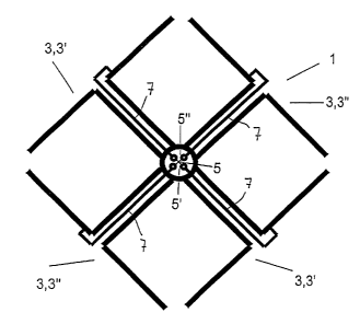
Figure 1, in which a dual-polarized dipole radiator 1
of this type is shown in the form of a dipole square.
The dipole radiator 1, known according to the
prior art, in accordance with Figure 1 is designed such
that its dipoles 3 can receive or emit linear
polarizations at an angle of +45° and -45° referred to
the vertical or horizontal. Such antennas or antenna
array [sic] are also designated for short as X-
polarized antennas or antenna arrays.
In accordance with Figure l, first dipoles 3"
in a -45° alignment and second dipoles 3' in a +45°
alignment are provided in a fashion respectively
situated offset from the axial center point 5 of the
antenna arrangement. It is indicated in Figure 1
diagrammatically that in this case the two opposite
dipoles 3' and 3" , respectively, are combined in each
case to form a double dipole. As a result, a total of
CA 02322029 2000-08-21
four connecting lines 7 are required in order to
undertake feeding of the two polarizations starting
from the center point 5, that is to say from the feed
or interconnection points 5' and 5" , respectively,
situated in the region of the center point 5.
A first exemplary embodiment according to the
invention of a dual-polarized dipole radiator is now
shown with the aid of Figures 2 to 4.
As discussed further in detail below, the
dipole radiator illustrated in Figure 2 acts
electrically like a dipole radiating with a
polarization of ~45°, that is to say as a turnstile
dipole, for example. The radiator acting electrically
as a turnstile dipole 3 is drawn in with dashes in
Figure 2. This radiator acting electrically as a
turnstile dipole 3 and having a ~45° alignment with
respect to the horizontal is formed by an electric
dipole 3' (inclined in a +45° direction) and,
perpendicularly thereto, a dipole 3" (inclined at -45°
with respect to the horizontal). Each of the two
electrically formed dipoles 3' and 3" respectively
comprises the associated dipole halves 3' a and 3' b for
the dipole 3' as well as the dipole halves 3" a and
3" b for the dipole 3" . Structurally, in this case the
electrically resulting dipole half 3'a is formed by two
mutually perpendicular half dipole components 114b and
llla. In the exemplary embodiment shown, the half
dipole components 114b, llla terminate with their ends,
running toward one another at right angles, at a
distance from one another. However, they could also be
connected there, specifically both by an electrically
conducting, metallic connection, and by inserting an
electrically nonconducting element or insulator, in
order, for example, to ensure higher mechanical
stability. It is also possible further to provide the
ends of the dipole halves with bends.
In a corresponding fashion, the dipole half
3" b, which is next in the clockwise direction, of the
electric dipole 3" provided electrically with a -45°
CA 02322029 2000-08-21
g _
alignment is formed by the two half dipole components
111b and 112a. The second dipole half 3'b formed in an
extension relative to the dipole half 3' a is formed by
the two half dipole components 112b, 113a and the
fourth dipole half 3" a is formed analogously by the
two half dipole components 113b, 114a.
The half dipole components arranged as a dipole
square are now fed by respectively one symmetrical feed
line 115, 116, 117 or 118. In this case, the two half
dipole components 114b and llla, for example, that is
to say in each case the adj acent mutually orthogonally
aligned half dipole components, are excited in phase
via a common feed point, here the feed point 15' . The
connecting lines belonging to these half dipole
components 114b, 111a respectively comprise two line
halves 118b and 115a which, viewed individually,
constitute an asymmetric line with respect to a
fictitious zero potential 20. In a corresponding
fashion, the two nearest half dipole components lllb
and 112a are, for example, electrically connected to
their common feed point 5" via the line halves 115b
and 116a, respectively, etc. In the case of this
connecting-up, the respectively associated symmetrical
feed line is simultaneously shaped such that it takes
over the mechanical fixing of the dipoles, that is to
say the half dipole components. In this case, for
example, of the symmetrical line 115 one asymmetric
line half 115a bears the dipole half llla, and the
second line half 115b, which runs preferably parallel
and is electrically separated from the line half 115a
bears the second dipole half lllb. In other words,
thus, in each case the two associated asymmetric line
halves belonging to a symmetrical line 115 to 118 bear
in each case the two dipole halves, arranged in an
axial extension relative to one another, of a dipole
111 to 114. By virtue of the fact that the line halves
which lead to the respectively adjacent mutually
orthogonal dipole halves are connected in an
electrically conducting fashion at their feed point,
CA 02322029 2000-08-21
- 9 -
four interconnection points 15', 5" , 15" , 5' are
produced which are fed, in turn, symmetrically in a
crosswise fashion, as follows, in particular, from the
illustration in accordance with Figure 5. The overall
radiator resulting therefrom now acts electrically like
a turnstile dipole owing to the in-phase excitation of
the half dipole components 114b, llla or the half
dipole components lllb and 112a or 112b and 113a or
113b and 114a. The specific arrangement of the line
halves which are arranged in each case parallel to one
another at a slight distance with the current flowing
therein in antiphase ensures that the line halves
themselves do not deliver any appreciable radiation
contribution, any radiation thus being extinguished by
overlapping.
The basic design in a top view of the radiator
arrangement in accordance with Figure 2 shows that the
radiator module has a fourfold symmetry in top view.
Two mutually perpendicular axes of symmetry are formed
by the symmetrical lines 115 and 117 or 112 and 118,
the third and fourth axis of symmetry in a top view of
the radiator arrangement in accordance with Figure 2
moreover being situated rotated by 45° and being formed
by the dipoles 3' and 3" which result electrically.
Furthermore, Figure 3 also shows at the feed
and interconnection point 5' the respective one part of
the balun 21 and, at a slight distance opposite
relative to the center point 5, the other part of the
balun 21a which, on the one hand, serves to fasten the
dipole structure mechanically to the reflector plate
and, on the other hand, permits the transition to
asymmetric feed lines (for example coaxial lines) at
the interconnection point.
It is shown correspondingly, particularly in
Figure 3, that the interconnection point 15' for the
half dipole components 114b and llla as well as the
opposite interconnection point 15" for the half dipole
components 112b and 113a is formed in the region of the
balun 22 and 180° or opposite thereto in the case of
CA 02322029 2000-08-21
- 10 -
the balun 22a, which likewise once again on the one
hand serves the purpose of fastening the dipole
structure mechanically to a rear reflector plate 33
and, on the other hand permits the transition to the
asymmetric feed line (for example coaxial line) at the
interconnection point. In this case, it is to be seen
very well in Figure 3, in particular, how the electric
feeding is performed via a crossover circuit with a
first circuit bridge 121 and a second circuit bridge
122, offset by 90° thereto, on the respectively
opposite baluns 21 and 21a or 22 and 22a, respectively.
The circuit bridges 121 and 122 last mentioned are
arranged at a vertical distance relative to one
another, that is to say are not interconnected
electrically.
It is also to be gathered in this case from
Figure 3 that, for example, the pin-shaped bridge 122
is fitted firmly mechanically on the half of the balun
22 situated at the rear in Figure 3, and is connected
there electrically to the balun 22, whereas the
opposite free end of this pin-shaped bridge projects
through a bore, of appropriately larger dimensions,
through the front half of the balun 22a, without being
electrically connected to this balun 22a. This opens up
the possibility of leading up a coaxial cable in front
of the balun 22a for feeding purposes, of connecting
the outer conductor electrically to a suitable point on
the balun, and of connecting the inner conductor at the
free end of the bridge 121 and effecting the feeding
thereby. The second parts [sic] of the bridge 121 is
also correspondingly designed, that is to say is fitted
mechanically with its rear end on the balun 21 and
electrically connected thereto, whereas the opposite
free end projects through a bore of larger dimension
without making electric contact via the balun 21a
situated front right in Figure 3. There, the second
coaxial cable can be laid, coming from below, parallel
to the balun, for example, the outer conductor can be
connected electrically to the balun, and the inner
CA 02322029 2000-08-21
- 11 -
conductor can be connected to the free end of the pin-
shaped bridge 121.
It may be mentioned merely for the sake of
completeness that other connection possibilities are
likewise also possible, for example, in such a way that
an inner conductor is led upward from below between the
respective baluns, and is then connected electrically
at a suitable point on the upper end of an assigned
balun, in order to permit symmetric feeding thereby.
The outer conductor can also be led via a part of this
section, or can already be electrically conducted lower
down to the respectively opposite half of the balun.
The possible transformations of the feeding are thus
explained only by way of example.
In other words, the feeding is thus performed
in a crosswise fashion between the feed points 5' , 5"
and 15', 15" , respectively. The abovementioned
electric line halves 115a to 118b are respectively
arranged in this case symmetrically relative to one
another in pairs, that is to say the adjacent electric
line halves of in each case two adjacently situated
half dipole components run parallel to one another at a
comparatively short distance, this distance preferably
corresponding to the distance 55 between the ends,
respectively pointing toward one another, of the
associated dipole halves, that is to say, for example,
the distance between the ends pointing toward one
another, of the dipole halves llla, lllb etc. It is
fundamentally possible in this case for the line halves
to run parallel to a rear reflector plate in the plane
of the half dipole components. In a departure from
this, the exemplary embodiment in accordance with
Figures 2 and 3 shows a design in the case of which the
line halves, which also constitute the holder device
for the half dipole components, are mounted falling
slightly starting from their assigned balun and
terminate at the level of the half dipole components,
which can be arranged parallel to a rear reflector
plate 33. This is associated with the wavelength region
CA 02322029 2000-08-21
- 12 -
of the electromagnetic waves to be transmitted or
received, since the height of the balun above the
reflector plate 33 is intended to correspond to
approximately 7~/4 and, if appropriate, it can be
desirable with reference to the radiation pattern that
the dipoles and dipole halves are to be arranged closer
opposite the reflector plate 33.
Consequently, on the basis of this arrangement
a dipole always acts simultaneously for the +45° and
the -45° polarization, although in a departure from the
three-dimensional geometrical alignment of the
individual half dipole components in the horizontal and
vertical direction the resulting +45° polarization or
-45° polarization, in other words, thus, the X-
polarized turnstile dipole radiator 3 drawn in
electrically in Figure 2 is not produced until the
radiator components are combined. The basis for the
mode of operation is that the currents on the feed or
connecting lines situated respectively adjacent and
parallel to one another, that is to say, for example,
on the electric lines 115a, overlap in terms of phase
with the current on the electric line 115b and the
current on the line 116a with that on the electric line
116b etc. such that the latter do not also radiate, or
do so only slightly; at the same time, the
superimposition of the currents at the feed points
produces a decoupling of the feed points (5', 5" ) from
the feed points (15', 15" ).
It is illustrated with the aid of Figure 5 that
it is also possible by making use of a dual-polarized
dipole radiator 1 explained with the aid of Figures 2
to 4 to design an appropriate antenna array with a
plurality of dipole radiators 1 which are arranged, for
example, one above another in a vertical fitting
direction and which describe altogether an antenna with
an electric polarization of +45° and -45° despite the
horizontally and vertically aligned half dipole
components.
CA 02322029 2000-08-21
- 13 -
The radiator arrangements shown in Figure 5 are
in each case arranged with their associated balun on a
reflector plate 33 which are [sic] provided in the
fitting direction of the individual radiator modules on
the opposite sides with electrically conducting edges
35 running perpendicular to the reflector plane.
In a departure from the exemplary embodiment
according to Figures 2 to 5, it is, however, equally
possible to undertake the electric feeding on the
dipole halves not in the region of the balun and the
line halves electrically fastened on the balun 21, 21a
or 22, 22a and simultaneously performing the holding
function. In a departure from this, it is possible that
the elements 115a to 118b denoted in Figures 2 to 5 are
constructed only as nonconducting bearing elements for
the dipole halves, and the symmetrical lines 115 to 118
takes place [sic] directly from below through the
reflector plate 33 to the connecting ends 215a, 215b,
216a, 216b, 217a, 217b and 218a, 218b. Finally, it is
likewise conceivable that in such a case the bearing
elements 115a to 118b for the dipole halves are
configured completely differently structurally, and are
arranged running in a different way, for example to run
[sic] from the connecting points 215a to 218b onto the
reflector 33 vertically or obliquely downward starting
from the middle of the dipole halves or from the corner
region of the respectively mutually perpendicular
dipole halves, and are mechanically anchored there.
Furthermore, it is also conceivable in a
deviation from this that the reflector itself is
constructed as a printed circuit board, that is to say,
for example, as the top side of a printed circuit
board, on which the overall antenna arrangement is
built up. The corresponding feeding can be undertaken
on the rear of the printed circuit board, the electric
line halves running on a suitable path, starting
therefrom, to the abovementioned connecting points 215a
to 218b. To achieve as good a radiation pattern as
possible, it is required only to ensure that
CA 02322029 2000-08-21
- 14 -
irrespective of the way in which they are led to the
connecting points on the dipole halves, these line
halves are aligned parallel to one another as far as
possible, that is to say substantially or at least
approximately, in other words that a symmetrical line
is substantially or approximately produced.