Note: Descriptions are shown in the official language in which they were submitted.
CA 02322039 2000-08-18
W(3 99/44246 PCTNS99/02593
s
5 Field of the Invention
This invention relates to electrochemical cells
and batteries, and more particularly, to lithium ion cells
and batteries.
Lithium batteries are prepared from one or more
lithium electrochemical cells. Such cells have included an
i5 anode (negative electrode), a cathode (positive electrode),
and an electrolyte interposed between electrically
insulated, spaced apart positive and negative electrodes.
The electrolyte typically comprises a salt of lithium
dissolved in one or more solvents, typically nonaqueous
(aprotic) organic solvents. By convention, during
discharge of the cell, the negative electrode of the cell
is defined as the anode. During use of the cell, lithium
ions (Li+) are transferred to the negative electrode on
charging. During discharge, lithium ions (Li+) are
transferred from the negative electrode (anode) to the
positive electrode (cathode). Upon subsequent charge and
discharge, the lithium ions (Li+) are transported between
the electrodes. Cells having metallic lithium anode and
metal chalcogenide cathode are charged in an initial
condition. During discharge, lithium ions from the
metallic anode pass through the liquid electrolyte to the
electrochemically active material of the cathode whereupon
electrical energy is released. During charging, the flow
of lithium ions is reversed and they are transferred from
the positive electrode active material through the ion
conducting electrolyte and then back to the lithium
negative electrode.
CA 02322039 2000-08-18 ~ -
WO' 99/44246 PCT/US99I02593
The lithium metal anode has been replaced with a
carbon anode, that is, a carbonaceous material, such as
non-graphitic amorphous coke, graphitic carbon, or
graphites, Which are intercalation compounds. This ,
presents a relatively advantageous and safer approach to
rechargeable lithium as it replaces lithium metal with a
material capable of reversibly intercalating lithium ions,
thereby providing the so-called "rocking chair" battery in
which lithium ions "rock" between the intercalation
~ electrodes during the charging/discharging/recharging
cycles. Such lithium metal free cells may thus be viewed
as comprising two lithium ion intercalating (absorbing)
electrode "sponges" separated by a lithium ion conducting
electrolyte usually comprising a lithium salt dissolved in
nonaqueous solvent or a mixture of such solvents . Numerous
such electrolytes, salts, and solvents are known in the
art.
In the manufacturing of a battery or a cell
utilizing a lithium-containing electrode, there is an
attempt to eliminate as many undesirable impurities and
unstable precursor components as possible. Such
undesirable impurities and precursors adversely affect cell
performance .
In a lithium battery or cell, it is important to
eliminate as many impurities and some precursor components
which may affect cell performance. Such impurities and
precursor components cause side reactions and are subject
to breakdown because they are not electrochemically stable.
Loss of performance due to impurities and breakdown of
precursor compounds causing undesired side reactions has
led to the formation of cell components and assembly of the
cell under very controlled conditions. Perfonaance
problems have also led to the removal and extraction of as
many impurities and precursor components as possible in
2
' CA 02322039 2000-08-18
W0,99/44246 PCT/US99/02593
order to minimize problems. However, extraction techniques
for removing such undesired compounds are very time-
consuming and very costly. Therefore, what is needed is an
understanding of the mechanism causing undesired loss of
performance and the resolution of same, which avoids the
need for costly and time-consuming process steps: and a new
method for forming battery components which avoids the need
for costly extraction and purification steps.
r.
3
CA 02322039 2000-08-18
V1F0 99144246 PCTNS99/02593
of the Inyent'nn
The present invention provides a novel
composition from which electrochemical cell component films
are fabricated which avoids undesired electrochemical
breakdown of cell components; and which avoids the need for
complex purification steps to reduce or substantially
eliminate precursor components subject to electrochemical
: breakdown.
The components of the cell are formed from a
specifically selected class of new plasticizers which are
resistant to decomposition by electrochemical breakdown.
The new class of plasticizers are characterized by
electrochemical stability at least up to about 4.5 volts.
In addition to their electrochemical stability,
the plasticizers of the invention have properties similar
to those desired in an electrolyte solvent.
The plasticizers of the invention are generally
characterized as dibasic esters based on adipates. They
have the general formula as shown in Table I, where "R"
represents a low alkyl selected from methyl , ethyl , propyl ,
butyl , pentyl and hexyl . Accordingly, "R" represents a low
alkyl, having up to six carbon atoms. The plasticizers of
the invention are further characterized by electrochemical
stability up to about 4.5 volts, and by disassociatingly
soiubilizing the metal salt of the electrolyte. The
plasticizers of the invention have characteristics
consistent with desired electrolyte solvents, and they may
be used as all or part of the solvent mixture. However, it '
is preferred to remove at least a portion of the
plasticizer after casting the film. '
4
CA 02322039 2000-08-18
~,
WO 99144246 PCT/US99102593
The characteristics of the plasticizes include
the ability to disassociatingly solubilize the metal salt
used for ion transport in an electrochemical cell.
Advantageously, the plasticizes W eed not be extracted
completely from precursor components, the electrode and/or
electrolyte, before final assembly of the cell. This is
because the plasticizes and the solubilized salt become
distributed within the separator of the completed cell
where the plasticizes along with other components of the
l0 < solvent mixture are dispersed for ion transport.
Preferably, the solvent mixture comprises, besides the
plasticizes, at least one of those solvents selected from
the group consisting of ethylene carbonate (EC), dimethyl
carbonate (DMC), diethyl carbonate (DEC), dipropyl
carbonate (DPC), dibutyl carbonate (DBC), diethoxy ethane
(DEE), ethyl methyl carbonate (EMC), butylene carbonate
(BC), vinylene carbonate (VC), propylene carbonate (PC),
and mixtures thereof. Since the plasticizes is not a
preferred solvent, it preferably constitutes a relatively
small portion of the solvent mixture. The plasticizes is
preferably present in an amount less than the amount by
weight of any other one of the solvents included in the
mixture. Advantageously, the plasticizes is miscible with
the aforesaid common solvents. Other characteristics of
the dibasic esters of the invention based on adipate
include, based on the exemplary dimethyl adipate (DMA), a
boiling point of 109-110°C: a melting point of about 8°C;
vapor pressure of about 0.2mm: specific gravity of about
1.063; and: purity on the order of 98-99%. The plasticizes
in appearance is a colorless liquid, ~dialkyl adipate.
Although the plasticizes of the invention may
remain as a part of the cell component (electrode and/or
separator) after its fabrication, it is preferred to remove
at least a portion of the plasticizes. In any event, the
solubilizing plasticizes of the invention, forming a part
5
CA 02322039 2000-08-18 ' '
' Wb 99/44246 PC1'/US99/02593
of the solvent mixture, is present in an amount not greater
than the amount by weight of any other one of the organic
solvent components. The preferred plasticizers are
dimethyl adipate (DMA) and diethyl adipate (DEA). The
characteristics of dimethyl adipate (DMA) as outlined above
are shown in Table II. The preferred dimethyl adipate is
shown as an entry in chemical structural formula in Table
I.
; The electrochemical cell of the invention
comprises ,a first electrode: a counter-electrode which
forms an electrochemical couple with the first electrode;
and an electrolyte. The electrolyte comprises the solute
in solvent mixture. The solute is essentially a salt of
the metal. In the case of a lithium ion battery, this is
a lithium salt, such as LiPF6. According to the invention,
at least one of the electrodes comprises an active
material: a polymeric material functioning as a binder: and
a plasticizer for the polymeric material, where the
plasticizer is at least one compound selected from the
group of dibasic esters derived from adipate, according to
the invention. Preferably, in the case of a metal oxide
electrode, the electrode composition further comprises a
conductive diluent such as graphite. The preferred
polymeric binder material is preferably a co-polymer of
polyvinylene difiuoride (PVDF) and hexafluoropropylene
(HFP). In another aspect, the electrolyte/separator film
is formed from the co-polymer and plasticizer.
The plasticizers of the invention solve the
difficult processing problems associated with removal of
conventional plasticizers after formation of cell
components and before their assembly into a cell. The '
plasticizer of the invention may be used to formulate any
of the polymeric components of the cell, positive '
electrode, negative electrode, and electrolyte/separator.
6
' CA 02322039 2000-08-18
WO 99/44246 PCT/US99102593
Plasticizers of the invention comprising adipate
derivatives, esters, are highly desirable due to their
stability. Plasticizers of the invention are stable under
atmospheric conditions on exposure~to oxygen, humidity, and
importantly, are electrochemically stable. This is in
contrast to plasticizers conventionally used to form cell
components. Such conventional plasticizers must be removed
prior to assembly of the cell as they are not
electrochemically stable. An additional advantage is that
~ the plasticizer of the invention has characteristics
consistent.with properties desired for a solvent and
functions as a part of the solvent mixture when included in
an electrochemical cell. Therefore, advantageously, the
plasticizers of the invention become part of the electrode
formulation performed characteristic function as a
plasticizer during formation of cell components from
precursor compounds, and then they remain as a part of the
cell component when the cell is assembled.
Objects, features, and advantages of the
invention include an improved electrochemical cell or
battery having improved charging and discharging
characteristics; which maintains its integrity over a
prolonged life cycle as compared to presently used
batteries and cells. Another object is to provide
electrode mixtures comprising constituents which are stable
when cycled in an electrochemical cell, and which
demonstrates high performance, and which does not readily
decompose during cell operation. It is also an object of
the present invention to provide cells which can be
manufactured more economically and conveniently, and to
provide cells with electrode and electrolyte components
which are compatible with one another, avoiding problems
with undesired reactivity, breakdown, and degradation of
cell performance.
7
CA 02322039 2000-08-18
WO 99/44246 PCTNS99/02593
These, and other objects, features, and
advantages, will become apparent from the following
description of~ the preferred embodiments, claims, and
accompanying drawings.
,..
8
~ CA 02322039 2000-08-18
W0~ 99/44246 PGT/US99/02593
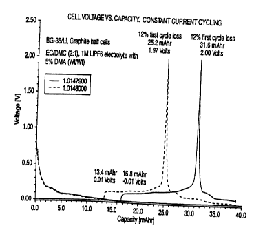
Figure 1 shows the performance of two cells
prepared with a negative electrode (anode) of carbonaceous
material designated as BG-35 cycled against a lithium metal
electrode. The electrolyte is EC/DMC (ethylene carbonate/
dimethyl carbonate) in a ratio by weight of 2:1: one molar
LiPF6 electrolyte: and including 5 percent by weight
~.10 ,~ dimethyl adipate. Figure 1 shows a voltage/capacity plot
for BG-35 graphite carbon electrode cycled with the lithium
metal counterelectrode, using constant current cycling at
~ 0.2 milliamps per square centimeter, between 0.01 and 2.0
volts, using 42 milligrams of the BG-35 active material.
I5 Iiere,'.the electrolyte constitutes a mixture of 95% EC/DMC,
LiPFs and 5% DMA, more specifically: 5% DMA (or 5 gram) +
95% (or 95 gram) of iM EC/DMC, LiPFs electrolyte.
Figure 2 is a voltage/capacity plot similar to
20 that described for Figure 1. The graphite is SFG-15/MCMB
2528 in a 50:50 weight ratio. Figure 2 is a voltage/
capacity plot for the SFG-15/MCNB graphite carbon
electrode cycled with a lithium metal counterelectrode
using constant current cycling at ~ 0.2 milliamps per
25 square centimeter, between 0.01 and 2.0 volts, using 36 mgs
of the graphite active material. The electrolyte is one
molar LiPF6 in a solution of EC/DMC. The weight ratio of
solvent is 2:1 of EC/DMC. In the formulation of Figure 2,
the DMA plasticizes was essentially completely removed by
30 methanol extraction.
Figure 3 shows voltage/capacity plot for an
electrode formulation prepared similar to Figure 2, except
that the plasticizes was essentially completely extracted
35 by vacuum extraction.
9
CA 02322039 2000-08-18
WO 99/44246 PCT/US99/02593
Figure 4 is a two-part graph, with Figure 4A
showing coulombic efficiency versus cycles, and Figure 4B
showing discharge capacity versus cycles. The cells have
BG-35 negative electrode ( anode ) and LMO ( nominally LiMn,O, )
positive electrode (cathode); the electrolyte is
EC/DMC/DMA:64.2% EC/30.8% DMC/5.0% DMA by weight, with 1M
LiPF6 salt.
Figure 5 is a two-part graph, with Figure 5A
- showing coulombic efficiency versus cycles, and Figure 5B
,._ showing discharge capacity versus cycles. The cells have
4
the same BG-35/LMO electrodes and salt as Figure 4, but the
solvent weight ratio is 53.3% EC/26.7% DMC/20.0% DMA.
;. Figure 6 is a two-part graph, with Figure 6A
showing coulombic efficiency versus cycles, and Figure 6B
showing discharge capacity versus cycles. The cells have
the same BG-35/LMO electrodes and salt as Figure 4, but the
solvent weight ratio is 60% EC/30%'DMC/10% DMA.
Figure 7 shows cycling performance of respective
5%, 10% and 20% DMA cells taken from Figures 4, 5 and 6.
Figure 8 is a two-part graph, with Figure SA
showing coulombic efficiency versus cycles, and Figure 8B
showing discharge capacity versus cycles. The cells are
BG-35/LMO, EC/DMC 1M LiPF~, with DMA as separator
plasticizes.
Figure 9 is an illustration of a cross-section of
a thin battery or cell embodying the invention.
IO
= CA 02322039 2000-08-18
WO 99/44246 PCTIUS99/OZ593
The invention provides, for the first time, a key
cell component which is stabilized against decomposition
during cyclic operation of an electrochemical cell. The
components of the cell are formed from a specifically
selected class of new plasticizers which are resistant to
, decomposition by electrochemical breakdown. Such
decomposition and resultant formation of byproducts,
including gaseous byproducts, are problems encountered with
conventional plasticizers used today. Advantageously, the
plasticizes selected for use in the present invention
performs a dual function as both a plasticizes and
electrolyte solvent. Such dual function compound has
heretofore not been suggested. Before further describing
the invention, it is useful to understand problems
associated with present electrode and electrolyte
formulations using conventional plasticizers.
Conventional plasticizers, such as DBP (dibutyl
phthalate) are included in the precursor formulation from
which electrode and separator elements are formed. Other
common plasticizers include dimethylthalate,
diethylthalate, trisbutoxyethyl phosphate, and trimethyl
trimellitate. The DBP (dibutyl phthalate) is particularly
preferred for use in combination with polymeric materials
such as VdF (vinylidene fluoride) and HFP
(hexafluoropropylene), PVC, PAN and the like.
Referring to U.S. Patent Numbers 5,418,091:
5,456,000; 5,460,904; and 5,540,741: it can be seen that
such plasticizers are essentially completely extracted
immediately after formation of the cell component, and
before assembly of the completed cell. It is necessary to
11
CA 02322039 2000-08-18
WO 99/44246 PCf/US99102593
essentially completely remove the plasticizes, DBP and the
like, because they are not electrochemically stable and
will decompose and interfere with cell performance. Each
of the four aforesaid patents is incorporated herein by
reference in its entirety, describing negative electrode,
positive electrode, and electrolyte formulations with
removal of plasticizes before making a cell. The present
invention obviates the need for costly and time-consuming
removal of plasticizes.
t
In view of the difficulties mentioned above, very
elaborate extraction techniques are used to remove the
plasticizes after it has imparted the necessary properties
to the precursor cell components. The plasticizes is
removed either by solvent extraction, where it is
transferred to a liquid solvent phase from which it may be
readily recovered, or by vacuum extraction. Those skilled
in the art will understand that solvent extraction and
vacuum extraction are energy intensive, complex, require
series of steps, good process control , and are very costly .
The present invention defines a new approach to
solving the problem. By the present invention, a new class
of plasticizers are selected which are electrochemically
stable and have properties similar to those desired in an
electrolyte solvent. Such novel plasticizers may remain in
the cell component after fabrication where they function as
part of the solvent mixture. The plasticizers of the
invention are generally characterized as dibasic esters
based on adipates. They have the general formula as shown
in Table I, where "R" represents a low alkyl selected from
methyl, ethyl, butyl, pentyl, and hexyl. Accordingly, "R"
represents a low alkyl, having up to six carbon atoms. The
plasticizers of the invention are further characterized by
electrochemical stability up to about ~.5 volts, and by '
disassociatingly solubilizing the metal salt of the
12
CA 02322039 2000-08-18
W0~99/44Z46 PCT/US99/02593
electrolyte. The plasticizers of the invention have
characteristics consistent with desired electrolyte
solvents, and they may constitute a portion of the solvent
mixture.
The preferred characteristics of exemplary
plasticizers of the invention are given in Table II. It is
preferred that the solvent mixture of the electrolyte
comprise an organic solvent selected from the group
; consisting of ethylene carbonate (EC), dimethyl carbonate
(DMC), diethyl carbonate (DEC), dipropyl carbonate (DPC),
dibutyl carbonate (DBC), diethoxy ethane (DEE), ethyl
methyl carbonate (EMC), butylene carbonate (BC), vinylene
carbonate (VC), propylene carbonate (PC), and mixtures
thereof. Refer to Table III for solvent characteristics.
The plasticizes is miscible with the other solvents and
forms a part of the solvent mixture.
Although the plasticizes of the invention may
remain as a part of the cell component after its
fabrication, it is preferable to remove at least a portion
of it. In any event, the solubilizing plasticizes of the
invention, forming a part of the solvent mixture, is
present in an amount not greater than the amount by weight
of any other one of the organic solvent components. In an
exemplary mixture, the solvent comprised EC/DMC in a weight
proportion of 2:1, and also included the DMA plasticizes of
the invention (dimethyl adipate). The DMA was present in
an amount of 5 percent by weight of the solvent mixture,
and the EC/DMC/LiPF~ ( 1M) constituted 95 percent by weight.
Preferred plasticizers are dimethyl adipate (DMA)
and diethyl adipate (DEA). Dimethyl adipate is available
from the Dupont Chemical Company and is available under the
trade name "DBE-6", dibasic ester (dimethyl adipate), 99
percent purity. A 99 percent purity DMA is available from
13
CA 02322039 2000-08-18
WO 99/4424b PCTNS99/02593
Aldrich Chemical Company, Inc., of Milwaukee, Wisconsin.
Physical characteristics of the dimethyl adipate available
from both Dupont and Aldrich are given in Table II.
According to Aldrich and Dupont, the dimethyl
adipate is synonymous with dimethyl hexanedionate, .
hexanedionic acid, dimethyl ester (9CI) and methyl adipate.
Another commercially available formulation is DBE-4 product
trade name, which represents a mixture of DMA and DEA.
It should be noted that the melting point of DMA
is lower than the conventionally used DBP, therefore
lamination of cell electrode and separator parts would need
to be lowered. Such lamination presently occurs in a range
of about 110 to 115°C, and such lamination preferably
occurs with DMA at around 100°C.
Graphite and lithium metal oxide electrode active
materials were used to prepare electrode formulations along
with the novel plasticizes of the invention, and then
tested in electrochemical cells. Test cells were also
prepared having a polymeric separator formed with the
plasticizes of the invention. Selected results are as
recorded in Figures 1-8. A typical cell configuration will
be described with reference to Figure 9.
The electrochemical cell or battery which uses
the novel plasticizes of the invention will now be
described, with reference to Figure 9. By convention, an
electrochemical cell comprises a first electrode, a
counterelectrode, which reacts electrochemically with the
first electrode, and an electrolyte which is capable of
transferring ions between the electrodes. A battery refers
to one or more electrochemical cells. Referring to Figure
4, an electrochemical cell or battery l0 has a negative
electrode side 12, a positive electrode side 14, and an
i4
~
, CA 02322039 2000-08-18
' WO 99/44246 PCT/US99/02593
electrolyte/separator 16 therebetween. The negative
electrode is the anode during discharge, and the positive
electrode is the cathode during discharge. The negative
electrode side includes current collector 18, typically of
nickel, iron, stainless steel, and copper foil, and
negative electrode active material 20. The positive
electrode side includes current collector 22, typically of
aluminum, nickel, and stainless steel, and such foils may
have a protective conducting coating foil, and a positive
. electrode active material 24. The electrolyte/separator 16
is typically a solid electrolyte, or separator and liquid
electrolyte. Solid electrolytes are typically referred to
as polymeric matrixes which contain an ionic conductive
medium. Liquid electrolytes typically comprise a solvent
and an' alkali metal salt which form an sonically conducting
liquid. In this latter case, the separation between the
anode and cathode is maintained, for example, by a
relatively inert layer of material such as glass fiber.
Essentially, any lithium ion containing conducting
electrolyte may be used, that is stable up to 4.5 volts or
more. Essentially any method may be used to maintain the
positive and negative electrodes spaced apart and
electrically insulated from one another in the cell.
Accordingly, the essential features of the cell are the
positive electrode, a negative electrode electrically
insulated from the positive electrode, and an sonically
conducting medium between the positive and negative
electrodes. Examples of a suitable separator/electrolyte,
solvents, and salts are described in U.S. Patent
No.4,830,939 showing a solid matrix containing an sonically
conducting liquid with an alkali metal salt where the
liquid is an aprotic polar solvent; and U.S. Patent Nos.
4,935,317: 4,990,413; 4,792,504; 5,037,712: 5,418,091:
5,456,000; 5,460,904; 5,463,179; and 5,482,795. Each of
the above patents is incorporated herein by reference in
CA 02322039 2000-08-18 '
' WO 99/44246 PGT/US99/02593
its entirety. Protective bagging material 40 covers the
cell and prevents infiltration of air and moisture.
Electrodes of the invention are made by mixing a
binder, plasticizes, the active material, and carbon powder
(particles of carbon). The binder desirably is a polymer.
The plasticizes is compatible with the polymer. A paste
containing the binder, plasticizes, active material and
carbon is coated onto a current collector. The positive
l0 ; electrode comprises a preferred lithium manganese oxide
active material of the invention. For the positive
electrode,~the content is typically as follows: 60 to 80
percent by weight active material; 2 to 8 carbon black, as
the electric conductive diluent; and 5 to 15 percent
binder, preferably chosen to enhance ionic conductivity;
and 10 to 25 weight percent plasticizes. Stated ranges are
not critical. The amount of active material may vary.
These materials are mixed and blended together with a
casting solvent. Acetone is a suitable solvent. The
mixture is then coated onto a glass plate to achieve the
desired thickness for the final electrode. The negative
electrode of the invention preferably comprises about 55 to
75 percent by weight of graphite active material, and more
preferably, 60 to 70 percent by weight, with the balance
constituted by the binder and preferred plasticizes.
Preferably, the negative electrode is prepared from a
slurry, which is coated onto a glass plate using
conventional casting techniques as described with respect
to the positive electrode.
The electrolyte used to form a completed cell
comprises an organic solvent or solvent mixture with
preferred solvents as shown in Table III. The solvent also
comprises the plasticizes of the invention in an amount up
to about 35 weight percent. The solvent contains typically '
a one molar solution of a lithium metal salt, such as
16
CA 02322039 2000-08-18
' WO 99f44246 PCT/US99102593
LiPF6. The positive and negative electrodes are maintained
in a separated, spaced-apart condition using a fiberglass
layer or separator of an equivalent design. In an
alternative embodiment, the separator between the
electrodes is also formed from a polymer formulation using
the plasticizer of the invention.
The electrochemical cell which utilizes the novel
plasticizer of the invention may be prepared in a variety
~ of ways. In one embodiment, the negative electrode may be
metallic lithium. In more desirable embodiments, the
negative electrode is an intercalation active material,
such as, metal oxides and graphite. When a metal oxide
active material is used, the components of the electrode
are the metal oxide, electrically conductive carbon, and
binder; in proportions similar to that described above for
the positive electrode. In a preferred embodiment, the
negative electrode active material is graphite particles.
For test purposes, test cells were fabricated using lithium
metal electrodes. When forming cells for use as batteries,
it is preferred to use an intercalation metal oxide
positive electrode and a graphitic carbon negative
electrode.
Various methods for fabricating electrochemical
cells and batteries and for forming electrode components
are further described immediately below. The invention is
not, however, limited by any particular fabrication method
as the novelty lies in the unique electrolyte. Accordingly,
additional methods for preparing electrochemical cells and
batteries may be selected and are described in the art, for
example, in U.S. Patent Nos. 5,435,054 (Tonder & Shackle);
5,300,373 (Shackle): 5,262,253 (Golovin): 4,668,595:
4,830,939 (Lee & Shackle); and particularly 5,418,091;
5,456,000; 5,460,904, and 5,540,741 assigned to Bell
17
CA 02322039 2000-08-18 .
WO 99/44246 PCT/US99/02593
Communication Research. Each of the above patents is
incorporated herein by reference in its entirety.
Txample II
A graphite electrode was fabricated by solvent
casting a slurry of BG-35 graphite, binder, plasticizes,
and casting solvent. The graphite, BG-35, was supplied by
Superior Graphite Corporation, Chicago, Illinois. The BG
series is a high purity graphite derived from a flaked
l0 ~ natural graphite purified by heat treatment process. The
physical features are given in Table IV. The binder was a
copolymer of polyvinylidene difluoride (PVDF) and
hexafluoropropylene (HFP) in a molar ratio of PVDF to HFP
of 88:.12. This binder is sold under the designation of
Kynar'Flex 2801~, showing it's a registered trademark.
Kynar Flex is available from Atochem Corporation. The
plasticizes was dimethyl adipate. An electronic grade
casting solvent was used. The slurry was cast onto glass
and a free-standing electrode was formed as the casting
solvent evaporated. The slurry composition for the
negative electrode was as follows:
Component Wet Weight % ~y Weight %
Graphite 23.4 56.0
25. Super P 0.9 2.2
Binder 6.8 16.4
Plasticizes 10.5 25.4
Solvent 5g,4
Total 100.0 100.0
The counter-electrode was lithium metal. A glass
fiber separator was used between the electrodes to prevent
them from electrically shorting. An electrochemical cell
of the first electrode, separator, and counter-electrode
was formed.
18
CA 02322039 2000-08-18
WO 99!44246 PCT/US99102593
The electrolyte used to form the completed final
cell or battery comprised a solution of 95 percent by
weight EC/DMC and 5 percent by weight DMA, which remained
after fonaation of the electrode. = The weight ratio of EC
to DMC was 2:1. The solvent included one molar LiPF6 salt.
The two electrodes were maintained in separated condition
using a fiberglass layer. The electrolyte solution
interpenetrated the void spaces of the fiberglass layer.
The results of constant current cycling are shown in Figure
; 1. Figure 1 shows a voltage/capacity plot of BG-35
graphite cycled with a lithium metal electrode using
constant current cycling at ~ 0.2 milliamps per square
centimeter, between 0.01 and 2.0 volts vs. Li/Li'. In
Figure 1, the results of cycling two similar cells are
i5 shown. One cell is designated L0147900 (1479) and the
other is L0148000 (1480). The data for the 1479 cell is
given below, followed directly by the data for the 1480
cell stated in parentheses. The cycling data was obtained
using 42 (40) milligrams of the BG-35 active material. The
electrolyte is as stated above. The test was conducted
under ambient conditions. In the first half-cycle, lithium
is removed from metallic electrode and intercalated into
the graphite electrode. Once essentially full
intercalation at the graphite electrode was completed,
corresponding to about LilCs, the voltage had dropped to
approximately 0.1 volts, representing about 400 (335)
milliamp hours per gram, corresponding to about 16 . 8 ( 13 . 4 )
milliamp hours, based on the 42 (40) milligrams of active
material. In the second-half cycle, lithium is de-
intercalated from the graphite and returned to the metallic
electrode, until the average voltage is approximately 2
volts vs. Li/Li'. The deintercalation corresponds to
approximately 352 (295) milliamp hours per gram,
representing approximately 14.8 (11.8) milliamp hours,
based on the 42 (40) milligrams of active material. This
completes an initial cycle. The percentage difference
19
CA 02322039 2000-08-18
WO 99/44246 PCTIUS99/82593
between the 16.8 (13.4) milliamp hours per gram capacity
"in" and the 14.8 (11.8) milliamp hours per gram capacity
"out", divided. by the initial 16.8 (13.4) capacity "in"
corresponds to a surprisingly low 12 percent first cycle
loss for each of cells 1479 and 1480.
Example II '
The flexibility of the plasticizes of the
invention can be further understood by reference to the
~ following examples and the results shown in Figures 2 and
3. For comparative purposes, electrodes were prepared
using DMA as plasticizes, as mentioned above, but having
DMA extracted after formation of the electrode. Methanol
was used as the extraction solvent. Graphite electrodes
were prepared as described in Example I and according to
the weight proportions shown therein, except that the
graphite was a combination of SFG-15 and MCMB 2528 in a
50:50 weight ratio. The electrodes comprised 36 milligrams
of active material. The area of the electrodes used in
Figures 2 and 3 are the same as that shown in Figure 1,
namely 2.4 sq. centimeters. The aforesaid 36 milligrams of
graphite active material corresponds to a 56 percent
loading. The electrode slurry casting formulation
comprised, on a weight basis: 25. 4% DMA; 56% Graphite ( 50%
SFG-15/50% MCMB 2528); 16.4% Kynar 2801 (PVDF:HFP); and
2.2% Super F (MMM Carbon) carbon black.
Figure 2 shows a voltage/capacity plot of SFG-15
and MCM8, 2528,X 50:50 graphite cycled with a lithium metal
electrode using constant current cycling at ~ 0.2 milliamps
per square centimeter, between 0.01 and 2 volts vs. Li/Li;.
In Figure 2, the results of cycling two similar cells are
shown. one cell is designated L01475 (1475) and the other
is L01476 (i476). The data for the 1475 cell is given
below, followed directly by the data for the 1476 cell '
stated in parentheses . The cycling data was obtained using
' . CA 02322039 2000-08-18
WU 99/44246 PCT/US99/02593
36 milligrams of the active material. The electrolyte is
one molar LiPFs in a solution of EC/DMC in a 2:1 weight
ratio. In this case, essentially all of the DMA was
extracted by methanol. Therefore, DMA did not form a
detectable part of the solvent solution. As in the case
with respect to Figure 1, in the first-half cycle, lithium
is re~aoved from the metallic electrode and intercalated
into the graphite electrode. When essentially full
intercalation of the graphite electrode is complete,
~ corresponding to LiC6, the voltage has dropped to
approximately 0.01 volts, representing about 383 (386)
mi lliamp hours per gram, corresponding to about 13 . 8 ( 13 . 9 )
milliamp hours, based on 36 (36) milligrams of active
material. In the second half cycle, the lithium is
deintercalated from the graphite and returned to the
metallic electrode until the average voltage is
approximately 2 volts vs. Li/Li'. The deintercalation
corresponds to approximately 341 (344) milliamp hours per
gram, representing approximately 12.3 (12.4) milliamp hours
based on 36 (36) milligrams of active material. This
completes an initial cycle. The percentage difference
between the 13.8 (13.9) milliamp hours per gram capacity
"in" and the 12.3 (12.4) milliamp hours per gram capacity
"out", divided by the initial 13.8 (13.9) capacity "in",
corresponds to a surprisingly low first cycle loss. As
shown in Figure 2, for the two cells (1475 and 1476)
tested: the first exhibited a first cycle loss of 10.9
percent, and the second exhibited a first cycle loss of
10.8 percent.
21
CA 02322039 2000-08-18
WO 99/44246 PCT/US99/02593
Example III.
A graphite electrode was fabricated in the same
manner as described for Example II, except that the DMA
plasticizes was at least partially removed by vacuum.
Figure 3 shows a voltage capacity plot of the SFG-15/MCMB
2528 electrode cycled with a lithium metal electrode, using
constant current cycling at ~ 0.2 milliamps per square
centimeter, between 0. 01 and 2. 0 volts vs . Li/Li;, using 35
milligrams of the graphite active material. The
f electrolyte is one molar LiPFs in a solution of EC/DMC in
a 2:1 weight ratio. In this case, essentially all of the
DMA was extracted by vacuum. Therefore, DMA did not form
a detectable part of the solvent solution. No DMA in the
electrolyte. In the first half cycle, lithium is removed
from the metallic electrode and intercalated into the
graphite electrode as described above. Then, the lithium
is deintercalated from the graphite and returned to the
metallic electrode, as described in the examples above.
The percentage difference between the 12.4 milliamp hours
per gram capacity "in" and the 10.9 milliamp hours per gram
capacity "out", divided by the initial 12.4 capacity "in",
corresponds to a surprisingly low 12 percent first cycle
loss. It can be seen again that DMA may successfully
remain in the cell as a plasticizes without extraction, or
extraction may be done if desired. The capacity of the
cell is not affected by the DMA due to electrochemical
stability of the DMA and its suitability to form a portion
of the solvent mixture.
ale IP
Positive electrodes were also fabricated by
solvent casting of the invention, casting a slurry of
lithium manganese oxide, conductive carbon, binder,
plasticizes and solvent, as in a manner similar to Example
I. A preferred lithium manganese oxide (LMO) cathode was
formed, and the lithium manganese oxide was LiMn,O"
22
CA 02322039 2000-08-18
' WOI99144246 PCTIUS99I02S93
supplied by Kerr-McGee (Soda Springs, Idaho); and the
conductive carbon was Super P, available from MMM carbon.
Kynar Flex co-polymer, described above, was used as the
binder, along with the preferred plasticizer of the
invention. Electronic grade acetone was used as a casting
solvent. The cathode slurry was cast onto aluminum foil
coated with polyacrylic acid/conductive carbon mixture.
The slurry was cast onto glass, and a free-standing
electrode was formed as the solvent evaporated. An
.r exemplary cathode slurry composition is as follows:
Component , Wet We~~,ght % p~,y Weig.ht
LiMn,O, 28 . 9 %
65 . 0
Super P 2.5 5.5
Binder 4.5 10.0
Plasticizer 8.7 19.5
Solvent 55.4
Total 100.0 100.0
Positive electrodes for cells are easily
prepared, as noted above, using the preferred plasticizer.
The plasticizer may be removed, only partially removed, or
remain in the cell in accordance with the examples
described above with respect to the negative electrode.
gi'~e V (5% DMA Solvent)
Graphite (BG-35) and LMO electrodes, prepared as
described above, were tested in a cell having an
electrolyte composition comprising DMA. The electrolyte
used to form the completed final cell, or battery,
comprised of solution of 95% by weight EC/DMC and 5 weight
% DMA. The electrolyte salt was one molar LiPF~. The
weight ratio of EC to DMC was 2:1. The two electrode
layers were arranged with an electrolyte layer in between,
and the layers were laminated together using heat and
pressure as per the Bell Communication Research patents
listed earlier.
23
CA 02322039 2000-08-18 ' '
WO 99/44246 PCT/US99/02593
Figure 4 contains the results of testing of three
cells with cell designated 1261 showing data points with
open squares, cell 1263 data in the form of a straight
line, and cell 1264 showing data designated with filled-in
boxes. Figure 4 is a two-part graph. Figure 4A shows the
good rechargeability of the LMO/BG-35 graphite cells.
Figure 4B shows the good cycling and capacity of the cells .
Charge and discharge are at ~ 2.0 amp hours per centimeter
square, between 3.0 and 4.2 volts for up to about 100
cycles. In Figure 4A, the coulombic efficiency versus
cycle is very good. In Figure 4B, after 100 cycles,
approximately 82-83% capacity is maintained.
dole VI (10% DMA Solvent)
. Cells were prepared as per Example v, except that
the solvent mixture contained a greater proportion by
weight of DMA.
Graphite (BG-35) and LMO electrodes, prepared as
described above, were tested in a cell having an
electrolyte solution of 90% by weight EC/DMC and IO weight
% DMA. The electrolyte salt was one molar LiPF6. The
weight ratio of EC to DMC was 2:1. The two electrode
layers were laminated with the electrolyte layer in between
as described above.
Figure 5 contains the results of testing of four
cells with cell designated 1257 showing data points with
open squares, cell 1259 data in the form of a straight
line, cell 1260 showing data designated with filled-in
boxes, and cell 1258 data shown as filled-in circles.
Figure 5 is a two-part graph. Figure 5A shows the
excellent rechargeability of the LMO/BG-35 graphite cells.
Figure 5B shows the excellent cycling and capacity of the
cells. Charge and discharge are under same conditions as '
Example V. In Figure 5A, the coulombic efficiency versus
24
'. CA 02322039 2000-08-18
' W~99144246 PCT/US99/02593
cycle is very good, and in Figure 58, it can be seen that
after 100 cycles, approximately 81-83% capacity is
maintained.
~ple VII (20% DMA Solvent)
Graphite (BG-35) and LMO electrodes, prepared as
described above, were tested in a cell having an
electrolyte solution of 80% by weight EC/DMC and 20 weight
% DMA. The electrolyte salt was one molar LiPFs. The
~ weight ratio of EC to DMC was 2:1. The two electrode
layers were laminated with the electrolyte layer in between
- as described above.
Figure 6 contains the results of testing of three
cells 'with cell designated 1266 showing data points with
open squares, cell 1268 data in the form of a straight
line, and cell 1269 showing data designated with filled-in
boxes. Figure 6 is a two-part graph. Figure 6A shows the
good rechargeability of the LMO/BG-35 graphite cells.
Figure 6B shows the good cycling and capacity of the cells.
Charge and discharge are under the same conditions as
Example V. In Figure 6A, the coulombic efficiency versus
cycle is very good, and in Figure 6B, it can be seen that
after 100 cycles, approximately 78-80% capacity is
maintained.
To further emphasize the good coulombic
efficiency and discharge capacity versus cycles, exemplary
data from the 5% DMA ( Example V) , 10% DMA ( Example VI ) , and
20% DMA (Example VII) were combined in single graph. This
can be seen in Figure 7.
E~ole VIII
Several cells were prepared, similar to the
aforesaid examples of graphite and LMO electrodes, but also
using a separator formed with the DMA plasticizes of the
CA 02322039 2000-08-18 ' '
V3'O 99/44246 PCTIUS99/02593
invention. The six cells were SFG-15/MCMB 2528, 50:50, 56%
active material. In this case, the DMA was totally removed
after the cell was laminated and before activation with the
electrolyte. Therefore, the electrode and separator
preparation with the removal of the DMA was similar to the
' processes described earlier with respect to Figures 2 and
3, where the DMA plasticizes was totally removed. The
results of testing the six cells are shown in Figure 8.
Cell 2042 is shown by a dashed line with open squares; cell
~ 2043 is shown by a dashed line with dots: cell 2044 data is
designated;by a gray line; data for cell 2045 is shown by
a dashed line with filled-in squares; data for cell 2047 is
shown by a solid line with open squares: and data for cell
2049 is shown by a fixed solid line with large black
(filled-in) squares. The data of Figure 8 clearly
demonstrates that DMA is a stable alternate plasticizes and
provides performance for electrodes and separators
equivalent to that obtained with conventional DBP
plasticizes. Figure 8A shows that coulombic efficiency is
maintained for as many as 400 cycles. Figure 8B shows that
in the case of cell 2044 after 400 cycles, 83% of initial
capacity is maintained, at 2 milliamps per centimeter
square life cycling. The data obtained at one milliamp per
centimeter square life cycling for less than 250 cycles is
also shown for comparative purposes.
Reviewing the data in the various figures, it is
clear that DMA is acceptable for use as a plasticizes for
separator polymeric electrolyte layer, and that it is not
necessary to remove it before the activation step. The
activation step indicates the step at which electrolyte
solvent and salt is added to the cell. Therefore, it is
possible to include DMA as a portion of the electrolyte
solvent salt mixture. It is also acceptable to use DMA as
plasticizes in each laminate layer of the cell, anode,
cathode, and separator, and it is not necessary to remove
26
' CA 02322039 2000-08-18
WO'99/44246 PCT/US99/02593
it, thus permitting it to fona a part of the cell solvent
mixture. Under current processing techniques, the
extraction step currently practiced for removing the
plasticizes is useful for removing~water. Therefore, it is
unlikely that all plasticizes will be permitted to remain
in the cell, since its extraction is coincident with water
removal. However, since the DMA is a stable plasticizes,
one not need be concerned with removing DMA down to a point
of nearly undetectable amounts, as is presently done in the
. case of DBP. DMA was included as part of the electrolyte
formulation to prove its electrochemical stability in
Figures 1,'4, 5, 6, and 7, and this stability was clearly
proven. It is suggested that the greatest amount of DMA
includable in the electrolyte system preferably up to about
20%. As shown in Figures 4 through 7, BG-35/LMO cells with
5-20 weight percent of DMA in the electrolyte all show
reasonable first-cycle loss. These first-cycle losses
ranged from 14-19 percent, and cycling performance was 78-
82 percent, after about 100 cycles. Therefore, it appears
that up to 20% DMA in the electrolyte formulation is
acceptable. In that regard, Figures 2 and 3 show graphite
half-cells, where the DMA plasticizes was totally removed
by methanol ( Figure 2 ) or vacuum extraction ( Figure 3 ) . In
comparing Figures 1, 2, and 3, it can be seen that all
three cells show reasonable first-cycle loss (10.8-12.1%).
Figure 8 demonstrates using DMA as the separator
plasticizes, where DMA was totally removed before the
activation step, showing it to be a stable alternate
plasticizes for processing.
When reviewing the data of all of the Figures 1
through 8, several conclusions are obtained. The first
cycle loss, when using DMA as a plasticizes, is relatively
low. The first cycle loss, when using DMA as a part of the
electrolyte is also relatively low. This demonstrates the
electrochemical stability of DMA. The good capacity
27
CA 02322039 2000-08-18 . ~ -
WO 99/44246 PCTIUS991~02593
retention and cyclability is demonstrated for the various
conditions, both half-cells and full cells, for Figures 1
through 8. Therefore, it is possible to conclude that the
DMA is a very good alternate plasticizer for processing .
(Figures 2, 3, and 8) and it also has the potential for not
being removed before cell activation With the electrolyte.
That is, it shows great potential for saving process time -
and cost by remaining in the cell as part of the
electrolyte solvent in an amount of up to about 20 wt
f percent DMA, based on the formulation shown herein of 20
weight percent DMA; and 80% EC/DMC (2:1 ratio) with one
molar LiPF6~.
Additional physical features of the polymer
binder', plasticizer, active materials, and additives (such
as filters) will now be described.
The plasticizer of the invention is not limited
for use with co-polymers of vinylidene fluoride and
hexafluoropropylene. The polymeric material for use with
the plasticizers of the invention may be selected from a
broader class. More particularly, the polymer may be
selected from polymers and copolymers of vinyl chloride,
acrylonitrile, vinylidene fluoride, vinyl chloride and
vinylidene chloride, vinyl chloride and acrylonitrile,
vinylidene fluoride with hexafluoropropylene, vinylidene
f luoride with hexaf luoropropylene and a member of the group
consisting of vinyl fluoride, tetrafluoroethylene, an
trifiuoroethylene. The preferred polymer composition is a
copolymer of VdF and ,HFP, more preferably, the polymer
composition is 75 to 92% vinylidene fluoride and 8 to 25%
hexafluoropropylene. These copolymers are available
commercially from, for example, Atochem North America as
Kynar FLEX. This polymer composition is preferred for both
the preparation of the electrodes and the separator
membrane.
28
' . CA 02322039 2000-08-18
' WO 99144246 PGTIUS99/02593
Inorganic fillers, such as fumed alumina or
silanized fumed silica, may be used to enhance the physical
strength and melt viscosity of the solid-state components,
namely, the electrodes and separators, and to facilitate
absorption of electrolyte solution in the completed cell.
The active materials for inclusion in the positive
electrode are not limited and may include any of a number
of conventionally used positive electrode active materials
such as LiMnzO" LiCoO" and LiNiO~. Active materials for
, inclusion in the negative electrode include petroleum coke,
microbead vcarbon coke, synthetic graphite, natural
graphite, synthetic graphitized carbon fibers and whiskers,
and metal oxides. Those skilled in the art will understand
that metal chalcogenides may be used as positive and
negative electrode active materials. Completed cells are
fonaed. by laminating the electrodes and separator membranes
described above, under heat and pressure, to form a unitary
battery structure. The battery is activated by including
the electrolyte solution comprising the solvent and metal
salt.
29
CA 02322039 2000-08-18 ~ ' ,
VlrO 99/44246 PCT/US99/02593
T1,BLE I
O O _
~ ~
- ' RO-C- ( CHz ) ,-C-OR . -
~ ,,. - . . , _ . .. , .-_
.. .
_ . - ; _ _ .~
0 - O _- y .. _
~ ~
~~O'C' ( ~_ ).-C-OCH,
DMA (dimethyl adipate, CASE' 627-93-0)
,_..
dibasic ester
,:
30
CA 02322039 2000-08-18
WO, 99/44246 PCT/US99102593
TABLE II
Dibasic Ester
Dimethyl Adipate
DMA
Boiling Point 109C to 110C
Melting Point ~ 8C
~ Vapor Pressure ~ 0.2mm
( 20C)
r
Specific Gravity 1.063
Appearance Colorless
Liquid
_5
Purity, 98-99%
31
CA 02322039 2000-08-18
WO 99144246 PCT/US99/02593
O
~ N p
sr ~ o m ~ , w o
~ V O M
V ,.,I
v
~ ~
U U
0 0 ~
sh sr
W ,. v v v ~ ~
N ..
..._
.
_
~ ~
'r 10 t0 V
OO
o ' '
rl 00
0
O '
~c7
U N c~ p
' '~ ~ N ~
H ~ 1 1 I I 1
e~1 t0
H j .1 OD
H O
W W
a o
E U ~ o d' ~ ~ ao
'~ U o o~ ,.In N
, ' a
~ d d ei x . N
N 1 . ,-IN ~ p
e-1. ~-ie1
f"~ N V
U
_
H U
N
U V~ N .
~ ~
U U U ~
.. ~
N i
fl ~1 ' ~ ~
-
~
Js .1-~ ~ 1tf~.1
~ H ~ ~ .O O
~
1 ~ ",,O tT U
.~ .-1
~ \ O V U U
3 .~
~ V O
H H ~, -rlH ?,
N
ro
O
~ ~ O m U ~
O U
- -ri U
i ~ ~ u ~
~ r l~'~ l m r m(j
1 -Ill
A ~
t P O ~ x W
tf7 o In p
1 N
32
CA 02322039 2000-08-18
' WO'99/44246 PCT/US99/02593
1 d' i 1 e~i
1
'
1 d O 1
1 i
1 0~ ri I
1 o
0 1. v a
rr v
1
w o~°o~.°.i'~° ; '.: ~~'' 1
~ ~-1 1 . . x o 1 0 0 1
~I '~ tp ~ ~I
V
N
b ~ n N 1 e ~ W
-i !~
r,l~-I 1~~ 1p M
: e N 0 V
1 i
, r-1V ~ ,.
.~
.N . V
O '
U
i ~"~ W-1
o n ~'
H
' a
o
Ll e-11 ~ V p N ~
~-1tI1
V rl
..
E V
U
O ',
i~ N ,1.1
..... w. .,i
a a
N ~ ~
a
m ~ O
m ~ t,'~
~ ~ O ~ V 3
G .V
~ V V ~
H H ?~- 1.1 ~,
... N
~..~ ~i ld ,1,~ri
~
O N U ~ U
O
l .N
A ~ ~ A ~
t ~ x W
m o m
33
CA 02322039 2000-08-18 ~ ,
WO 99/44246 PGT/US99102593
TABLB IV
Carbon Material BG-35 SFG-15 MPH-2528
Surf ace Area ( mZ/g ) ( BET ) 7 8 . 8 N/A
Coherence Length Le (nm) >1000 >120 >1000
l0
Density (g/cm')~ 0.195 2.26 2.24
Particle Sizel <36 <16 37
' Median Size d~ (gym) 17 8.1 22.5
Interlayer'Distance c/2 (nm) N/A 0.335 0.336
F
Maximum size for at least 90% by weight of graphite
particles.
In xylene.
34
CA 02322039 2000-08-18
WO 99/44246 PCTlUS99102593
In summary, the invention solves the difficult
processing problems associated with removal of conventional
plasticizers after formation of cell components and before
their assembly into a cell. Plasticizers such as DBP have
always been a problem, since DBP readily decomposes when
subjected to conditions of cyclic operation in an
electrochemical cell. Although DBP and similar compounds
have been popular as plasticizers, their deterioration due
to electrochemical instability is highly problematic. In
contrast, the plasticizer family of the invention, which
comprises adipate derivatives, esters, are highly desirable
and have a wide voltage operating range while avoiding
decomposition in a cell.
While this invention has been described in terms
of certain embodiments thereof, it is not intended that it
be limited to the above description, but rather only to the
extent set forth in the following claims.
The embodiments of the invention in which an
exclusive property or privilege is claimed, are defined in
the following claims.
35